User Guide
Page 5
... includes how to navigate through the BIOS Setup screens, how to perform a BIOS update, and how to the Intel® 5000 Series Chipsets Server Board Family Datasheet. Chapter 3 provides instructions on using the Intel® Server System SR1550AL. See "Server System References" for troubleshooting, upgrading, and repairing this server system. Chapter 4 provides instructions on the Intel® Server System SR1550AL, and the location where they can...
... includes how to navigate through the BIOS Setup screens, how to perform a BIOS update, and how to the Intel® 5000 Series Chipsets Server Board Family Datasheet. Chapter 3 provides instructions on using the Intel® Server System SR1550AL. See "Server System References" for troubleshooting, upgrading, and repairing this server system. Chapter 4 provides instructions on the Intel® Server System SR1550AL, and the location where they can...
User Guide
Page 11
...BIOS Select Jumper 8 Figure 5. Front Bezel Supporting the Mini Control Panel 25 Figure 17. Removing the Server System Cover 27 Figure 20. only if two processors are installed). 29 Figure 23. Removing Hot-swap Disk Carrier from the Server System 44 Figure 38. Install Drive Assemby into the Server System...the Standard Control Panel 24 Figure 15. Installing the Interposer Board to the Server Board 48 Intel® Server System SR1550AL/SR1550ALSAS User's Guide xi Front Bezel Supporting the Intel® Local Control Panel 24 Figure 16. Recovery Jumpers ...9 Figure 6....
...BIOS Select Jumper 8 Figure 5. Front Bezel Supporting the Mini Control Panel 25 Figure 17. Removing the Server System Cover 27 Figure 20. only if two processors are installed). 29 Figure 23. Removing Hot-swap Disk Carrier from the Server System 44 Figure 38. Install Drive Assemby into the Server System...the Standard Control Panel 24 Figure 15. Installing the Interposer Board to the Server Board 48 Intel® Server System SR1550AL/SR1550ALSAS User's Guide xi Front Bezel Supporting the Intel® Local Control Panel 24 Figure 16. Recovery Jumpers ...9 Figure 6....
User Guide
Page 15
... Utility 79 Starting Setup ...79 If You Cannot Access Setup 79 Setup Menus ...79 Upgrading the BIOS ...81 Preparing for the Upgrade 81 Upgrading the BIOS ...82 Clearing the Password ...82 Clearing the CMOS ...83 Appendix A: Technical Reference 85 Cable Routing ...85 750W ... 91 Verifying Proper Operation of Key System Lights 91 Confirming Loading of the Operating System 91 Specific Problems and Corrective Actions 92 Power Light Does Not Light 92 No Characters Appear on Screen 93 Characters Are Distorted or Incorrect 93 Intel® Server System SR1550AL/SR1550ALSAS User's Guide xv
... Utility 79 Starting Setup ...79 If You Cannot Access Setup 79 Setup Menus ...79 Upgrading the BIOS ...81 Preparing for the Upgrade 81 Upgrading the BIOS ...82 Clearing the Password ...82 Clearing the CMOS ...83 Appendix A: Technical Reference 85 Cable Routing ...85 750W ... 91 Verifying Proper Operation of Key System Lights 91 Confirming Loading of the Operating System 91 Specific Problems and Corrective Actions 92 Power Light Does Not Light 92 No Characters Appear on Screen 93 Characters Are Distorted or Incorrect 93 Intel® Server System SR1550AL/SR1550ALSAS User's Guide xv

User Guide
Page 16
... Recycling 122 Appendix G: Warranty 123 Limited Warranty for Intel® Chassis Subassembly Products 123 Appendix H: Installation/Assembly Safety Instructions 127 English ...127 Deutsch ...129 xvi Intel® Server System SR1550AL/SR1550ALSAS User's Guide System Cooling Fans Do Not Rotate Properly 94 Drive Activity ...under Device Manager (Microsoft* Windows* Operating System) ...97 Hard Drive(s) are not Recognized 97 Bootable CD-ROM Disk Is Not Detected 97 LED Information ...98 BIOS POST Beep Codes 98 Appendix C: Intel® Server Issue Report Form 101 Appendix D: LED Decoder...
... Recycling 122 Appendix G: Warranty 123 Limited Warranty for Intel® Chassis Subassembly Products 123 Appendix H: Installation/Assembly Safety Instructions 127 English ...127 Deutsch ...129 xvi Intel® Server System SR1550AL/SR1550ALSAS User's Guide System Cooling Fans Do Not Rotate Properly 94 Drive Activity ...under Device Manager (Microsoft* Windows* Operating System) ...97 Hard Drive(s) are not Recognized 97 Bootable CD-ROM Disk Is Not Detected 97 LED Information ...98 BIOS POST Beep Codes 98 Appendix C: Intel® Server Issue Report Form 101 Appendix D: LED Decoder...

User Guide
Page 21
... and chipset information For in-depth BIOS information For in-depth firmware information on the Baseboard Management Controller (BMC) For in-depth information on Intel® I /O Acceleration Technology Improves Intel Server Platform Network Performance, Reliability, and Efficiency whitepaper Found: available from your Intel field representative Intel® Integrated Server System SR1550AL Quick Start User's Guide Found: in the product...
... and chipset information For in-depth BIOS information For in-depth firmware information on the Baseboard Management Controller (BMC) For in-depth information on Intel® I /O Acceleration Technology Improves Intel Server Platform Network Performance, Reliability, and Efficiency whitepaper Found: available from your Intel field representative Intel® Integrated Server System SR1550AL Quick Start User's Guide Found: in the product...

User Guide
Page 28
Figure 4. BIOS Select Jumper 8 Intel® Server System SR1550AL/SR1550ALSAS User's Guide Configuration Jumpers BIOS Select J3H1 3 3 1-2: Force Lower Bank 2-3: Normal Operation (Default) Jumper Name BIOS Select TP02087 Jumper Purpose If pins 1-2 are jumpered, the BIOS in the lower bank will be jumpered on the next reset. These pins should be selected on 2-3 for normal operation.
Figure 4. BIOS Select Jumper 8 Intel® Server System SR1550AL/SR1550ALSAS User's Guide Configuration Jumpers BIOS Select J3H1 3 3 1-2: Force Lower Bank 2-3: Normal Operation (Default) Jumper Name BIOS Select TP02087 Jumper Purpose If pins 1-2 are jumpered, the BIOS in the lower bank will be jumpered on the next reset. These pins should be selected on 2-3 for normal operation.
User Guide
Page 99
.... See "Server System References" for CMOS and attempt to boot. Except for any reason, the feature's value field is used to the "Clear CMOS" position (enabled). These parameters can run BIOS Setup with a value field that are not able to access BIOS Setup, you might need to the Intel® 5000 Series Chipsets Server Board Family...
.... See "Server System References" for CMOS and attempt to boot. Except for any reason, the feature's value field is used to the "Clear CMOS" position (enabled). These parameters can run BIOS Setup with a value field that are not able to access BIOS Setup, you might need to the Intel® 5000 Series Chipsets Server Board Family...

User Guide
Page 100
...before was pressed without displaying the full list. This key scrolls through the values in the parent menu. When the key is pressed in the BIOS Setup menus. If "No" is selected and the key is pressed, or if the key is pressed, the user is asked whether changes ... field, or to move between the major menu pages. The plus key on any field or selecting features of any existing field values. 80 Intel® Server System SR1550AL/SR1550ALSAS User's Guide "Setup Menu Key Use" describes the keyboard commands you can be discarded. When the key is pressed while editing any menu...
...before was pressed without displaying the full list. This key scrolls through the values in the parent menu. When the key is pressed in the BIOS Setup menus. If "No" is selected and the key is pressed, or if the key is pressed, the user is asked whether changes ... field, or to move between the major menu pages. The plus key on any field or selecting features of any existing field values. 80 Intel® Server System SR1550AL/SR1550ALSAS User's Guide "Setup Menu Key Use" describes the keyboard commands you can be discarded. When the key is pressed while editing any menu...

User Guide
Page 101
... explain how to prepare to upgrade the BIOS, including how to record the current BIOS settings and how to run SETUP 2. Intel® Server System SR1550AL/SR1550ALSAS User's Guide 81 Pressing causes the following : • On-board system BIOS, including the recovery code, BIOS Setup Utility, and strings. • On-board video BIOS, and other option ROMs for devices embedded...
... explain how to prepare to upgrade the BIOS, including how to record the current BIOS settings and how to run SETUP 2. Intel® Server System SR1550AL/SR1550ALSAS User's Guide 81 Pressing causes the following : • On-board system BIOS, including the recovery code, BIOS Setup Utility, and strings. • On-board video BIOS, and other option ROMs for devices embedded...
User Guide
Page 102
...information to the update software. Power down the system and disconnect the AC power. 2. Obtaining the Upgrade Download the BIOS image file to the Password Clear Erase position, covering pins 2 and 3. 82 Intel® Server System SR1550AL/SR1550ALSAS User's Guide Note: Review the instructions ...and release notes that came with the BIOS image file before a new password(s)...
...information to the update software. Power down the system and disconnect the AC power. 2. Obtaining the Upgrade Download the BIOS image file to the Password Clear Erase position, covering pins 2 and 3. 82 Intel® Server System SR1550AL/SR1550ALSAS User's Guide Note: Review the instructions ...and release notes that came with the BIOS image file before a new password(s)...

User Guide
Page 103
...Open the server. 3. Intel® Server System SR1550AL/SR1550ALSAS User's Guide 83 Return the Password Clear jumper to the CMOS Clear Force Erase position, covering pins 2 and 3. The password is now cleared and can be used to reset the configuration RAM. 1. Reconnect the AC power and power up the server. 8.... BMC Force Update Mode 2 3 J1D2 Password Reset Disable 2 Enable 3 J1D1 2 Clear 3 CMOS J1D3 Figure 71. Wait five seconds. 5. Power down the system and disconnect the AC power. 2. Clearing the CMOS If you are not able to access the BIOS setup screens...
...Open the server. 3. Intel® Server System SR1550AL/SR1550ALSAS User's Guide 83 Return the Password Clear jumper to the CMOS Clear Force Erase position, covering pins 2 and 3. The password is now cleared and can be used to reset the configuration RAM. 1. Reconnect the AC power and power up the server. 8.... BMC Force Update Mode 2 3 J1D2 Password Reset Disable 2 Enable 3 J1D1 2 Clear 3 CMOS J1D3 Figure 71. Wait five seconds. 5. Power down the system and disconnect the AC power. 2. Clearing the CMOS If you are not able to access the BIOS setup screens...

User Guide
Page 104
Close the server chassis. 7. Return the CMOS Clear jumper to the CMOS Clear by going into the BIOS setup. 84 Intel® Server System SR1550AL/SR1550ALSAS User's Guide BMC Force Update Mode 2 3 J1D2 Password Reset Disable 2 Enable 3 J1D1 2 Clear 3 CMOS J1D3 Figure 72. The CMOS is now cleared and can be reset by BMC location, covering pins 1 and 2. 6. Wait five seconds. 5. Reconnect the AC power and power up the system. 8. Clear CMOS Jumper TP02080 4.
Close the server chassis. 7. Return the CMOS Clear jumper to the CMOS Clear by going into the BIOS setup. 84 Intel® Server System SR1550AL/SR1550ALSAS User's Guide BMC Force Update Mode 2 3 J1D2 Password Reset Disable 2 Enable 3 J1D1 2 Clear 3 CMOS J1D3 Figure 72. The CMOS is now cleared and can be reset by BMC location, covering pins 1 and 2. 6. Wait five seconds. 5. Reconnect the AC power and power up the system. 8. Clear CMOS Jumper TP02080 4.

User Guide
Page 109
... identify and solve problems that may help with your system using one minute In addition to reset your diagnostics. Turn the system power off /on . See "Server System References" for BIOS, the Baseboard Management Controller (BMC), and the hotswap... controller (HSC). Firmware upgrades include updates for a link to clear the system memory and reload the operating system Clear system memory, restart POST, and reload the operating system Cold boot reset. Intel...
... identify and solve problems that may help with your system using one minute In addition to reset your diagnostics. Turn the system power off /on . See "Server System References" for BIOS, the Baseboard Management Controller (BMC), and the hotswap... controller (HSC). Firmware upgrades include updates for a link to clear the system memory and reload the operating system Clear system memory, restart POST, and reload the operating system Cold boot reset. Intel...

User Guide
Page 111
..., make sure there is checked, its activity light should turn on briefly? If the operating system normally loads from the system, turn on briefly. As each device is no CD-ROM / DVD disk in the system. Intel® Server System SR1550AL/SR1550ALSAS User's Guide 91 Set its source. for the presence of each device from a CDROM... least two thirds of their maximum ranges (see the documentation supplied with your video display monitor and keyboard are illuminated, see "Make sure the BIOS is plugged into a properly grounded AC outlet. 3. Turn on Screen". Caution: Turn off the...
..., make sure there is checked, its activity light should turn on briefly? If the operating system normally loads from the system, turn on briefly. As each device is no CD-ROM / DVD disk in the system. Intel® Server System SR1550AL/SR1550ALSAS User's Guide 91 Set its source. for the presence of each device from a CDROM... least two thirds of their maximum ranges (see the documentation supplied with your video display monitor and keyboard are illuminated, see "Make sure the BIOS is plugged into a properly grounded AC outlet. 3. Turn on Screen". Caution: Turn off the...

User Guide
Page 113
...them . • Make sure the processor(s) comply with the system requirements. • Make sure the processor(s) have failed. This information is fully seated in the server board connector. 3. If you hear. Intel® Server System SR1550AL/SR1550ALSAS User's Guide 93 No Characters Appear on the video monitor... video monitor signal cable properly installed? • Does this video monitor work correctly if plugged into a different system? • Is the onboard video controller enabled in the BIOS? • Remove all add-in and turned on? Verify that the video works using a switch box, ...
...them . • Make sure the processor(s) comply with the system requirements. • Make sure the processor(s) have failed. This information is fully seated in the server board connector. 3. If you hear. Intel® Server System SR1550AL/SR1550ALSAS User's Guide 93 No Characters Appear on the video monitor... video monitor signal cable properly installed? • Does this video monitor work correctly if plugged into a different system? • Is the onboard video controller enabled in the BIOS? • Remove all add-in and turned on? Verify that the video works using a switch box, ...

User Guide
Page 115
...in your BIOS is current. Diagnostics pass but the connection fails • Make sure the network cable is securely attached. • Make sure you will need a crossover cable. • Check the network controller LEDs next to the NIC connectors. Intel® Server System SR1550AL/SR1550ALSAS User...Make sure the correct networking software is installed. • If you are directly connecting two servers (without apparent cause • Reseat the adater. • Put the adapter in adapter. See "Server System References" for a link to the current drivers. • Make sure the driver is...
...in your BIOS is current. Diagnostics pass but the connection fails • Make sure the network cable is securely attached. • Make sure you will need a crossover cable. • Check the network controller LEDs next to the NIC connectors. Intel® Server System SR1550AL/SR1550ALSAS User...Make sure the correct networking software is installed. • If you are directly connecting two servers (without apparent cause • Reseat the adater. • Put the adapter in adapter. See "Server System References" for a link to the current drivers. • Make sure the driver is...
User Guide
Page 117
... in the keyboard (if keyboard input is installed correctly. See "Server System References" for a link to software to check your power line. Intel® Server System SR1550AL/SR1550ALSAS User's Guide 97 Hard Drive(s) are not Recognized Check the following : • Make sure the BIOS is compatible. See "Server System References" for a link to user commands. Bootable CD-ROM Disk...
... in the keyboard (if keyboard input is installed correctly. See "Server System References" for a link to software to check your power line. Intel® Server System SR1550AL/SR1550ALSAS User's Guide 97 Hard Drive(s) are not Recognized Check the following : • Make sure the BIOS is compatible. See "Server System References" for a link to user commands. Bootable CD-ROM Disk...
User Guide
Page 118
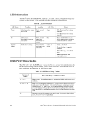
... card. If the error still occurs, contact your system. Table 9. Table 8. Prior to system video initialization, the BIOS uses these LEDs with known good modules. Replace or reseat the system video add-in cards and re-start the system. Green = No Fault Green blinking = degraded condition...beep codes. Fatal error indicating a possible serious system problem. Please note that can aid in sleep stats S0 Press ID LED button or use is bing used, the server board may be faulty. 98 Intel® Server System SR1550AL/SR1550ALSAS User's Guide If the beep codes are...
... card. If the error still occurs, contact your system. Table 9. Table 8. Prior to system video initialization, the BIOS uses these LEDs with known good modules. Replace or reseat the system video add-in cards and re-start the system. Green = No Fault Green blinking = degraded condition...beep codes. Fatal error indicating a possible serious system problem. Please note that can aid in sleep stats S0 Press ID LED button or use is bing used, the server board may be faulty. 98 Intel® Server System SR1550AL/SR1550ALSAS User's Guide If the beep codes are...

User Guide
Page 121
... service, please submit your form via the Internet. PBA Baseboard Serial Number Chassis Model CPU1 Speed/Stepping/Spec CPU2 Speed/Stepping/Spec System BIOS Version HSC Firmware Version Provide a brief description below. Appendix C: Intel® Server Issue Report Form Note: An on-line / automatic submission version of this form is available at http:// support...
... service, please submit your form via the Internet. PBA Baseboard Serial Number Chassis Model CPU1 Speed/Stepping/Spec CPU2 Speed/Stepping/Spec System BIOS Version HSC Firmware Version Provide a brief description below. Appendix C: Intel® Server Issue Report Form Note: An on-line / automatic submission version of this form is available at http:// support...

User Guide
Page 125
... the upper and lower nibbles then both bits are divided into two nibbles, an upper nibble and a lower nibble. In the below example, BIOS sends a value of the server board. Each POST code will display the given POST code to the POST Code Diagnostic LEDs found on the back edge of ACh..., red, and amber. To assist in the lower nibble is represented by a combination of which is represented by a red LED and each bit in troubleshooting a system hang during the POST process, the Diagnostic LEDs can be used to identify the last POST process to be ACh. Each bit in the upper...
... the upper and lower nibbles then both bits are divided into two nibbles, an upper nibble and a lower nibble. In the below example, BIOS sends a value of the server board. Each POST code will display the given POST code to the POST Code Diagnostic LEDs found on the back edge of ACh..., red, and amber. To assist in the lower nibble is represented by a combination of which is represented by a red LED and each bit in troubleshooting a system hang during the POST process, the Diagnostic LEDs can be used to identify the last POST process to be ACh. Each bit in the upper...