
User Guide
Page 1
Intel® Server System SR1550AL/ SR1550ALSAS User's Guide A Guide for Technically Qualified Assemblers of Intel® Identified Subassemblies/ Products Intel Order Number D31972-002
Intel® Server System SR1550AL/ SR1550ALSAS User's Guide A Guide for Technically Qualified Assemblers of Intel® Identified Subassemblies/ Products Intel Order Number D31972-002

User Guide
Page 2
... descriptions at any patent, copyright or other application in which the failure of any time, without notice. Intel may occur. All Rights Reserved ii Intel® Server System SR1550AL/SR1550ALSAS User's Guide Disclaimer Information in this document. Intel, Intel Pentium, and Intel Xeon are trademarks or registered trademarks of their specific application and environmental conditions. No license, express or...
... descriptions at any patent, copyright or other application in which the failure of any time, without notice. Intel may occur. All Rights Reserved ii Intel® Server System SR1550AL/SR1550ALSAS User's Guide Disclaimer Information in this document. Intel, Intel Pentium, and Intel Xeon are trademarks or registered trademarks of their specific application and environmental conditions. No license, express or...

User Guide
Page 6
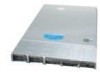
...; USB cable • Peripheral bay filler panel, installed in the server system • Mini control panel, installed in the server system • Active or passive mid-plane, installed in the server system vi Intel® Server System SR1550AL/SR1550ALSAS User's Guide For further information, see the Intel® Server Board S5000PAL User's Guide. Intel® Server System SR1550AL Contents Your Intel® Server System SR1550AL ships with the Intel® Server Board S5000PAL.
...; USB cable • Peripheral bay filler panel, installed in the server system • Mini control panel, installed in the server system • Active or passive mid-plane, installed in the server system vi Intel® Server System SR1550AL/SR1550ALSAS User's Guide For further information, see the Intel® Server Board S5000PAL User's Guide. Intel® Server System SR1550AL Contents Your Intel® Server System SR1550AL ships with the Intel® Server Board S5000PAL.

User Guide
Page 8
http://support.intel.com/support/motherboards/server/sb/CS-010770.htm 上的 Intel Server Boards and Server Chassis Safety Information(《Intel viii Intel® Server System SR1550AL/SR1550ALSAS User's Guide
http://support.intel.com/support/motherboards/server/sb/CS-010770.htm 上的 Intel Server Boards and Server Chassis Safety Information(《Intel viii Intel® Server System SR1550AL/SR1550ALSAS User's Guide

User Guide
Page 9
... power, telephone, and communication cables. They can be present on /off: The power button DOES NOT turn off the server and disconnect the power cord, telecommunications systems, networks, and modems attached to the server before you must adhere to the assembly instructions in which the product is not available, provide some ESD protection... the jumper with a pair of the product and will void the UL listing and other resource as a reference, pay close attention to the safety instructions. Intel® Server System SR1550AL/SR1550ALSAS User's Guide ix
... power, telephone, and communication cables. They can be present on /off: The power button DOES NOT turn off the server and disconnect the power cord, telecommunications systems, networks, and modems attached to the server before you must adhere to the assembly instructions in which the product is not available, provide some ESD protection... the jumper with a pair of the product and will void the UL listing and other resource as a reference, pay close attention to the safety instructions. Intel® Server System SR1550AL/SR1550ALSAS User's Guide ix
User Guide
Page 11
.... Removing an Add-In Card 47 Figure 41. Removing PCI Riser Assembly from the Server System 44 Figure 38. Installing the Server System Cover 27 Figure 21. Removing the Processor 2 Air Dam (Optional - Installing the Interposer Board to the Server Board 48 Intel® Server System SR1550AL/SR1550ALSAS User's Guide xi ChassisComponents 6 Figure 3. Removing the PCIe* Riser Card from the...
.... Removing an Add-In Card 47 Figure 41. Removing PCI Riser Assembly from the Server System 44 Figure 38. Installing the Server System Cover 27 Figure 21. Removing the Processor 2 Air Dam (Optional - Installing the Interposer Board to the Server Board 48 Intel® Server System SR1550AL/SR1550ALSAS User's Guide xi ChassisComponents 6 Figure 3. Removing the PCIe* Riser Card from the...
User Guide
Page 12
... 73 Figure 67. Diagnostic LED Placement Diagram 106 xii Intel® Server System SR1550AL/SR1550ALSAS User's Guide Figure 42. Installing Mini Control Panel into the Server System 54 Figure 47. Removing the Server Board 61 Figure 53. Installing the Intel® RMM and the Intel® RMM NIC Module to the Server System 50 Figure 44. Clear Password Jumper 83 Figure 72...
... 73 Figure 67. Diagnostic LED Placement Diagram 106 xii Intel® Server System SR1550AL/SR1550ALSAS User's Guide Figure 42. Installing Mini Control Panel into the Server System 54 Figure 47. Removing the Server Board 61 Figure 53. Installing the Intel® RMM and the Intel® RMM NIC Module to the Server System 50 Figure 44. Clear Password Jumper 83 Figure 72...
User Guide
Page 13
...About this Manual ...v Manual Organization ...v Product Contents ...vi Intel® Server System SR1550AL Contents vi Safety Information ...vii Important Safety Instructions vii Wichtige Sicherheitshinweise vii Consignes de sécurité ...vii Instrucciones de seguridad importantes vii Chapter 1: Server System References 1 Chapter 2: Server System Features 3 Chassis Component Identification 6 Internal Components ...6 Configuration...Servicing 24 Removing and Installing the Front Bezel 24 Removing the Front Bezel 25 Intel® Server System SR1550AL/SR1550ALSAS User's Guide xiii
...About this Manual ...v Manual Organization ...v Product Contents ...vi Intel® Server System SR1550AL Contents vi Safety Information ...vii Important Safety Instructions vii Wichtige Sicherheitshinweise vii Consignes de sécurité ...vii Instrucciones de seguridad importantes vii Chapter 1: Server System References 1 Chapter 2: Server System Features 3 Chassis Component Identification 6 Internal Components ...6 Configuration...Servicing 24 Removing and Installing the Front Bezel 24 Removing the Front Bezel 25 Intel® Server System SR1550AL/SR1550ALSAS User's Guide xiii
User Guide
Page 14
Installing the Front Bezel 26 Removing and Installing the Chassis Cover 26 Removing the Chassis Cover 26 Installing the Server System Cover 27 Removing and Installing the Processor Air Duct 28 Removing the Processor Air Duct 28 Installing the Processor Air ... the Intel® Integrated RAID Activation Key and the RAID Mini DIMM 55 Removing the Intel® Integrated RAID Activation Key and the RAID Mini DIMM ......... 56 Installing and Removing the RAID Battery Backup Unit (BBU 57 Installing the RAID Battery Backup Unit 57 xiv Intel® Server System SR1550AL/SR1550ALSAS User's...
Installing the Front Bezel 26 Removing and Installing the Chassis Cover 26 Removing the Chassis Cover 26 Installing the Server System Cover 27 Removing and Installing the Processor Air Duct 28 Removing the Processor Air Duct 28 Installing the Processor Air ... the Intel® Integrated RAID Activation Key and the RAID Mini DIMM 55 Removing the Intel® Integrated RAID Activation Key and the RAID Mini DIMM ......... 56 Installing and Removing the RAID Battery Backup Unit (BBU 57 Installing the RAID Battery Backup Unit 57 xiv Intel® Server System SR1550AL/SR1550ALSAS User's...
User Guide
Page 15
...and Removing the Rack Handles 76 Installing the Rack Handles 76 Removing the Rack Handles 76 Chapter 4: Server Utilities 79 Using the BIOS Setup Utility 79 Starting Setup ...79 If You Cannot Access Setup 79 ...System Installation 90 First Steps Checklist ...90 Hardware Diagnostic Testing 91 Verifying Proper Operation of Key System Lights 91 Confirming Loading of the Operating System 91 Specific Problems and Corrective Actions 92 Power Light Does Not Light 92 No Characters Appear on Screen 93 Characters Are Distorted or Incorrect 93 Intel® Server System SR1550AL/SR1550ALSAS...
...and Removing the Rack Handles 76 Installing the Rack Handles 76 Removing the Rack Handles 76 Chapter 4: Server Utilities 79 Using the BIOS Setup Utility 79 Starting Setup ...79 If You Cannot Access Setup 79 ...System Installation 90 First Steps Checklist ...90 Hardware Diagnostic Testing 91 Verifying Proper Operation of Key System Lights 91 Confirming Loading of the Operating System 91 Specific Problems and Corrective Actions 92 Power Light Does Not Light 92 No Characters Appear on Screen 93 Characters Are Distorted or Incorrect 93 Intel® Server System SR1550AL/SR1550ALSAS...

User Guide
Page 16
...not Recognized under Device Manager (Microsoft* Windows* Operating System) ...97 Hard Drive(s) are not Recognized 97 Bootable CD-ROM Disk Is Not Detected 97 LED Information ...98 BIOS POST Beep Codes 98 Appendix C: Intel® Server Issue Report Form 101 Appendix D: LED Decoder 105 ... (RoHS) Compliance 122 End-of-Life / Product Recycling 122 Appendix G: Warranty 123 Limited Warranty for Intel® Chassis Subassembly Products 123 Appendix H: Installation/Assembly Safety Instructions 127 English ...127 Deutsch ...129 xvi Intel® Server System SR1550AL/SR1550ALSAS User's Guide
...not Recognized under Device Manager (Microsoft* Windows* Operating System) ...97 Hard Drive(s) are not Recognized 97 Bootable CD-ROM Disk Is Not Detected 97 LED Information ...98 BIOS POST Beep Codes 98 Appendix C: Intel® Server Issue Report Form 101 Appendix D: LED Decoder 105 ... (RoHS) Compliance 122 End-of-Life / Product Recycling 122 Appendix G: Warranty 123 Limited Warranty for Intel® Chassis Subassembly Products 123 Appendix H: Installation/Assembly Safety Instructions 127 English ...127 Deutsch ...129 xvi Intel® Server System SR1550AL/SR1550ALSAS User's Guide

User Guide
Page 19
... Specifications 88 Table 7. Error Beep Codes Generated by Intel® Remote Management Module 99 Table 11. List of Tables Table 1. Intel® Server System SR1550AL Feature Summary 4 Table 3. Power Supply Output Capability 87 Table 6. Product Regulatory Compliance Markings 117 Intel® Server System SR1550AL/SR1550ALSAS User's Guide xix Setup Menu Key Use 80 Table 5. LED Information ...98 Table 9. POST Progress...
... Specifications 88 Table 7. Error Beep Codes Generated by Intel® Remote Management Module 99 Table 11. List of Tables Table 1. Intel® Server System SR1550AL Feature Summary 4 Table 3. Power Supply Output Capability 87 Table 6. Product Regulatory Compliance Markings 117 Intel® Server System SR1550AL/SR1550ALSAS User's Guide xix Setup Menu Key Use 80 Table 5. LED Information ...98 Table 9. POST Progress...

User Guide
Page 22
.../server/S5000PAL/ To make sure your system falls within the allowed power budget For software to manage your Intel® server Power Budget Tool Found: http://support.intel.com/support/motherboards/server/S5000PAL/ Intel® System Management Software Found: http://support.intel.com/support/motherboards/server/S5000PAL/ For diagnostics test software Diagnostics Found: http://support.intel.com/support/motherboards/server/S5000PAL/ 2 Intel® Server System SR1550AL/SR1550ALSAS...
.../server/S5000PAL/ To make sure your system falls within the allowed power budget For software to manage your Intel® server Power Budget Tool Found: http://support.intel.com/support/motherboards/server/S5000PAL/ Intel® System Management Software Found: http://support.intel.com/support/motherboards/server/S5000PAL/ For diagnostics test software Diagnostics Found: http://support.intel.com/support/motherboards/server/S5000PAL/ 2 Intel® Server System SR1550AL/SR1550ALSAS...
User Guide
Page 24
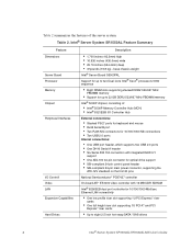
... 2.5 inch hot-swap SATA / SAS drives 4 Intel® Server System SR1550AL/SR1550ALSAS User's Guide Intel® Server System SR1550AL Feature Summary Feature Dimensions Server Board Processor Memory Chipset Peripheral Interfaces I /O Controller ...Hub External connections: • Stacked PS/2* ports for keyboard and mouse • RJ45 Serial B port • Two RJ45 NIC connectors for 10/100/1000 Mb...
... 2.5 inch hot-swap SATA / SAS drives 4 Intel® Server System SR1550AL/SR1550ALSAS User's Guide Intel® Server System SR1550AL Feature Summary Feature Dimensions Server Board Processor Memory Chipset Peripheral Interfaces I /O Controller ...Hub External connections: • Stacked PS/2* ports for keyboard and mouse • RJ45 Serial B port • Two RJ45 NIC connectors for 10/100/1000 Mb...

User Guide
Page 25
... Up to two 650W power supply modules • Six 4-pin fan headers supporting two processor fans, and four system fans • Dedicated non-redundant power supply fan (one per module) • One front panel USB port • One internal USB header providing two USB ports Intel® System Management Software Intel® Server System SR1550AL/SR1550ALSAS User's Guide 5
... Up to two 650W power supply modules • Six 4-pin fan headers supporting two processor fans, and four system fans • Dedicated non-redundant power supply fan (one per module) • One front panel USB port • One internal USB header providing two USB ports Intel® System Management Software Intel® Server System SR1550AL/SR1550ALSAS User's Guide 5
User Guide
Page 26
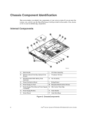
... identify the components of the chassis cover to assist in identifying components. PCI Riser Assembly B. Mini Control Panel Bay if Installed) G. Server Board P. ChassisComponents 6 Intel® Server System SR1550AL/SR1550ALSAS User's Guide Power Supply Air Duct M. Power Supply Module O. Chassis Component Identification This section helps you can also use the Quick Reference Label provided on ...
... identify the components of the chassis cover to assist in identifying components. PCI Riser Assembly B. Mini Control Panel Bay if Installed) G. Server Board P. ChassisComponents 6 Intel® Server System SR1550AL/SR1550ALSAS User's Guide Power Supply Air Duct M. Power Supply Module O. Chassis Component Identification This section helps you can also use the Quick Reference Label provided on ...

User Guide
Page 28
Configuration Jumpers BIOS Select J3H1 3 3 1-2: Force Lower Bank 2-3: Normal Operation (Default) Jumper Name BIOS Select TP02087 Jumper Purpose If pins 1-2 are jumpered, the BIOS in the lower bank will be jumpered on the next reset. These pins should be selected on 2-3 for normal operation. Figure 4. BIOS Select Jumper 8 Intel® Server System SR1550AL/SR1550ALSAS User's Guide
Configuration Jumpers BIOS Select J3H1 3 3 1-2: Force Lower Bank 2-3: Normal Operation (Default) Jumper Name BIOS Select TP02087 Jumper Purpose If pins 1-2 are jumpered, the BIOS in the lower bank will be jumpered on the next reset. These pins should be selected on 2-3 for normal operation. Figure 4. BIOS Select Jumper 8 Intel® Server System SR1550AL/SR1550ALSAS User's Guide

User Guide
Page 29
... Disable 2 Enable 3 J1D1 2 Clear 3 CMOS J1D3 TP02080 Jumper Name Jumper Purpose CMOS Clear If pins 2-3 are jumpered, BMC Force Update Mode is enabled. Recovery Jumpers Intel® Server System SR1550AL/SR1550ALSAS User's Guide 9
... Disable 2 Enable 3 J1D1 2 Clear 3 CMOS J1D3 TP02080 Jumper Name Jumper Purpose CMOS Clear If pins 2-3 are jumpered, BMC Force Update Mode is enabled. Recovery Jumpers Intel® Server System SR1550AL/SR1550ALSAS User's Guide 9

User Guide
Page 30
... Figure 6. DIMM D1 Fault K. DIMM D2 Fault L L. ID LED C. Light Guided Diagnostic LEDs AF000644 10 Intel® Server System SR1550AL/SR1550ALSAS User's Guide Status LED D. DIMM A1 Fault E. DIMM B2 Fault H. DIMM C1 Fault I J K A. Intel® Light Guided Diagnostics The server board contains diagnostic LEDs to help you identify failed and failing components, and to help you...
... Figure 6. DIMM D1 Fault K. DIMM D2 Fault L L. ID LED C. Light Guided Diagnostic LEDs AF000644 10 Intel® Server System SR1550AL/SR1550ALSAS User's Guide Status LED D. DIMM A1 Fault E. DIMM B2 Fault H. DIMM C1 Fault I J K A. Intel® Light Guided Diagnostics The server board contains diagnostic LEDs to help you identify failed and failing components, and to help you...

User Guide
Page 31
I/O Expansion Module (Optional) I. RJ45 Serial B Connector B. Keyboard Figure 7. Power Supply Module 2 (Filler Panel Shown) G. USB Port 5 J. Mouse C. USB Port 6 K. Power Supply Module 1 F. NIC 2 (10/100/1000 Mb) M. Video L. Back Panel Connectors Intel® Server System SR1550AL/SR1550ALSAS User's Guide 11 Back Panel Connectors A B C D NML K J IH GF E TP02216 A. NIC 1 (10/100/1000 Mb) N. Low Profile PCI Express* Add-in Card Slot E. Full Height PCI Add-in Card Slot D. Intel® Remote Management Module NIC (Optional) H.
I/O Expansion Module (Optional) I. RJ45 Serial B Connector B. Keyboard Figure 7. Power Supply Module 2 (Filler Panel Shown) G. USB Port 5 J. Mouse C. USB Port 6 K. Power Supply Module 1 F. NIC 2 (10/100/1000 Mb) M. Video L. Back Panel Connectors Intel® Server System SR1550AL/SR1550ALSAS User's Guide 11 Back Panel Connectors A B C D NML K J IH GF E TP02216 A. NIC 1 (10/100/1000 Mb) N. Low Profile PCI Express* Add-in Card Slot E. Full Height PCI Add-in Card Slot D. Intel® Remote Management Module NIC (Optional) H.