User Guide
Page 7
... settings and screens is written for system technicians who are shipped with the Intel® Server Board S5000VCL. See "Server System References" on using the Intel® Server System SR1530CL / SR1530HCL / SR1530HCLS and/or the Intel® Server System SR1530CLR / SR1530HCLR / SR1530HCLSR. This manual is available in the Intel® Server Board S5000VCL Technical Product Specification. Product Contents The Intel® Server System SR1530CL / SR1530HCL / SR1530HCLS ships with the...
... settings and screens is written for system technicians who are shipped with the Intel® Server Board S5000VCL. See "Server System References" on using the Intel® Server System SR1530CL / SR1530HCL / SR1530HCLS and/or the Intel® Server System SR1530CLR / SR1530HCLR / SR1530HCLSR. This manual is available in the Intel® Server Board S5000VCL Technical Product Specification. Product Contents The Intel® Server System SR1530CL / SR1530HCL / SR1530HCLS ships with the...
User Guide
Page 8
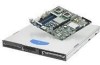
... disk drives to the hard disk drive brackets - Intel® Server System Contents Your Intel® Server System SR1530CL / SR1530HCL / SR1530HCLS and/or the Intel® Server System SR1530CLR / SR1530HCLR / SR1530HCLSR ships with the following items: • One Intel® Server Board S5000VCL/S5000VCLR, installed in the server system • One 400-watt power supply module, installed in the server system • One low-profile riser, installed in a separate...
... disk drives to the hard disk drive brackets - Intel® Server System Contents Your Intel® Server System SR1530CL / SR1530HCL / SR1530HCLS and/or the Intel® Server System SR1530CLR / SR1530HCLR / SR1530HCLSR ships with the following items: • One Intel® Server Board S5000VCL/S5000VCLR, installed in the server system • One 400-watt power supply module, installed in the server system • One low-profile riser, installed in a separate...

User Guide
Page 13
... the Server Board 69 Installing the Server Board 69 Removing the Server Board 71 Replacing the CMOS Battery 72 Replacing the Power Supply (SR1530CL/SR1530CLR 73 Replacing the Power Supply (SR1530HCL/SR1530HCLS and SR1530HCLR/ SR1530HCLSR) ...78 Replacing the Front Panel Board (SR1530CL/SR1530CLR 83 Replacing the Front Panel Board (SR1530HCL/SR1530HCLR 85 Replacing a System Blower 88 Replacing the System Blowers (SR1530CL/SR1530CLR 88 Replacing a System Blower...
... the Server Board 69 Installing the Server Board 69 Removing the Server Board 71 Replacing the CMOS Battery 72 Replacing the Power Supply (SR1530CL/SR1530CLR 73 Replacing the Power Supply (SR1530HCL/SR1530HCLS and SR1530HCLR/ SR1530HCLSR) ...78 Replacing the Front Panel Board (SR1530CL/SR1530CLR 83 Replacing the Front Panel Board (SR1530HCL/SR1530HCLR 85 Replacing a System Blower 88 Replacing the System Blowers (SR1530CL/SR1530CLR 88 Replacing a System Blower...
User Guide
Page 17
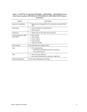
... 13. Intel® Server System SR1530CL / SR1530HCL / SR1530HCLS and Intel Server System SR1530CLR / SR1530HCLR / SR1530HCLSR Feature Summary 2 Table 2. System Status LED Color and Blink Codes 115 Table 9. Error Beep Codes Generated by Intel® Remote Management Module 116 Table 11. NIC LED Descriptions 6 Table 3. System Environmental Specifications 103 Table 6. LED Information ...114 Table 8. Product Regulatory Compliance Markings 158 Table 12. Power Supply Output...
... 13. Intel® Server System SR1530CL / SR1530HCL / SR1530HCLS and Intel Server System SR1530CLR / SR1530HCLR / SR1530HCLSR Feature Summary 2 Table 2. System Status LED Color and Blink Codes 115 Table 9. Error Beep Codes Generated by Intel® Remote Management Module 116 Table 11. NIC LED Descriptions 6 Table 3. System Environmental Specifications 103 Table 6. LED Information ...114 Table 8. Product Regulatory Compliance Markings 158 Table 12. Power Supply Output...
User Guide
Page 21
... Figure 99. Disconnecting Power Cables (SR1530CL/SR1530CLR 74 Figure 74. Installing Power Supply into the Server System (SR1530CL/SR1530CLR 76 Figure 76. Removing the Rack Handle 96 Figure 97. Connecting Power Cables (SR1530CL/SR1530CLR 77 Figure 77. Removing System Blower from Server System (SR1530HCL/SR1530HCLS and SR1530HCLR/SR1530HCLSR 80 Figure 79. Removing Power Supply from Server System (SR1530CL/ SR1530CLR)...89 Figure 89. Removing Blower Bracket with System Blowers from the Server System (SR1530CL/SR1530CLR)....... 75 Figure...
... Figure 99. Disconnecting Power Cables (SR1530CL/SR1530CLR 74 Figure 74. Installing Power Supply into the Server System (SR1530CL/SR1530CLR 76 Figure 76. Removing the Rack Handle 96 Figure 97. Connecting Power Cables (SR1530CL/SR1530CLR 77 Figure 77. Removing System Blower from Server System (SR1530HCL/SR1530HCLS and SR1530HCLR/SR1530HCLSR 80 Figure 79. Removing Power Supply from Server System (SR1530CL/ SR1530CLR)...89 Figure 89. Removing Blower Bracket with System Blowers from the Server System (SR1530CL/SR1530CLR)....... 75 Figure...
User Guide
Page 25
... drive (optional) • NIC1 Activity • NIC2 Activity • Power / Sleep • System Status • Hard Drive Activity One 400-watt power supply module • Non-redundant fans: - (SR1530CL/SR1530CLR) One PCI cooling fan - Two system blowers • One front panel USB port • One internal USB header providing two USB ports Intel® System Management Software Server System User Guide 3
... drive (optional) • NIC1 Activity • NIC2 Activity • Power / Sleep • System Status • Hard Drive Activity One 400-watt power supply module • Non-redundant fans: - (SR1530CL/SR1530CLR) One PCI cooling fan - Two system blowers • One front panel USB port • One internal USB header providing two USB ports Intel® System Management Software Server System User Guide 3

User Guide
Page 32
PCI Add-in Card Bracket E. Hard Drive Brackets (two) J. Chassis Components (SR1530CL/SR1530CLR) 10 Server System User Guide Power Supply G. System Blowers (two) I A E F G H AF001185 A. Slimline Optical Drive Bay Figure 8. Rack Handles (two) B. Processor Air Duct D. System Memory DIMM Sockets F. Control Panel K. Internal Components D C B A K J I . PCI Cooling Fan C. Processor Sockets (two) H.
PCI Add-in Card Bracket E. Hard Drive Brackets (two) J. Chassis Components (SR1530CL/SR1530CLR) 10 Server System User Guide Power Supply G. System Blowers (two) I A E F G H AF001185 A. Slimline Optical Drive Bay Figure 8. Rack Handles (two) B. Processor Air Duct D. System Memory DIMM Sockets F. Control Panel K. Internal Components D C B A K J I . PCI Cooling Fan C. Processor Sockets (two) H.

User Guide
Page 47
... components in this chaper show the Intel® Server System SR1530CL / SR1530CLR with your server product, pay close attention to the "Safety Information" on page iii. Note: Some components in the Intel® Server System SR1530HCL / SR1530HCLS and Intel® Server System SR1530HCLR / SR1530HCLSR are hot-swappable and, where applicable, will be positioned for normal operation. Server System User Guide 25 The instructions for...
... components in this chaper show the Intel® Server System SR1530CL / SR1530CLR with your server product, pay close attention to the "Safety Information" on page iii. Note: Some components in the Intel® Server System SR1530HCL / SR1530HCLS and Intel® Server System SR1530HCLR / SR1530HCLSR are hot-swappable and, where applicable, will be positioned for normal operation. Server System User Guide 25 The instructions for...

User Guide
Page 67
... underneath the fan module. See letter "C" in Figure 39. Connecting Hard Drive Power and Data Cables (SR1530CL/ SR1530CLR) Server System User Guide 45 HDD1 only: Route the power cable into the cable clip on the daisy chain power cable that is installed in the HDD0 carrier, connect the HDD0 data cable to... the top of the hard drive bracket. 11. Use caution to the SATA 0 connector on the server board. If a drive is closest to the power supply to the SATA 1 connector on the server board. If a drive is installed in the HDD0 carrier, attach the middle connector on the daisy ...
... underneath the fan module. See letter "C" in Figure 39. Connecting Hard Drive Power and Data Cables (SR1530CL/ SR1530CLR) Server System User Guide 45 HDD1 only: Route the power cable into the cable clip on the daisy chain power cable that is installed in the HDD0 carrier, connect the HDD0 data cable to... the top of the hard drive bracket. 11. Use caution to the SATA 0 connector on the server board. If a drive is closest to the power supply to the SATA 1 connector on the server board. If a drive is installed in the HDD0 carrier, attach the middle connector on the daisy ...

User Guide
Page 95
... the battery. Figure 72. Close the chassis. 10. Replacing the Power Supply (SR1530CL/ SR1530CLR) The power supply can be replaced if it fails or if one of the fans that is integrated into it in the plastic retainer. Server System User Guide 73 Remove the server system cover. Gently push down the server and unplug all peripheral devices and the AC...
... the battery. Figure 72. Close the chassis. 10. Replacing the Power Supply (SR1530CL/ SR1530CLR) The power supply can be replaced if it fails or if one of the fans that is integrated into it in the plastic retainer. Server System User Guide 73 Remove the server system cover. Gently push down the server and unplug all peripheral devices and the AC...

User Guide
Page 97
Remove the screw at the bottom of the chassis (see letter "B"). Slide the power supply forward (see letter "A" in the following figure). Removing Power Supply from the chassis. . Save this screw. You will re-insert it clears the foot at the back of the power supply until it later (see letter "C") and then lift it from the Server System (SR1530CL/ SR1530CLR) Server System User Guide 75 Lift up slightly on the front of the server system, next to the AC power input. A B C B AF000994 Figure 74. 5.
Remove the screw at the bottom of the chassis (see letter "B"). Slide the power supply forward (see letter "A" in the following figure). Removing Power Supply from the chassis. . Save this screw. You will re-insert it clears the foot at the back of the power supply until it later (see letter "C") and then lift it from the Server System (SR1530CL/ SR1530CLR) Server System User Guide 75 Lift up slightly on the front of the server system, next to the AC power input. A B C B AF000994 Figure 74. 5.

User Guide
Page 98
... in previously to attach the power supply to fit it fits behind the foot at an angle into the Server System (SR1530CL/ SR1530CLR) 76 Server System User Guide Installing Power Supply into the server system, sliding the power connector side in the following figure). Insert the replacement power supply at the bottom of the system (see letter "A" in first to the server system (see letter "B"). C B A B AF000995 Figure 75...
... in previously to attach the power supply to fit it fits behind the foot at an angle into the Server System (SR1530CL/ SR1530CLR) 76 Server System User Guide Installing Power Supply into the server system, sliding the power connector side in the following figure). Insert the replacement power supply at the bottom of the system (see letter "A" in first to the server system (see letter "B"). C B A B AF000995 Figure 75...

User Guide
Page 99
... on page 30. 9. Connecting Power Cables (SR1530CL/SR1530CLR) 8. 7. Use end connector on the cable. ✧ Optical drive power, if optical drive is installed. Install the server system cover. Server System User Guide 77 Use center connector on the cable. . Plug all peripheral devices and the AC power cable into the server. D: Daisy-chain cable to power supply. ✧ HDD0 power connector, if a hard...
... on page 30. 9. Connecting Power Cables (SR1530CL/SR1530CLR) 8. 7. Use end connector on the cable. ✧ Optical drive power, if optical drive is installed. Install the server system cover. Server System User Guide 77 Use center connector on the cable. . Plug all peripheral devices and the AC power cable into the server. D: Daisy-chain cable to power supply. ✧ HDD0 power connector, if a hard...

User Guide
Page 110
... cooling fan. Remove the server system cover. The system blowers at the beginning of the fans in the following steps to the system, turn off all peripheral devices and the AC power cable. 3. For instructions, see "Removing the Server System Cover". 4. Disconnecting System Blower Cables (SR1530CL/SR1530CLR) 88 Server System User Guide See letters "A" and "B" in the power supply fails, the power supply must be replaced...
... cooling fan. Remove the server system cover. The system blowers at the beginning of the fans in the following steps to the system, turn off all peripheral devices and the AC power cable. 3. For instructions, see "Removing the Server System Cover". 4. Disconnecting System Blower Cables (SR1530CL/SR1530CLR) 88 Server System User Guide See letters "A" and "B" in the power supply fails, the power supply must be replaced...

User Guide
Page 120
... - F1: connector closest to power supply to HDD0 - F3: end connector to components, the labels "D1", "D2", and "D3" are used. Power Cable Routing (SR1530CL/SR1530CLR) Note: The power cable to the two hard drives and the optical drive is labeled "D". 98 Server System User Guide Main power B. Right system blower Figure 97. Aux power signal C. Processor power D. To make the diagram...
... - F1: connector closest to power supply to HDD0 - F3: end connector to components, the labels "D1", "D2", and "D3" are used. Power Cable Routing (SR1530CL/SR1530CLR) Note: The power cable to the two hard drives and the optical drive is labeled "D". 98 Server System User Guide Main power B. Right system blower Figure 97. Aux power signal C. Processor power D. To make the diagram...
