
User Guide
Page 3
... board is written for system technicians who are shipped with the following Intel® Server Chassis: ƒ Intel® Server Chassis SR2400 ƒ Intel® Server Platform SR1435VP2 You may be used with your server: Processor, memory DIMMs, hard drive, floppy drive, CD-ROM or DVD-...ROM drive, RAID controller, operating system. Intel® Server Board SE7320VP2 User Guide iii This document provides a brief overview of the features of the board/chassis...
... board is written for system technicians who are shipped with the following Intel® Server Chassis: ƒ Intel® Server Chassis SR2400 ƒ Intel® Server Platform SR1435VP2 You may be used with your server: Processor, memory DIMMs, hard drive, floppy drive, CD-ROM or DVD-...ROM drive, RAID controller, operating system. Intel® Server Board SE7320VP2 User Guide iii This document provides a brief overview of the features of the board/chassis...

User Guide
Page 4
... Guide in the search field at Accessories or other Intel server products Hardware (peripheral boards, adapter cards) and operating systems that have been tested with this product Chassis that have been tested with this product Processors that have been tested with this server board, use...Guide" Search for "Tested Hardware and Operating System List" Search for "Reference Chassis List" Search for "Supported Processors" Search for "Supported Memory" Search for "Power Budget" Search for "Intel Server Management" Search for "Driver" (for an extensive list of the screen and select the option to ...
... Guide in the search field at Accessories or other Intel server products Hardware (peripheral boards, adapter cards) and operating systems that have been tested with this product Chassis that have been tested with this product Processors that have been tested with this server board, use...Guide" Search for "Tested Hardware and Operating System List" Search for "Reference Chassis List" Search for "Supported Processors" Search for "Supported Memory" Search for "Power Budget" Search for "Intel Server Management" Search for "Driver" (for an extensive list of the screen and select the option to ...
User Guide
Page 11
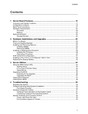
... 1 Server Board Features 15 Connector and Header Locations 17 Configuration Jumpers ...18 Back Panel Connectors...21 Hardware Requirements ...22 Processor ...22 Memory ...22 Optional Hardware ...24 Storage Devices ...24 2 Hardware Installations and Upgrades 25 Before You Begin ...25... Tools and Supplies Needed 25 Installing and Removing Memory 25 Installing DIMMs...25 Removing DIMMs...27 Installing or Replacing the Processor 28 Installing the Processor 28 Removing a Processor 30 RJ45 Serial Port Configuration 31 Installing a PCI, PCI-X, or PCI-Express* Add-in Card 32 Replacing the...
... 1 Server Board Features 15 Connector and Header Locations 17 Configuration Jumpers ...18 Back Panel Connectors...21 Hardware Requirements ...22 Processor ...22 Memory ...22 Optional Hardware ...24 Storage Devices ...24 2 Hardware Installations and Upgrades 25 Before You Begin ...25... Tools and Supplies Needed 25 Installing and Removing Memory 25 Installing DIMMs...25 Removing DIMMs...27 Installing or Replacing the Processor 28 Installing the Processor 28 Removing a Processor 30 RJ45 Serial Port Configuration 31 Installing a PCI, PCI-X, or PCI-Express* Add-in Card 32 Replacing the...

User Guide
Page 12
Intel® Server Board SE7320VP2 15 Figure 2. Opening Socket Lever 28 Figure 9. Closing Socket Lever 29 Figure 11. Password Recovery Jumper 37 Figure 15. Server Board Connector and Header Locations 17 Figure 3. Installing Heat Sink 30 Figure 12. CMOS Recovery Jumper 38 xii Recovery Jumper Location 18 Figure 4. Inserting Processor... 52 Taiwan Declaration of Conformity (BSMI 52 Korean Compliance (RRL 52 Getting Help ...53 Intel® Server Issue Report Form 55 Figures Figure 1. Serial Port Configuration Jumper Location 19 Figure 5. Back Panel Connectors 21...
Intel® Server Board SE7320VP2 15 Figure 2. Opening Socket Lever 28 Figure 9. Closing Socket Lever 29 Figure 11. Password Recovery Jumper 37 Figure 15. Server Board Connector and Header Locations 17 Figure 3. Installing Heat Sink 30 Figure 12. CMOS Recovery Jumper 38 xii Recovery Jumper Location 18 Figure 4. Inserting Processor... 52 Taiwan Declaration of Conformity (BSMI 52 Korean Compliance (RRL 52 Getting Help ...53 Intel® Server Issue Report Form 55 Figures Figure 1. Serial Port Configuration Jumper Location 19 Figure 5. Back Panel Connectors 21...

User Guide
Page 13
Table 3. Table 8. Table 9. Table 10. Table 7. Table 11. Table 4. Table 5. Contents Server Board Features 16 Recovery Jumper [J1H2, J1H3, J1H5 18 Serial Port Configuration Jumper [J8A3 19 BIOS Select Jumper [J1A4 20 NIC LEDs...21 Processor Support 22 Memory Capacity Support 23 Keyboard Commands 35 Keyboard Commands 48 Product Certification Markings 50 Customer Support Telephone Numbers 53 xiii Tables Table 1. Table 6. Table 2.
Table 3. Table 8. Table 9. Table 10. Table 7. Table 11. Table 4. Table 5. Contents Server Board Features 16 Recovery Jumper [J1H2, J1H3, J1H5 18 Serial Port Configuration Jumper [J8A3 19 BIOS Select Jumper [J1A4 20 NIC LEDs...21 Processor Support 22 Memory Capacity Support 23 Keyboard Commands 35 Keyboard Commands 48 Product Certification Markings 50 Customer Support Telephone Numbers 53 xiii Tables Table 1. Table 6. Table 2.
User Guide
Page 16
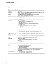
... Features Feature Description Processors Support for up to two Intel® Xeon™ processors with an 800 MT/s MHz front side bus and frequencies starting at 2.8 GHz. Memory Six DIMM slots supporting DDR266MHz or DDR333MHz memory Memory mirroring and memory sparing options Chipset Intel® E7320 chipset, including: ƒ Intel E7320 MCH ƒ Intel 6300ESB ICH...
... Features Feature Description Processors Support for up to two Intel® Xeon™ processors with an 800 MT/s MHz front side bus and frequencies starting at 2.8 GHz. Memory Six DIMM slots supporting DDR266MHz or DDR333MHz memory Memory mirroring and memory sparing options Chipset Intel® E7320 chipset, including: ƒ Intel E7320 MCH ƒ Intel 6300ESB ICH...

User Guide
Page 17
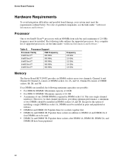
...CC BB Server Board Features F AA Z G Y X H W V U T SR QP N L J I OM K A Serial Port A header K Processor 2 fan header TP00941 U Configuration jumpers B Battery L +12V processor power connector V SATA 1 connector C Full-height PCI slot M Fan board connector W SATA 0 connector D Low-profile PCI slot N Floppy connector Z Power ...header G DIMM sockets Q 100-pin Floppy / Front Panel / AA IDE power connector ATA connector H Processor 1 fan header R Main power connector BB BIOS Select jumper I Processor 1 socket S 50-pin front panel connector CC Chassis intrusion header...
...CC BB Server Board Features F AA Z G Y X H W V U T SR QP N L J I OM K A Serial Port A header K Processor 2 fan header TP00941 U Configuration jumpers B Battery L +12V processor power connector V SATA 1 connector C Full-height PCI slot M Fan board connector W SATA 0 connector D Low-profile PCI slot N Floppy connector Z Power ...header G DIMM sockets Q 100-pin Floppy / Front Panel / AA IDE power connector ATA connector H Processor 1 fan header R Main power connector BB BIOS Select jumper I Processor 1 socket S 50-pin front panel connector CC Chassis intrusion header...
User Guide
Page 22
... GB ƒ A minimum of 2.8 GHz frequency must be installed in DIMM socket 1A. Processor Support Processor Family FSB Frequency Intel® Xeon™ 800 MHz Intel® Xeon™ 800 MHz Intel® Xeon™ 800 MHz Intel® Xeon™ 800 MHz Intel® Xeon™ 800 MHz Frequency 2.8 GHz 3.0 GHz 3.2 GHz 3.4 GHz 3.6 GHz Memory The...
... GB ƒ A minimum of 2.8 GHz frequency must be installed in DIMM socket 1A. Processor Support Processor Family FSB Frequency Intel® Xeon™ 800 MHz Intel® Xeon™ 800 MHz Intel® Xeon™ 800 MHz Intel® Xeon™ 800 MHz Intel® Xeon™ 800 MHz Frequency 2.8 GHz 3.0 GHz 3.2 GHz 3.4 GHz 3.6 GHz Memory The...

User Guide
Page 25
..., pay close attention to the Safety Information at the beginning of this manual. Observe the safety and ESD precautions at the beginning of the board. Intel® Server Board SE7320VP2 User Guide 25 Tools and Supplies Needed ƒ Phillips* (cross head) screwdriver (#1 bit and #2 bit) ƒ Flat-head screwdriver if replacing...
..., pay close attention to the Safety Information at the beginning of this manual. Observe the safety and ESD precautions at the beginning of the board. Intel® Server Board SE7320VP2 User Guide 25 Tools and Supplies Needed ƒ Phillips* (cross head) screwdriver (#1 bit and #2 bit) ƒ Flat-head screwdriver if replacing...

User Guide
Page 28
..." for instructions on removing the server's cover 5. ESD and handling processors: Reduce the risk of compatible processor(s). Installing the Processor To install a processor, follow these instructions: 1. Locate the processor socket and raise the socket handle completely (see Figure 8). TP00763 Figure... Remove the server's cover. Hardware Installations and Upgrades Installing or Replacing the Processor CAUTIONS Processor must be appropriate: You may damage the server board if you install a processor that accompanied your server. Keep part of this book. 2. Disconnect the...
..." for instructions on removing the server's cover 5. ESD and handling processors: Reduce the risk of compatible processor(s). Installing the Processor To install a processor, follow these instructions: 1. Locate the processor socket and raise the socket handle completely (see Figure 8). TP00763 Figure... Remove the server's cover. Hardware Installations and Upgrades Installing or Replacing the Processor CAUTIONS Processor must be appropriate: You may damage the server board if you install a processor that accompanied your server. Keep part of this book. 2. Disconnect the...

User Guide
Page 29
A B A TP00764 Figure 9. Align the pins of the processor with the socket, and insert the processor into the socket. ✏ NOTE Make sure the alignment triangle mark and the alignment triangle cutout align correctly. TP00765 Figure 10. Lower the socket lever completely. Inserting Processor 7. Closing Socket Lever 29 Hardware Installations and Upgrades 6.
A B A TP00764 Figure 9. Align the pins of the processor with the socket, and insert the processor into the socket. ✏ NOTE Make sure the alignment triangle mark and the alignment triangle cutout align correctly. TP00765 Figure 10. Lower the socket lever completely. Inserting Processor 7. Closing Socket Lever 29 Hardware Installations and Upgrades 6.

User Guide
Page 30
... accompanied your server chassis for instructions on removing the server's cover. 5. Set the heat sink over the processor, lining up the four captive screws with the four posts surrounding the processor. 3. Do not fully tighten one screw, then the screw located diagonally to the server. Reinstall and reconnect...). Use caution when you unpack the heat sink so you removed or disconnected to break the seal between the heat sink and the processor. 30 Gradually and equally tighten each captive screw until each is firmly tightened. Observe the safety and ESD precautions at the beginning of...
... accompanied your server chassis for instructions on removing the server's cover. 5. Set the heat sink over the processor, lining up the four captive screws with the four posts surrounding the processor. 3. Do not fully tighten one screw, then the screw located diagonally to the server. Reinstall and reconnect...). Use caution when you unpack the heat sink so you removed or disconnected to break the seal between the heat sink and the processor. 30 Gradually and equally tighten each captive screw until each is firmly tightened. Observe the safety and ESD precautions at the beginning of...

User Guide
Page 31
...your server board to support either a DSR signal or a DCD signal. See Figure 12. 6. Doing so could damage the processor. 9. Remove the processor. 11. RJ45 Serial Port Configuration The RJ45 serial port connector can be changed. Use the following instructions to configure your server ...chassis for the serial port. Move the jumper from the processor. Changing the Serial Port Configuration 31 To change the configuration to cover pins 2 and 4. Turn off the server. 3. Remove the...
...your server board to support either a DSR signal or a DCD signal. See Figure 12. 6. Doing so could damage the processor. 9. Remove the processor. 11. RJ45 Serial Port Configuration The RJ45 serial port connector can be changed. Use the following instructions to configure your server ...chassis for the serial port. Move the jumper from the processor. Changing the Serial Port Configuration 31 To change the configuration to cover pins 2 and 4. Turn off the server. 3. Remove the...

User Guide
Page 40
... and Software" for links to the manufacturer's documentation that occur at the AC source. ‰ Are all cables correctly connected and secured? ‰ Are the processors fully seated in their sockets on the server board? ‰ Are all standoffs in the proper location and not touching any components, causing a potential short...
... and Software" for links to the manufacturer's documentation that occur at the AC source. ‰ Are all cables correctly connected and secured? ‰ Are the processors fully seated in their sockets on the server board? ‰ Are all standoffs in the proper location and not touching any components, causing a potential short...

User Guide
Page 42
... memory DIMMs comply with the system requirements. ‰ Make sure the memory DIMMs have been populated according to the system requirements. ‰ Remove the processor(s) and re-seat them. ‰ Make sure the chassis standoffs are problems with the system requirements. ‰ Make sure the... been populated according to the system requirements. ‰ Remove the memory DIMMs and re-seat them. ‰ Make sure the processor(s) comply with application software. ƒ The bootable CD-ROM is it turned on? ‰ Remove all add-in one , is not detected. Troubleshooting Specific Problems...
... memory DIMMs comply with the system requirements. ‰ Make sure the memory DIMMs have been populated according to the system requirements. ‰ Remove the processor(s) and re-seat them. ‰ Make sure the chassis standoffs are problems with the system requirements. ‰ Make sure the... been populated according to the system requirements. ‰ Remove the memory DIMMs and re-seat them. ‰ Make sure the processor(s) comply with application software. ƒ The bootable CD-ROM is it turned on? ‰ Remove all add-in one , is not detected. Troubleshooting Specific Problems...

User Guide
Page 43
... following : ‰ Is the keyboard functioning? Test it switched to the system requirements. ‰ Remove the processor(s) and re-seat them . ‰ Make sure the processor(s) comply with the system requirements. ‰ Make sure the processor(s) have been populated according to the system requirements. ‰ Remove the memory DIMMs and re-seat them .
... following : ‰ Is the keyboard functioning? Test it switched to the system requirements. ‰ Remove the processor(s) and re-seat them . ‰ Make sure the processor(s) comply with the system requirements. ‰ Make sure the processor(s) have been populated according to the system requirements. ‰ Remove the memory DIMMs and re-seat them .


