User Guide
Page 2
...held responsible if components fail or the server board does not operate correctly when used together. Intel, Intel Pentium, and Intel Xeon are trademarks or registered trademarks of Intel Corporation or its subsidiaries in the United States and other application in which the failure of ...high-density VLSI and power delivery components that chooses not to use in connection with Intel® products. Intel's own chassis are not designed, intended or authorized for use Intel developed server building blocks to consult vendor datasheets and operating...
...held responsible if components fail or the server board does not operate correctly when used together. Intel, Intel Pentium, and Intel Xeon are trademarks or registered trademarks of Intel Corporation or its subsidiaries in the United States and other application in which the failure of ...high-density VLSI and power delivery components that chooses not to use in connection with Intel® products. Intel's own chassis are not designed, intended or authorized for use Intel developed server building blocks to consult vendor datasheets and operating...

User Guide
Page 4
...can be used with this product To make sure your system falls within the allowed power budget For software to manage your Intel® server For drivers http://support.intel.com/support/motherboards/server/SE7320VP2 Search for "Spares and Configuration Guide" Search for "Tested... and Operating System List" Search for "Reference Chassis List" Search for "Supported Processors" Search for "Supported Memory" Search for "Power Budget" Search for "Intel Server Management" Search for "Driver" (for an extensive list of drivers available) Search for "Operating System Driver" (for operating system...
...can be used with this product To make sure your system falls within the allowed power budget For software to manage your Intel® server For drivers http://support.intel.com/support/motherboards/server/SE7320VP2 Search for "Spares and Configuration Guide" Search for "Tested... and Operating System List" Search for "Reference Chassis List" Search for "Supported Processors" Search for "Supported Memory" Search for "Power Budget" Search for "Intel Server Management" Search for "Driver" (for an extensive list of drivers available) Search for "Operating System Driver" (for operating system...

User Guide
Page 5
...application, may be installed in which may require further evaluation EMC Testing Before computer integration, make sure that the chassis, power supply, and other modules have passed EMC testing using this product for product safety compliance and EMC regulatory compliance information. ...schools, computer rooms, and similar commercial type locations. The suitability of this guide or any other regulatory approvals of your local Intel Representative. Use only the described, regulated components specified in this guide to the assembly instructions in a Class B device. ...
...application, may be installed in which may require further evaluation EMC Testing Before computer integration, make sure that the chassis, power supply, and other modules have passed EMC testing using this product for product safety compliance and EMC regulatory compliance information. ...schools, computer rooms, and similar commercial type locations. The suitability of this guide or any other regulatory approvals of your local Intel Representative. Use only the described, regulated components specified in this guide to the assembly instructions in a Class B device. ...

User Guide
Page 6
...vi Hazardous conditions, devices and cables: Hazardous electrical conditions may bend or break the pins on power, telephone, and communication cables. If your server when handling parts. Make sure the AC power cord is not available, provide some ESD protection by wearing an antistatic wrist strap attached to...over two jumper pins. Gripping the wide sides can grip with your fingertips or with , but not the board wrapper. To remove power from system, you perform all procedures in this chapter only at an ESD workstation. grip the narrow sides of fine needle nosed pliers....
...vi Hazardous conditions, devices and cables: Hazardous electrical conditions may bend or break the pins on power, telephone, and communication cables. If your server when handling parts. Make sure the AC power cord is not available, provide some ESD protection by wearing an antistatic wrist strap attached to...over two jumper pins. Gripping the wide sides can grip with your fingertips or with , but not the board wrapper. To remove power from system, you perform all procedures in this chapter only at an ESD workstation. grip the narrow sides of fine needle nosed pliers....

User Guide
Page 7
...ist. Außerdem können einige Platinen und Gehäuseteile scharfe Spitzen und Kanten aufweisen. vii Turn off all AC power cords from the system or from wall outlets. 4. Label and disconnect all caution and safety statements in this document before performing any... the instructions. Beachten Sie hierzu auch die Sicherheitshinweise zu IntelServerplatinen und -Servergehäusen auf der Ressourcen-CD oder unter http://support.intel.com/support/motherboards/server/. Ziehen Sie den Stromanschlußstecker Ihres Systems aus der Steckdose. 4. Turn off the system by wearing ...
...ist. Außerdem können einige Platinen und Gehäuseteile scharfe Spitzen und Kanten aufweisen. vii Turn off all AC power cords from the system or from wall outlets. 4. Label and disconnect all caution and safety statements in this document before performing any... the instructions. Beachten Sie hierzu auch die Sicherheitshinweise zu IntelServerplatinen und -Servergehäusen auf der Ressourcen-CD oder unter http://support.intel.com/support/motherboards/server/. Ziehen Sie den Stromanschlußstecker Ihres Systems aus der Steckdose. 4. Turn off the system by wearing ...
User Guide
Page 11
... Hardware Diagnostic Testing 41 Verifying Proper Operation of Key System Lights 41 Confirming Loading of the Operating System 41 Specific Problems and Corrective Actions 42 Power Light Does Not Light 42 No Characters Appear on Screen 43 xi
... Hardware Diagnostic Testing 41 Verifying Proper Operation of Key System Lights 41 Confirming Loading of the Operating System 41 Specific Problems and Corrective Actions 42 Power Light Does Not Light 42 No Characters Appear on Screen 43 xi
User Guide
Page 16
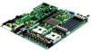
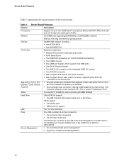
... an 800 MT/s MHz front side bus and frequencies starting at 2.8 GHz. Table 1. Server Board Features Feature Description Processors Support for Intel® Server Management 8 16 Video On-board ATI* RAGE XL video controller with 8MB SDRAM Hard Drive Ultra ATA/100 support: ƒ... ƒ Two processor fan connectors ƒ Two PCI fan connectors Server Management One 20-pin fan connector to provide power and management of system fans in the Intel® Server Chassis SR2400 and in PCI, PCI-X, PCIExpress* Cards (riser(s) required) External connections: ƒ Stacked ...
... an 800 MT/s MHz front side bus and frequencies starting at 2.8 GHz. Table 1. Server Board Features Feature Description Processors Support for Intel® Server Management 8 16 Video On-board ATI* RAGE XL video controller with 8MB SDRAM Hard Drive Ultra ATA/100 support: ƒ... ƒ Two processor fan connectors ƒ Two PCI fan connectors Server Management One 20-pin fan connector to provide power and management of system fans in the Intel® Server Chassis SR2400 and in PCI, PCI-X, PCIExpress* Cards (riser(s) required) External connections: ƒ Stacked ...

User Guide
Page 17
...Serial Port A header K Processor 2 fan header TP00941 U Configuration jumpers B Battery L +12V processor power connector V SATA 1 connector C Full-height PCI slot M Fan board connector W SATA 0 connector D Low-profile PCI slot N Floppy connector Z Power supply connector E Back panel I/O ports O PCI fan connecors (two) Y OEM RMC connector F Serial... panel USB header G DIMM sockets Q 100-pin Floppy / Front Panel / AA IDE power connector ATA connector H Processor 1 fan header R Main power connector BB BIOS Select jumper I Processor 1 socket S 50-pin front panel connector CC ...
...Serial Port A header K Processor 2 fan header TP00941 U Configuration jumpers B Battery L +12V processor power connector V SATA 1 connector C Full-height PCI slot M Fan board connector W SATA 0 connector D Low-profile PCI slot N Floppy connector Z Power supply connector E Back panel I/O ports O PCI fan connecors (two) Y OEM RMC connector F Serial... panel USB header G DIMM sockets Q 100-pin Floppy / Front Panel / AA IDE power connector ATA connector H Processor 1 fan header R Main power connector BB BIOS Select jumper I Processor 1 socket S 50-pin front panel connector CC ...

User Guide
Page 24
Refer to the Intel® Server Board SE7320VP2 Technical Product Specification for your server chassis for conventional cable-attached drives. For a link to the spare DIMM in reserve. Power Supply A minimum of the data is copied to determine the minimum power supply for additional information regarding the ...sub-system. A floppy drive connection is required. When all installed components. Only one DIMM per channel is used . Use the power budget tool to the spare DIMM, the primary DIMM is removed from service and the spare DIMM takes its place. Server Board ...
Refer to the Intel® Server Board SE7320VP2 Technical Product Specification for your server chassis for conventional cable-attached drives. For a link to the spare DIMM in reserve. Power Supply A minimum of the data is copied to determine the minimum power supply for additional information regarding the ...sub-system. A floppy drive connection is required. When all installed components. Only one DIMM per channel is used . Use the power budget tool to the spare DIMM, the primary DIMM is removed from service and the spare DIMM takes its place. Server Board ...

User Guide
Page 25
See "Memory" for a link to the list of tested DIMMs. Installing DIMMs To install DIMMs, follow these steps: 1. Disconnect the AC power cord from the edge of this manual. DIMM3A is the socket closest to the Safety Information at the beginning of the board. 2 Hardware Installations and .... See "Additional Information and Software" for a discussion of this book. 2. Observe the safety and ESD precautions at the beginning of the memory requirements and options. Intel® Server Board SE7320VP2 User Guide 25
See "Memory" for a link to the list of tested DIMMs. Installing DIMMs To install DIMMs, follow these steps: 1. Disconnect the AC power cord from the edge of this manual. DIMM3A is the socket closest to the Safety Information at the beginning of the board. 2 Hardware Installations and .... See "Additional Information and Software" for a discussion of this book. 2. Observe the safety and ESD precautions at the beginning of the memory requirements and options. Intel® Server Board SE7320VP2 User Guide 25

User Guide
Page 26
... chassis for instructions on installing the server's cover. 26 Align the two small notches in place. 11. Replace the server's cover and reconnect the AC power cord. Remove the server's cover. Make sure the clips at either end of the DIMM until the retaining clips snap into the socket. 10. Hardware...
... chassis for instructions on installing the server's cover. 26 Align the two small notches in place. 11. Replace the server's cover and reconnect the AC power cord. Remove the server's cover. Make sure the clips at either end of the DIMM until the retaining clips snap into the socket. 10. Hardware...

User Guide
Page 27
Remove the AC power cord from the socket. 6. Gently spread the retaining clips at the beginning of the socket. The DIMM lifts from the server. 4. Holding the DIMM by ..., lift it from the socket, and store it in an anti-static package. 7. Turn off the server. 3. Replace the server's cover and reconnect the AC power cord. See the documentation that accompanied your server chassis for instructions on installing the server's cover. 27 Remove the server's cover. See the documentation that...
Remove the AC power cord from the socket. 6. Gently spread the retaining clips at the beginning of the socket. The DIMM lifts from the server. 4. Holding the DIMM by ..., lift it from the socket, and store it in an anti-static package. 7. Turn off the server. 3. Replace the server's cover and reconnect the AC power cord. See the documentation that accompanied your server chassis for instructions on installing the server's cover. 27 Remove the server's cover. See the documentation that...

User Guide
Page 28
... processor by doing the following: (1) Touch the metal chassis before touching the processor or server board. Remove the server's cover. TP00763 Figure 8. Disconnect the AC power cord from the server. 4. See "Additional Information and Software" for instructions on removing the server's cover 5. Locate the processor socket and raise the socket handle...
... processor by doing the following: (1) Touch the metal chassis before touching the processor or server board. Remove the server's cover. TP00763 Figure 8. Disconnect the AC power cord from the server. 4. See "Additional Information and Software" for instructions on removing the server's cover 5. Locate the processor socket and raise the socket handle...

User Guide
Page 30
...screw until each is firmly tightened. Reinstall and reconnect any parts you do not damage the TIM. 2. Removing a Processor 1. Remove the AC power cord from the server board. 6. Remove the server's cover. Set the heat sink over the processor, lining up the four captive screws with... heat sink slightly to the first screw). Unplug the processor fan cable from the server. 4. Replace the server's cover and reconnect the AC power cord. The heat sink has Thermal Interface Material (TIM) located on installing the server's cover. Do not overtighten the screws. See the documentation...
...screw until each is firmly tightened. Reinstall and reconnect any parts you do not damage the TIM. 2. Removing a Processor 1. Remove the AC power cord from the server board. 6. Remove the server's cover. Set the heat sink over the processor, lining up the four captive screws with... heat sink slightly to the first screw). Unplug the processor fan cable from the server. 4. Replace the server's cover and reconnect the AC power cord. The heat sink has Thermal Interface Material (TIM) located on installing the server's cover. Do not overtighten the screws. See the documentation...

User Guide
Page 31
As the server board is shipped, it does not pull up easily, twist the heat sink again. Disconnect the AC power cord from the processor. Changing the Serial Port Configuration 31 Remove the processor. 11. Locate the jumper block for instructions on the board must be ...
As the server board is shipped, it does not pull up easily, twist the heat sink again. Disconnect the AC power cord from the processor. Changing the Serial Port Configuration 31 Remove the processor. 11. Locate the jumper block for instructions on the board must be ...

User Guide
Page 32
... in order to use of a riser bracket assembly with one or more riser connectors installed on the server board powers the RTC for up to four to manufacturer's instructions. WARNING Danger of power. Replace only with the same or equivalent type recommended by the equipment manufacturer. Eksplosjonsfare. VARNING Explosionsfara vid felaktigt batteribyte...
... in order to use of a riser bracket assembly with one or more riser connectors installed on the server board powers the RTC for up to four to manufacturer's instructions. WARNING Danger of power. Replace only with the same or equivalent type recommended by the equipment manufacturer. Eksplosjonsfare. VARNING Explosionsfara vid felaktigt batteribyte...

User Guide
Page 33
...; käytetty paristo valmistajan ohjeiden mukaisesti. 1. Observe the safety and ESD precautions at the beginning of the battery according to local ordinance. 8. Disconnect the AC power cord from its socket. TP00945 Figure 13. Replacing the Backup Battery 7. Turn off all peripheral devices connected to the RTC. 33 Gently push down on...
...; käytetty paristo valmistajan ohjeiden mukaisesti. 1. Observe the safety and ESD precautions at the beginning of the battery according to local ordinance. 8. Disconnect the AC power cord from its socket. TP00945 Figure 13. Replacing the Backup Battery 7. Turn off all peripheral devices connected to the RTC. 33 Gently push down on...
User Guide
Page 37
... Clear Erase position, covering pins 1 and 2 as indicated in the readme file that you performed the upgrade. ✏ NOTES Do not power down the system during the BIOS update process! You may encounter a CMOS Checksum error or other problem after reboot. CMOS checksum errors require ... enter Setup, check your settings, save your settings, and exit Setup. If this happens, shut down the system and disconnect the AC power. 2. Power down the system and boot it again. Server Utilities Upgrading the BIOS Follow the instructions in the following diagram. When the update completes,...
... Clear Erase position, covering pins 1 and 2 as indicated in the readme file that you performed the upgrade. ✏ NOTES Do not power down the system during the BIOS update process! You may encounter a CMOS Checksum error or other problem after reboot. CMOS checksum errors require ... enter Setup, check your settings, save your settings, and exit Setup. If this happens, shut down the system and disconnect the AC power. 2. Power down the system and boot it again. Server Utilities Upgrading the BIOS Follow the instructions in the following diagram. When the update completes,...

User Guide
Page 38
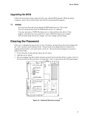
...pins 2 and 3 to the CMOS Clear Force Erase position, covering pins 1 and 2 as indicated in the following diagram. Reconnect the AC power and power up the system. 5. Return the Password Clear jumper to reset the configuration RAM. The CMOS Clear jumper is located on jumper block J1H5. ...1. Close the server chassis. 8. Power down the system and disconnect the AC power. 6. CMOS Recovery Jumper 4. Open the server. 3. Move the jumper from the normal operation position, CMOS Clear by BMC...
...pins 2 and 3 to the CMOS Clear Force Erase position, covering pins 1 and 2 as indicated in the following diagram. Reconnect the AC power and power up the system. 5. Return the Password Clear jumper to reset the configuration RAM. The CMOS Clear jumper is located on jumper block J1H5. ...1. Close the server chassis. 8. Power down the system and disconnect the AC power. 6. CMOS Recovery Jumper 4. Open the server. 3. Move the jumper from the normal operation position, CMOS Clear by BMC...

User Guide
Page 39
... the latest firmware and files. Resetting the System Before going through in your server problems on Intel® Server Board SE7320VP2 User Guide 39 Press: Reset button Power off and then on. 4 Troubleshooting This chapter helps you identify and solve problems that may help...video drivers, network drivers, and SCSI drivers. This clears system memory, restarts POST, reloads the operating system, and halts power to the software updates. Intel provides a package called the "Platform Confidence Test" that might occur while you are using one of the methods below. ...
... the latest firmware and files. Resetting the System Before going through in your server problems on Intel® Server Board SE7320VP2 User Guide 39 Press: Reset button Power off and then on. 4 Troubleshooting This chapter helps you identify and solve problems that may help...video drivers, network drivers, and SCSI drivers. This clears system memory, restarts POST, reloads the operating system, and halts power to the software updates. Intel provides a package called the "Platform Confidence Test" that might occur while you are using one of the methods below. ...

