
User Guide
Page 1
Intel® Server Board SE7320SP2 / SE7525GP2 User Guide A Guide for Technically Qualified Assemblers of Intel® Identified Subassemblies/Products Order Number: C62033-002
Intel® Server Board SE7320SP2 / SE7525GP2 User Guide A Guide for Technically Qualified Assemblers of Intel® Identified Subassemblies/Products Order Number: C62033-002
User Guide
Page 3
... ƒ SC5275-E You may need or want to identify the source of the Server Boards SE7320SP2 and SE7525GP2. Chapter 2 provides instructions on using the Intel® Server Board SE7320SP2 or SE7525GP2. Chapter 3 provides instructions on adding and replacing components. Product Accessories These server boards are compatible with your server: Processors, memory DIMMs, hard drive, floppy drive, CD-ROM or DVD-ROM drive...
... ƒ SC5275-E You may need or want to identify the source of the Server Boards SE7320SP2 and SE7525GP2. Chapter 2 provides instructions on using the Intel® Server Board SE7320SP2 or SE7525GP2. Chapter 3 provides instructions on adding and replacing components. Product Accessories These server boards are compatible with your server: Processors, memory DIMMs, hard drive, floppy drive, CD-ROM or DVD-ROM drive...

User Guide
Page 4
... repair information Use this Document or Software Technical Product Specification Intel® Server Board SE7320SP2 Quick Start User's Guide in the product box Intel® Server Board SE7525GP2 Quick Start User's Guide in the search field at http://support.intel.com/support/motherboards/server/SE7320SP2/ and Accessories or other Intel server products Hardware (peripheral boards, adapter cards) and operating systems that have been tested...
... repair information Use this Document or Software Technical Product Specification Intel® Server Board SE7320SP2 Quick Start User's Guide in the product box Intel® Server Board SE7525GP2 Quick Start User's Guide in the search field at http://support.intel.com/support/motherboards/server/SE7320SP2/ and Accessories or other Intel server products Hardware (peripheral boards, adapter cards) and operating systems that have been tested...

User Guide
Page 5
... not result in this guide. Otherwise, personal injury or equipment damage can result. This is sold. Warnings System power on power, telephone, and communication cables. Intel Server Board SE7320SP2 / SE7525GP2 User Guide v Hazardous conditions, devices and cables: Hazardous electrical conditions may be installed in which may require further evaluation EMC Testing Before computer integration, make...
... not result in this guide. Otherwise, personal injury or equipment damage can result. This is sold. Warnings System power on power, telephone, and communication cables. Intel Server Board SE7320SP2 / SE7525GP2 User Guide v Hazardous conditions, devices and cables: Hazardous electrical conditions may be installed in which may require further evaluation EMC Testing Before computer integration, make...

User Guide
Page 6
...Label and disconnect all peripheral devices connected to chassis ground any of the system, follow these steps: 1. Intel Server Board SE7320SP2 / SE7525GP2 User Guide vi Installing or removing jumpers: A jumper is not available, provide some board and chassis parts. when handling components. 6. Do not operate the system with the chassis covers removed. ...: ESD can grip with your fingertips or with a pair of the jumper with the pliers, never the wide sides. See also Intel Server Boards and Server Chassis Safety Information on the Resource CD and/or at an ESD workstation.
...Label and disconnect all peripheral devices connected to chassis ground any of the system, follow these steps: 1. Intel Server Board SE7320SP2 / SE7525GP2 User Guide vi Installing or removing jumpers: A jumper is not available, provide some board and chassis parts. when handling components. 6. Do not operate the system with the chassis covers removed. ...: ESD can grip with your fingertips or with a pair of the jumper with the pliers, never the wide sides. See also Intel Server Boards and Server Chassis Safety Information on the Resource CD and/or at an ESD workstation.

User Guide
Page 11
... and Component Locations 18 Configuration and BIOS Select Jumpers 19 Back Panel Connectors...20 Making Connections to the Server Board 21 Hardware Requirements ...22 2 Server Board Installations and Upgrades 23 Before You Begin ...23 Tools and Supplies Needed 23 Installing and Removing Memory 23 Installing DIMMs...23 Removing DIMMs...25 Installing ... 41 Diskette Drive Activity Light Does Not Light 42 CD-ROM Drive or DVD-ROM Drive Activity Light Does Not Light 42 Cannot Connect to a Server 42 Intel Server Board SE7320SP2 / SE7525GP2 User Guide 11
... and Component Locations 18 Configuration and BIOS Select Jumpers 19 Back Panel Connectors...20 Making Connections to the Server Board 21 Hardware Requirements ...22 2 Server Board Installations and Upgrades 23 Before You Begin ...23 Tools and Supplies Needed 23 Installing and Removing Memory 23 Installing DIMMs...23 Removing DIMMs...25 Installing ... 41 Diskette Drive Activity Light Does Not Light 42 CD-ROM Drive or DVD-ROM Drive Activity Light Does Not Light 42 Cannot Connect to a Server 42 Intel Server Board SE7320SP2 / SE7525GP2 User Guide 11

User Guide
Page 12
...) ...53 Industry Canada (ICES-003 54 Europe (CE Declaration of Conformity 54 Taiwan Declaration of Conformity (BSMI 54 Korean Compliance (RRL 54 Getting Help ...55 Intel® Server Issue Report Form 57 Intel Server Board SE7320SP2 / SE7525GP2 User Guide 12
...) ...53 Industry Canada (ICES-003 54 Europe (CE Declaration of Conformity 54 Taiwan Declaration of Conformity (BSMI 54 Korean Compliance (RRL 54 Getting Help ...55 Intel® Server Issue Report Form 57 Intel Server Board SE7320SP2 / SE7525GP2 User Guide 12

User Guide
Page 13
.... Intel® Server Board SE7320SP2 15 Figure 2. Replacing the Battery 30 Tables Table 1. Table 4. Table 5. Server Board SE7320SP2 Features 16 Server Board SE7525GP2 Features 17 Configuration Jumper [J17 19 BIOS Select Jumper [J29 19 NIC LEDs...20 Keyboard Commands 31 BIOS Error Messages 47 Beep Codes 48 BIOS Recovery Beep Codes 49 Product Certification Markings 52 Intel Server Board SE7320SP2 / SE7525GP2 User Guide 13 Intel Server Board SE7320SP2 / SE7525GP2 Layout...
.... Intel® Server Board SE7320SP2 15 Figure 2. Replacing the Battery 30 Tables Table 1. Table 4. Table 5. Server Board SE7320SP2 Features 16 Server Board SE7525GP2 Features 17 Configuration Jumper [J17 19 BIOS Select Jumper [J29 19 NIC LEDs...20 Keyboard Commands 31 BIOS Error Messages 47 Beep Codes 48 BIOS Recovery Beep Codes 49 Product Certification Markings 52 Intel Server Board SE7320SP2 / SE7525GP2 User Guide 13 Intel Server Board SE7320SP2 / SE7525GP2 Layout...

User Guide
Page 15
.../100/1000 Mbits/sec Ethernet LAN connectivity and a 4-port Silicon Image* Serial ATA controller: SI3124. Intel® Server Board SE7320SP2 Intel Server Board SE7320SP2 / SE7525GP2 User Guide 15 1 Server Board Features This chapter briefly describes the main features of important components and connections on the server board. ƒ The server boards SE7320SP2 and SE7525GP2 include dual-channel Serial ATA and dual- RAID 0 and 1 support is shown below.
.../100/1000 Mbits/sec Ethernet LAN connectivity and a 4-port Silicon Image* Serial ATA controller: SI3124. Intel® Server Board SE7320SP2 Intel Server Board SE7320SP2 / SE7525GP2 User Guide 15 1 Server Board Features This chapter briefly describes the main features of important components and connections on the server board. ƒ The server boards SE7320SP2 and SE7525GP2 include dual-channel Serial ATA and dual- RAID 0 and 1 support is shown below.

User Guide
Page 16
... displaying POST Codes Intel Server Board SE7320SP2 / SE7525GP2 User Guide 16 Server Board SE7320SP2 Features Feature Description Processors Memory Chipset Support for two Intel® Xeon™ processors in two 604-pin Intel Xeon processor sockets with an 800 MHz system bus ƒ Four 184-pin DDR SDRAM Dual Inline Memory Module (DIMM) sockets ƒ Support for up to 8 GB Registered ECC system memory...
... displaying POST Codes Intel Server Board SE7320SP2 / SE7525GP2 User Guide 16 Server Board SE7320SP2 Features Feature Description Processors Memory Chipset Support for two Intel® Xeon™ processors in two 604-pin Intel Xeon processor sockets with an 800 MHz system bus ƒ Four 184-pin DDR SDRAM Dual Inline Memory Module (DIMM) sockets ƒ Support for up to 8 GB Registered ECC system memory...

User Guide
Page 17
... (one x4 PCI-Express; Server Board SE7525GP2 Features Feature Description Processors Memory Chipset Support for two Intel® Xeon™ processors in two 604-pin Intel Xeon processor sockets with an 800 MHz system bus ƒ Four 184-pin DDR SDRAM Dual Inline Memory Module (DIMM) sockets ƒ Support for up to 8 GB Registered ECC system memory ƒ Support...
... (one x4 PCI-Express; Server Board SE7525GP2 Features Feature Description Processors Memory Chipset Support for two Intel® Xeon™ processors in two 604-pin Intel Xeon processor sockets with an 800 MHz system bus ƒ Four 184-pin DDR SDRAM Dual Inline Memory Module (DIMM) sockets ƒ Support for up to 8 GB Registered ECC system memory ƒ Support...

User Guide
Page 18
Intel Server Board SE7320SP2 / SE7525GP2 Layout Intel Server Board SE7320SP2 / SE7525GP2 User Guide 18 SE7525GP2 server board only Z: Primary and Secondary ATA Connectors G: System Fan Header 2 AA: System Fan Header 3 H: Rear I/O (see figure 4 for details) BB: System Fan Header 4 I JK L M HH GG FF EE DD CC BB Z AA Y WU XV T R S QP ON TP00680 Server Board...CPU Power Connector GG: LCD Header N: Processor Socket 1 HH: SATA B1, B2, B3, B4 Connectors; SE7320SP2 LX server board only O: Processor 1 Fan Header II: Battery P: Processor Socket 2 JJ: Jumper Block Q: System Fan ...
Intel Server Board SE7320SP2 / SE7525GP2 Layout Intel Server Board SE7320SP2 / SE7525GP2 User Guide 18 SE7525GP2 server board only Z: Primary and Secondary ATA Connectors G: System Fan Header 2 AA: System Fan Header 3 H: Rear I/O (see figure 4 for details) BB: System Fan Header 4 I JK L M HH GG FF EE DD CC BB Z AA Y WU XV T R S QP ON TP00680 Server Board...CPU Power Connector GG: LCD Header N: Processor Socket 1 HH: SATA B1, B2, B3, B4 Connectors; SE7320SP2 LX server board only O: Processor 1 Fan Header II: Battery P: Processor Socket 2 JJ: Jumper Block Q: System Fan ...
User Guide
Page 19
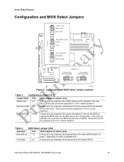
...These pins should be jumpered on the next reset. Intel Server Board SE7320SP2 / SE7525GP2 User Guide 19 Configuration Jumper [J17] Jumper Name Pins What happens at system reset... Force Boot 2-3 If these pins are jumpered, the board will attempt to recover the BIOS by loading the...Password Clear 6-7 If these pins are jumpered, administrator and user passwords will boot off of bank 0 BIOS) 23 23 TP00681 Figure 3. Server Board Features Configuration and BIOS Select Jumpers CMOS CLEAR BMC Control 2 Force Erase 3 4 5 PASSWORD CLEAR J17 (1x11) Protect 6 Erase 7 ...
...These pins should be jumpered on the next reset. Intel Server Board SE7320SP2 / SE7525GP2 User Guide 19 Configuration Jumper [J17] Jumper Name Pins What happens at system reset... Force Boot 2-3 If these pins are jumpered, the board will attempt to recover the BIOS by loading the...Password Clear 6-7 If these pins are jumpered, administrator and user passwords will boot off of bank 0 BIOS) 23 23 TP00681 Figure 3. Server Board Features Configuration and BIOS Select Jumpers CMOS CLEAR BMC Control 2 Force Erase 3 4 5 PASSWORD CLEAR J17 (1x11) Protect 6 Erase 7 ...

User Guide
Page 20
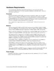
NIC 2 (1Gbit. SE7320SP2 LX server board only) H. Video G. Table 5. Back Panel Connectors C E A GH B A. Keyboard D F TP00682 E. NIC LEDs NIC NIC1 / NIC2 (Gigabit) LED Color Left LED Right LED LED State Off Solid ...) Figure 4. Serial port A F. Back Panel Connectors The NIC LEDs at the right and left LED is on or blinking) 100 Mbps connection 1000 Mbps connection Intel Server Board SE7320SP2 / SE7525GP2 User Guide 20 USB 1 B. Mouse D.
NIC 2 (1Gbit. SE7320SP2 LX server board only) H. Video G. Table 5. Back Panel Connectors C E A GH B A. Keyboard D F TP00682 E. NIC LEDs NIC NIC1 / NIC2 (Gigabit) LED Color Left LED Right LED LED State Off Solid ...) Figure 4. Serial port A F. Back Panel Connectors The NIC LEDs at the right and left LED is on or blinking) 100 Mbps connection 1000 Mbps connection Intel Server Board SE7320SP2 / SE7525GP2 User Guide 20 USB 1 B. Mouse D.

User Guide
Page 21
...Power Connector P. Processor 1 Fan Header Q. SATA Connectors I CPU 1 Socket G A. Processor 21 Fan Header T. Server Board Features Making Connections to the Server Board The connections you make all of the front system fans. IPMB Connector TP00683 B. Chassis Intrusion Connector J. Serial B...are installing the board into the Server Chassis SC5275-E, install the hard drive cage before making your Server Board SE7320SP2 / SE7525GP2 into and the components you are installing. You may not need to the Server Board Intel Server Board SE7320SP2 / SE7525GP2 User Guide 21...
...Power Connector P. Processor 1 Fan Header Q. SATA Connectors I CPU 1 Socket G A. Processor 21 Fan Header T. Server Board Features Making Connections to the Server Board The connections you make all of the front system fans. IPMB Connector TP00683 B. Chassis Intrusion Connector J. Serial B...are installing the board into the Server Chassis SC5275-E, install the hard drive cage before making your Server Board SE7320SP2 / SE7525GP2 into and the components you are installing. You may not need to the Server Board Intel Server Board SE7320SP2 / SE7525GP2 User Guide 21...
User Guide
Page 22
...performance and dual-channel interleave operation, a minimum of the Xeon processor are designed to be identical (same manufacturer, CAS latency, number of DDR266 and DDR333 memory is supported on server boards SE7320SP2 and SE7525GP2. Previous generations of two DIMMs should be populated in DIMM...BIOS supports various DIMM sizes and configurations allowing the banks of memory to support one DIMM, installed in pairs. Intel Server Board SE7320SP2 / SE7525GP2 User Guide 22 Memory DIMM technologies supported are installed in two DIMM banks. Both DIMMS in a bank must meet the...
...performance and dual-channel interleave operation, a minimum of the Xeon processor are designed to be identical (same manufacturer, CAS latency, number of DDR266 and DDR333 memory is supported on server boards SE7320SP2 and SE7525GP2. Previous generations of two DIMMs should be populated in DIMM...BIOS supports various DIMM sizes and configurations allowing the banks of memory to support one DIMM, installed in pairs. Intel Server Board SE7320SP2 / SE7525GP2 User Guide 22 Memory DIMM technologies supported are installed in two DIMM banks. Both DIMMS in a bank must meet the...

User Guide
Page 23
... DIMM population rules, see "Memory." See your server product, pay close attention to the Safety Information at the beginning of the board. Turn off all peripheral devices connected to the processor socket. Locate the DIMM sockets. Intel Server Board SE7320SP2 / SE7525GP2 User Guide 23 See "Safety Information." 2. Turn off the server. 3. Installing DIMMs To install DIMMs, follow these...
... DIMM population rules, see "Memory." See your server product, pay close attention to the Safety Information at the beginning of the board. Turn off all peripheral devices connected to the processor socket. Locate the DIMM sockets. Intel Server Board SE7320SP2 / SE7525GP2 User Guide 23 See "Safety Information." 2. Turn off the server. 3. Installing DIMMs To install DIMMs, follow these...

User Guide
Page 24
...13. Make sure the clips at either end of the DIMM with the keys in the socket (see inset in place. 11. Replace the server's cover. Align the small notch in the bottom edge of the DIMM socket(s) are firmly in Figure 6). 9. Reconnect or replace any external ...the DIMM by the edges, remove it from its anti-static package. 8. Reconnect any internal components you needed to disconnect or remove. 12. Intel Server Board SE7320SP2 / SE7525GP2 User Guide 24 Installing Memory TP00684 6. When the DIMM is inserted, push down on the top edge of the DIMM into place. Attach the ...
...13. Make sure the clips at either end of the DIMM with the keys in the socket (see inset in place. 11. Replace the server's cover. Align the small notch in the bottom edge of the DIMM socket(s) are firmly in Figure 6). 9. Reconnect or replace any external ...the DIMM by the edges, remove it from its anti-static package. 8. Reconnect any internal components you needed to disconnect or remove. 12. Intel Server Board SE7320SP2 / SE7525GP2 User Guide 24 Installing Memory TP00684 6. When the DIMM is inserted, push down on the top edge of the DIMM into place. Attach the ...

User Guide
Page 25
... part of the socket. Observe the safety and ESD precautions at each end of your chassis documentation for instructions. 5. Replace the server's cover. Intel Server Board SE7320SP2 / SE7525GP2 User Guide 25 Remove the server's cover. Reconnect any internal components you needed to install or replace a processor instead of using the instructions that the processors are identical and...
... part of the socket. Observe the safety and ESD precautions at each end of your chassis documentation for instructions. 5. Replace the server's cover. Intel Server Board SE7320SP2 / SE7525GP2 User Guide 25 Remove the server's cover. Reconnect any internal components you needed to install or replace a processor instead of using the instructions that the processors are identical and...

User Guide
Page 26
Lift the socket lever for instructions. 5. Turn off the server. 3. See your system by unplugging the AC power cord. 4. See Figure 7. See "Safety Information." 2. Remove the chassis cover. Installing the ... sure the alignment triangle mark and the alignment triangle cutout align correctly. Turn off all peripheral devices connected to the server. A B OM15042 Figure 7. Align the pins of this book. Remove power from your chassis documentation for the processor. 6. Opening Socket Lever and Attaching Processor Intel Server Board SE7320SP2 / SE7525GP2 User Guide 26
Lift the socket lever for instructions. 5. Turn off the server. 3. See your system by unplugging the AC power cord. 4. See Figure 7. See "Safety Information." 2. Remove the chassis cover. Installing the ... sure the alignment triangle mark and the alignment triangle cutout align correctly. Turn off all peripheral devices connected to the server. A B OM15042 Figure 7. Align the pins of this book. Remove power from your chassis documentation for the processor. 6. Opening Socket Lever and Attaching Processor Intel Server Board SE7320SP2 / SE7525GP2 User Guide 26


