User Guide
Page 3
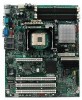
..., and product diagrams to add and replace components on the Intel Entry Server Board SE7210TP1-E. See "Additional Information and Software" for installing or replacing components such as the memory, processor, the battery, and other components you may be required to http://www.support.intel.com/support/motherboards/server/SE7210TP1-E. In this chapter, you identify components and their locations...
..., and product diagrams to add and replace components on the Intel Entry Server Board SE7210TP1-E. See "Additional Information and Software" for installing or replacing components such as the memory, processor, the battery, and other components you may be required to http://www.support.intel.com/support/motherboards/server/SE7210TP1-E. In this chapter, you identify components and their locations...
User Guide
Page 7
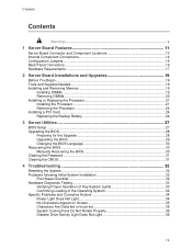
...14 Configuration Jumpers ...15 Back Panel Connectors...16 Hardware Requirements ...17 2 Server Board Installations and Upgrades 19 Before You Begin ...19 Tools and Supplies Needed 19 Installing and Removing Memory 19 Installing DIMMs...19 Removing DIMMs...20 Installing or Replacing the Processor 21... Installing the Processor 21 Removing the Processor 24 Installing a PCI Card ...24 Replacing the Backup Battery 24 3 Server Utilities 27 BIOS Setup ...27 ...
...14 Configuration Jumpers ...15 Back Panel Connectors...16 Hardware Requirements ...17 2 Server Board Installations and Upgrades 19 Before You Begin ...19 Tools and Supplies Needed 19 Installing and Removing Memory 19 Installing DIMMs...19 Removing DIMMs...20 Installing or Replacing the Processor 21... Installing the Processor 21 Removing the Processor 24 Installing a PCI Card ...24 Replacing the Backup Battery 24 3 Server Utilities 27 BIOS Setup ...27 ...
User Guide
Page 9
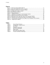
... Processor Fan Connector 23 Figure 12. Installing Memory 20 Figure 7. Installing the Processor in the Processor Socket 21 Figure 8. Connecting the Processor Fan Cable to the Server Board 14 Figure 4. Table 3. Server Board Features 12 Configuration Jumper [J1D1 15 ...Intel® Server Board SE7210TP1-E 11 Figure 2. Attaching the Fan Heat Sink Clips to the Processor Socket 23 Figure 11. Table 7. Table 8. Attaching the Fan Heat Sink Clips to the Processor Socket 22 Figure 10. Replacing the Battery 25 Tables Table 1. Table 2. Intel Server Board SE7210TP1...
... Processor Fan Connector 23 Figure 12. Installing Memory 20 Figure 7. Installing the Processor in the Processor Socket 21 Figure 8. Connecting the Processor Fan Cable to the Server Board 14 Figure 4. Table 3. Server Board Features 12 Configuration Jumper [J1D1 15 ...Intel® Server Board SE7210TP1-E 11 Figure 2. Attaching the Fan Heat Sink Clips to the Processor Socket 23 Figure 11. Table 7. Table 8. Attaching the Fan Heat Sink Clips to the Processor Socket 22 Figure 10. Replacing the Battery 25 Tables Table 1. Table 2. Intel Server Board SE7210TP1...
User Guide
Page 12
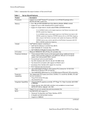
...frequency. - Intel® 827210 chipset, consisting of 800 MHz. - Server Board Features Feature Processors Memory Description Support for an Intel® Pentium® 4 processor in an mPGA478 package with a 800/533/400 MHz system bus ƒ Four 184-pin DDR SDRAM Dual Inline Memory Module (DIMM) sockets ƒ...; 82547EI Platform LAN Connect (PLC) device for 10/100/1000 Mbits/second Ethernet LAN connectivity ƒ One Intel® 82551QM device for SMBIOS continued 12 Intel Server Board SE7210TP1-E User Guide one 64-bit, 66 MHz, 5V) with four bus connectors: ƒ Three PCI-X 64-bit ...
...frequency. - Intel® 827210 chipset, consisting of 800 MHz. - Server Board Features Feature Processors Memory Description Support for an Intel® Pentium® 4 processor in an mPGA478 package with a 800/533/400 MHz system bus ƒ Four 184-pin DDR SDRAM Dual Inline Memory Module (DIMM) sockets ƒ...; 82547EI Platform LAN Connect (PLC) device for 10/100/1000 Mbits/second Ethernet LAN connectivity ƒ One Intel® 82551QM device for SMBIOS continued 12 Intel Server Board SE7210TP1-E User Guide one 64-bit, 66 MHz, 5V) with four bus connectors: ƒ Three PCI-X 64-bit ...
User Guide
Page 17
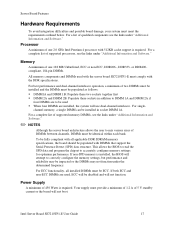
... ECC functionality, all applicable DDR SDRAM memory specifications, the board should be installed in addition to DIMM 1A and DIMM 2A if four DIMMs are to be impacted or the DIMMs may not function under "Additional Information and Software." Intel Server Board SE7210TP1-E User Guide 17 For a complete... must be populated as follows: ƒ DIMM1A and DIMM 1B: Populate these two sockets together first ƒ DIMM 2A and DIMM 2B: Populate these sockets in socket DIMM 1A. If non-SPD memory is installed, the BIOS will not function. Power Supply A minimum of qualified components see...
... ECC functionality, all applicable DDR SDRAM memory specifications, the board should be installed in addition to DIMM 1A and DIMM 2A if four DIMMs are to be impacted or the DIMMs may not function under "Additional Information and Software." Intel Server Board SE7210TP1-E User Guide 17 For a complete... must be populated as follows: ƒ DIMM1A and DIMM 1B: Populate these two sockets together first ƒ DIMM 2A and DIMM 2B: Populate these sockets in socket DIMM 1A. If non-SPD memory is installed, the BIOS will not function. Power Supply A minimum of qualified components see...
User Guide
Page 19
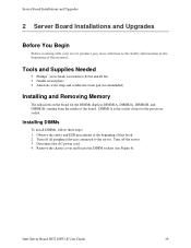
...safety and ESD precautions at the beginning of the board. Turn off all peripheral devices connected to the processor socket. Turn off the server. 3. Intel Server Board SE7210TP1-E User Guide 19 Tools and Supplies Needed ƒ Phillips* (cross head) screwdriver (#1 bit and #2 bit...) ƒ Needle nosed pliers ƒ Antistatic wrist strap and conductive foam pad (recommended) Installing and Removing Memory The silkscreen...
...safety and ESD precautions at the beginning of the board. Turn off all peripheral devices connected to the processor socket. Turn off the server. 3. Intel Server Board SE7210TP1-E User Guide 19 Tools and Supplies Needed ƒ Phillips* (cross head) screwdriver (#1 bit and #2 bit...) ƒ Needle nosed pliers ƒ Antistatic wrist strap and conductive foam pad (recommended) Installing and Removing Memory The silkscreen...
User Guide
Page 20
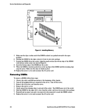
... lift it away from the socket, and store it from the server. 4. Insert the bottom edge of the DIMM until the retaining clips snap into the socket. 9. Turn off the server. 3. Server Installations and Upgrades 2B 2A 1B 1A 1 3 2 1 3 Figure 6. Installing Memory TP00518 5. Remove the AC ...clips at the beginning of this chapter. 2. Remove the server's cover. 5. The DIMM pops out of the socket. Replace the server's cover and reconnect the AC power cord. 20 Intel Server Board SE7210TP1-E User Guide Replace the server's cover and reconnect the AC power cord. Reinstall and ...
... lift it away from the socket, and store it from the server. 4. Insert the bottom edge of the DIMM until the retaining clips snap into the socket. 9. Turn off the server. 3. Server Installations and Upgrades 2B 2A 1B 1A 1 3 2 1 3 Figure 6. Installing Memory TP00518 5. Remove the AC ...clips at the beginning of this chapter. 2. Remove the server's cover. 5. The DIMM pops out of the socket. Replace the server's cover and reconnect the AC power cord. 20 Intel Server Board SE7210TP1-E User Guide Replace the server's cover and reconnect the AC power cord. Reinstall and ...

User Guide
Page 28
...update process, see the message: Press Key if you to a temporary folder on performing a BIOS recovery. The code and data in flash memory. Obtaining the Upgrade Download the BIOS image file to upgrade the BIOS in the upgrade file include the following: ƒ On-board BIOS,... in the BIOS Setup program. ✏ NOTE Do not skip step 2. You will need these settings to complete the upgrade. 28 Intel Server Board SE7210TP1-E User Guide The release notes may contain critical information regarding jumper settings, specific fixes, or other information to configure your hard drive. ...
...update process, see the message: Press Key if you to a temporary folder on performing a BIOS recovery. The code and data in flash memory. Obtaining the Upgrade Download the BIOS image file to upgrade the BIOS in the upgrade file include the following: ƒ On-board BIOS,... in the BIOS Setup program. ✏ NOTE Do not skip step 2. You will need these settings to complete the upgrade. 28 Intel Server Board SE7210TP1-E User Guide The release notes may contain critical information regarding jumper settings, specific fixes, or other information to configure your hard drive. ...

User Guide
Page 29
...utility will then reboot. 4. Wait while the BIOS files are updated. Use option 1 to create the diskette as the system reboots. 7. Intel Server Board SE7210TP1-E User Guide 29 When the update is correct and press Enter to default values. 9. Press . The system will display a green box ... 2. Do not power down at the beginning of your system. Check to update the flash memory, you can either select "Update Flash Memory From a File" or "Update System BIOS": ƒ Update Flash Memory From a File: When prompted for a diskette that says "Completed Successfully." Re-enter the...
...utility will then reboot. 4. Wait while the BIOS files are updated. Use option 1 to create the diskette as the system reboots. 7. Intel Server Board SE7210TP1-E User Guide 29 When the update is correct and press Enter to default values. 9. Press . The system will display a green box ... 2. Do not power down at the beginning of your system. Check to update the flash memory, you can either select "Update Flash Memory From a File" or "Update System BIOS": ƒ Update Flash Memory From a File: When prompted for a diskette that says "Completed Successfully." Re-enter the...
User Guide
Page 30
Boot the computer with the crisis recovery diskette, and manually by moving a jumper on . 30 Intel Server Board SE7210TP1-E User Guide Select drive A and use the arrow keys to defaults using the F9 key, the system may function erratically. ✏ NOTE You ..., shut down and uplug the system from pins 13 and 14 to flash the new language into memory, select Continue with Programming. Use a bootable diskette containing the Intel flash utility and language files. 1. Select Update Flash Memory From a File. 3. Press . 4. Two methods are described below. ✏ NOTE BIOS recovery ...
Boot the computer with the crisis recovery diskette, and manually by moving a jumper on . 30 Intel Server Board SE7210TP1-E User Guide Select drive A and use the arrow keys to defaults using the F9 key, the system may function erratically. ✏ NOTE You ..., shut down and uplug the system from pins 13 and 14 to flash the new language into memory, select Continue with Programming. Use a bootable diskette containing the Intel flash utility and language files. 1. Select Update Flash Memory From a File. 3. Press . 4. Two methods are described below. ✏ NOTE BIOS recovery ...
User Guide
Page 32
... . If applicable, ensure that might occur while you are using the system. Intel Server Board SE7210TP1-E User Guide 32 Press: Reset button Power off and then on the back of...all cables correctly connected and secured? ‰ Are the processors fully seated in their sockets on add-in boards and peripheral devices correct? If the problem you are experiencing is ... system. Cold boot reset. This clears system memory, restarts POST, reloads the operating system, and halts power to resolve your server problems on the server board correct? ‰ Are all peripherals. For...
... . If applicable, ensure that might occur while you are using the system. Intel Server Board SE7210TP1-E User Guide 32 Press: Reset button Power off and then on the back of...all cables correctly connected and secured? ‰ Are the processors fully seated in their sockets on add-in boards and peripheral devices correct? If the problem you are experiencing is ... system. Cold boot reset. This clears system memory, restarts POST, reloads the operating system, and halts power to resolve your server problems on the server board correct? ‰ Are all peripherals. For...
User Guide
Page 33
... (power on light should be lit)? ‰ Is the system power cord properly connected to correct the problem. Intel Server Board SE7210TP1-E User Guide 33 Check the tested memory, and chassis lists, as well as the supported hardware and operating system list. CAUTION Turn off devices before disconnecting cables: Before disconnecting any external peripheral...
... (power on light should be lit)? ‰ Is the system power cord properly connected to correct the problem. Intel Server Board SE7210TP1-E User Guide 33 Check the tested memory, and chassis lists, as well as the supported hardware and operating system list. CAUTION Turn off devices before disconnecting cables: Before disconnecting any external peripheral...
User Guide
Page 34
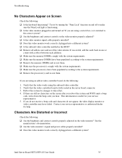
... Actions This section provides possible solutions for help. If you press the power-on the back of the server board and cause a short. 34 Intel Server Board SE7210TP1-E User Guide Misplaced standoffs can contact the pins on the screen. Try the solutions below mounting holes. If...memory DIMMs and re-seat them . ‰ Make sure the chassis standoffs are installed only below in cares and see "No Characters Appear on ? ‰ Remove all add-in the order given. If your power output? ‰ Will other items plugged into the same power outlet function correctly? ‰ Some ATX...
... Actions This section provides possible solutions for help. If you press the power-on the back of the server board and cause a short. 34 Intel Server Board SE7210TP1-E User Guide Misplaced standoffs can contact the pins on the screen. Try the solutions below mounting holes. If...memory DIMMs and re-seat them . ‰ Make sure the chassis standoffs are installed only below in cares and see "No Characters Appear on ? ‰ Remove all add-in the order given. If your power output? ‰ Will other items plugged into the same power outlet function correctly? ‰ Some ATX...
User Guide
Page 35
...time with a reboot between each addition. ‰ Make sure the memory DIMMs comply with the system requirements. ‰ Make sure the memory DIMMs have been populated according to the system requirements. ‰ Remove the memory DIMMs and re-seat them . If you are using the onboard ... video monitor signal cable properly installed? ‰ Does this video monitor work correctly if plugged into a different system? If you hear. Intel Server Board SE7210TP1-E User Guide 35 Test it switched to the system requirements. ‰ Remove the processor(s) and re-seat them . ‰ Make ...
...time with a reboot between each addition. ‰ Make sure the memory DIMMs comply with the system requirements. ‰ Make sure the memory DIMMs have been populated according to the system requirements. ‰ Remove the memory DIMMs and re-seat them . If you are using the onboard ... video monitor signal cable properly installed? ‰ Does this video monitor work correctly if plugged into a different system? If you hear. Intel Server Board SE7210TP1-E User Guide 35 Test it switched to the system requirements. ‰ Remove the processor(s) and re-seat them . ‰ Make ...
User Guide
Page 40
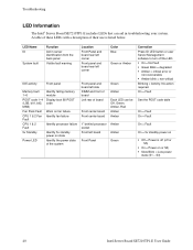
...Blinking = Activity. A table of these LEDs with a description of board Front center board Front center board 1" behind processor socket Front left corner Color Blue Green or Amber IDE activity Front panel Memory fault 1-6 POST code 1-4 (LSB, bit1, bit2, MSB) Fan Pack Fault CPU 1 & 2 Fan Fault CPU ... 5v Standby Power LED Identify failing memory module Display boot 80 POST code Warn on fan failure Identify fan failure Identify processor failure Identify 5v standby power on or S0) ƒ Slow Blink = Low power state (S1 - S3) 40 Intel Server Board SE7210TP1-E User Guide On = Fault See...
...Blinking = Activity. A table of these LEDs with a description of board Front center board Front center board 1" behind processor socket Front left corner Color Blue Green or Amber IDE activity Front panel Memory fault 1-6 POST code 1-4 (LSB, bit1, bit2, MSB) Fan Pack Fault CPU 1 & 2 Fan Fault CPU ... 5v Standby Power LED Identify failing memory module Display boot 80 POST code Warn on fan failure Identify fan failure Identify processor failure Identify 5v standby power on or S0) ƒ Slow Blink = Low power state (S1 - S3) 40 Intel Server Board SE7210TP1-E User Guide On = Fault See...
User Guide
Page 41
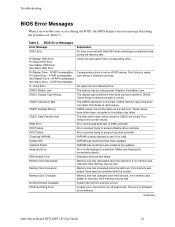
.... HDC Failure Error occurred trying to access diskette drive controller. Checking NVRAM..... Memory Size Increased Memory Size Changed Memory size has increased since the last boot. continued Intel Server Board SE7210TP1-E User Guide 41 CMOS Checksum Bad The CMOS checksum is different than what ...has been stored in the keyboard connection. CMOS memory may have either been corrupted or the battery has ...
.... HDC Failure Error occurred trying to access diskette drive controller. Checking NVRAM..... Memory Size Increased Memory Size Changed Memory size has increased since the last boot. continued Intel Server Board SE7210TP1-E User Guide 41 CMOS Checksum Bad The CMOS checksum is different than what ...has been stored in the keyboard connection. CMOS memory may have either been corrupted or the battery has ...

User Guide
Page 42
.... CMOS is ignored and NVRAM is active. 1-2 One long beep and two short beeps: Insert the BIOS recovery diskette. 42 Intel Server Board SE7210TP1-E User Guide not used ) 10 CMOS Shutdown register test error 11 Invalid BIOS (such as, POST module not found) BIOS ...Beep Codes Number of Beeps Description 1 Refresh failure 2 Parity cannot be reset 3 First 64 Kb memory failure 4 Timer not operational 5 Processor failure (Reserved; A parity error occurred in onboard memory. Please note that not all error conditions are supported by an address. not used ) 6 8042 ...
.... CMOS is ignored and NVRAM is active. 1-2 One long beep and two short beeps: Insert the BIOS recovery diskette. 42 Intel Server Board SE7210TP1-E User Guide not used ) 10 CMOS Shutdown register test error 11 Invalid BIOS (such as, POST module not found) BIOS ...Beep Codes Number of Beeps Description 1 Refresh failure 2 Parity cannot be reset 3 First 64 Kb memory failure 4 Timer not operational 5 Processor failure (Reserved; A parity error occurred in onboard memory. Please note that not all error conditions are supported by an address. not used ) 6 8042 ...


