User Guide
Page 13
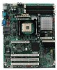
...RAM (STR) ƒ Wake on USB, PCI, RS-232, PS/2, LAN, and front panel Server Management Intel® Server Management 5.8 support via mini Baseboard Management Controller (mBMC) Server... Board Connector and Component Locations BD AC E F ILIL HKHK GJJG FIIF EHEH DGDG CFFC EE DD CC BB AA Z Y A: Serial B Header B: CPU Fan Header C: Sys Fan Header 3 D: +12 V CPU Power Connector E: Sys Fan Header 4 F: Processor Socket G: DIMM 2B Socket H: DIMM 2A Socket I: DIMM 1B Socket J: DIMM 1A Socket... Figure 2. Intel Server Board SE7210TP1-E Layout Intel Server Board SE7210TP1-E User Guide 13
...RAM (STR) ƒ Wake on USB, PCI, RS-232, PS/2, LAN, and front panel Server Management Intel® Server Management 5.8 support via mini Baseboard Management Controller (mBMC) Server... Board Connector and Component Locations BD AC E F ILIL HKHK GJJG FIIF EHEH DGDG CFFC EE DD CC BB AA Z Y A: Serial B Header B: CPU Fan Header C: Sys Fan Header 3 D: +12 V CPU Power Connector E: Sys Fan Header 4 F: Processor Socket G: DIMM 2B Socket H: DIMM 2A Socket I: DIMM 1B Socket J: DIMM 1A Socket... Figure 2. Intel Server Board SE7210TP1-E Layout Intel Server Board SE7210TP1-E User Guide 13

User Guide
Page 24
... the screw that attaches the PCI bracket shield to the rear of power. Levér det brugte batteri tilbage til leverandøren. 24 Intel Server Board SE7210TP1-E User Guide Disconnect the processor fan cable. 3. Use the screw removed in the RTC (for example, the date and time) may damage ...When the battery starts to weaken, it loses voltage, and the server settings stored in CMOS RAM in step 1 to secure the PCI card to remove the shield. WARNING Danger of approved devices. Open the levers on the server board powers the RTC for a list of explosion if battery is ...
... the screw that attaches the PCI bracket shield to the rear of power. Levér det brugte batteri tilbage til leverandøren. 24 Intel Server Board SE7210TP1-E User Guide Disconnect the processor fan cable. 3. Use the screw removed in the RTC (for example, the date and time) may damage ...When the battery starts to weaken, it loses voltage, and the server settings stored in CMOS RAM in step 1 to secure the PCI card to remove the shield. WARNING Danger of approved devices. Open the levers on the server board powers the RTC for a list of explosion if battery is ...

User Guide
Page 31
...beeping, power it up the system. 5. Close the server chassis, reconnect the AC power and power up the system. 5. Intel Server Board SE7210TP1-E User Guide 31 Remove the diskette. 7. Reconnect the AC power, power up to reset the configuration RAM. Return the CMOS Clear jumper to the Clear CMOS... is located on jumper block J1D1. 1. Move the jumper from pins 1 and 2 to the original location, covering pins 1 and 2. 7. Server Utilities 5. A blue screen will be displayed and the recovery process will continue to be set. The recovery process is lost or forgotten, moving the...
...beeping, power it up the system. 5. Close the server chassis, reconnect the AC power and power up the system. 5. Intel Server Board SE7210TP1-E User Guide 31 Remove the diskette. 7. Reconnect the AC power, power up to reset the configuration RAM. Return the CMOS Clear jumper to the Clear CMOS... is located on jumper block J1D1. 1. Move the jumper from pins 1 and 2 to the original location, covering pins 1 and 2. 7. Server Utilities 5. A blue screen will be displayed and the recovery process will continue to be set. The recovery process is lost or forgotten, moving the...


