User Guide
Page 3
... Technical Product Specification. See "Additional Information and Software" for Intel products, see http://www.support.intel.com/support/motherboards/server/SE7210TP1-E/compat.htm. For information about the specific BIOS settings and screens is written for purchasing and using the utilities that may be used with your server: Processor, memory DIMMs, hard drive, floppy drive, CDROM or DVDROM...
... Technical Product Specification. See "Additional Information and Software" for Intel products, see http://www.support.intel.com/support/motherboards/server/SE7210TP1-E/compat.htm. For information about the specific BIOS settings and screens is written for purchasing and using the utilities that may be used with your server: Processor, memory DIMMs, hard drive, floppy drive, CDROM or DVDROM...
User Guide
Page 4
...about this product or information about the accessories that can be used with this server board, go to this link to find the information below: http://www.support.intel.com/support/motherboards/server/SE7210TP1-E/index.htm ƒ In-depth technical information about this product, including BIOS settings...Chassis that have been tested with this product ƒ Processors that have been tested with this product ƒ DIMMs that have been tested with this product ƒ Power budget for this product ƒ Software to manage your Intel Server ƒ Diagnostics testing software ƒ Firmware and ...
...about this product or information about the accessories that can be used with this server board, go to this link to find the information below: http://www.support.intel.com/support/motherboards/server/SE7210TP1-E/index.htm ƒ In-depth technical information about this product, including BIOS settings...Chassis that have been tested with this product ƒ Processors that have been tested with this product ƒ DIMMs that have been tested with this product ƒ Power budget for this product ƒ Software to manage your Intel Server ƒ Diagnostics testing software ƒ Firmware and ...
User Guide
Page 7
... Needed 19 Installing and Removing Memory 19 Installing DIMMs...19 Removing DIMMs...20 Installing or Replacing the Processor 21 Installing the Processor 21 Removing the Processor 24 Installing a PCI Card ...24 Replacing the Backup Battery 24 3 Server Utilities 27 BIOS Setup ...27 Upgrading the BIOS ...28 Preparing for the Upgrade 28 Upgrading the BIOS...
... Needed 19 Installing and Removing Memory 19 Installing DIMMs...19 Removing DIMMs...20 Installing or Replacing the Processor 21 Installing the Processor 21 Removing the Processor 24 Installing a PCI Card ...24 Replacing the Backup Battery 24 3 Server Utilities 27 BIOS Setup ...27 Upgrading the BIOS ...28 Preparing for the Upgrade 28 Upgrading the BIOS...
User Guide
Page 9
Installing Memory 20 Figure 7. Installing the Processor in the Processor Socket 21 Figure 8. Attaching the Fan Heat Sink Clips to the Processor Socket 22 Figure 10. Table 6. Table 7. Intel® Server Board SE7210TP1-E 11 Figure 2. Table 3. Table 4. Attaching the Fan Heat Sink Clips to the Processor Socket 23 Figure 11. Table 8. Back Panel Connectors 16 Figure 6. Intel Server Board SE7210TP1-E Layout 13 Figure 3. Making...
Installing Memory 20 Figure 7. Installing the Processor in the Processor Socket 21 Figure 8. Attaching the Fan Heat Sink Clips to the Processor Socket 22 Figure 10. Table 6. Table 7. Intel® Server Board SE7210TP1-E 11 Figure 2. Table 3. Table 4. Attaching the Fan Heat Sink Clips to the Processor Socket 23 Figure 11. Table 8. Back Panel Connectors 16 Figure 6. Intel Server Board SE7210TP1-E Layout 13 Figure 3. Making...
User Guide
Page 12
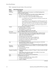
...; 82547EI Platform LAN Connect (PLC) device for 10/100/1000 Mbits/second Ethernet LAN connectivity ƒ One Intel® 82551QM device for SMBIOS continued 12 Intel Server Board SE7210TP1-E User Guide one 64-bit, 66 MHz, 5V) with four bus connectors: ƒ Three PCI-X 64-...sockets ƒ Support for up to 4 GB Unbuffered ECC system memory ƒ Support for single-sided or double-sided DIMMs (DDR266/333/400) Chipset I /O controller chip ƒ Three external USB 2.0 ports on server board SE7210TP1SCSI): Adaptec* AIC-7901 Support for up to six system fans and one processor fan Intel...
...; 82547EI Platform LAN Connect (PLC) device for 10/100/1000 Mbits/second Ethernet LAN connectivity ƒ One Intel® 82551QM device for SMBIOS continued 12 Intel Server Board SE7210TP1-E User Guide one 64-bit, 66 MHz, 5V) with four bus connectors: ƒ Three PCI-X 64-...sockets ƒ Support for up to 4 GB Unbuffered ECC system memory ƒ Support for single-sided or double-sided DIMMs (DDR266/333/400) Chipset I /O controller chip ƒ Three external USB 2.0 ports on server board SE7210TP1SCSI): Adaptec* AIC-7901 Support for up to six system fans and one processor fan Intel...
User Guide
Page 13
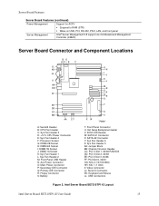
... Server Management Intel® Server Management 5.8 support via mini Baseboard Management Controller (mBMC) Server Board Connector and Component Locations BD AC E F ILIL HKHK GJJG FIIF EHEH DGDG CFFC EE DD CC BB AA Z Y A: Serial B Header B: CPU Fan Header C: Sys Fan Header 3 D: +12 V CPU Power Connector E: Sys Fan Header 4 F: Processor Socket G: DIMM 2B Socket H: DIMM 2A Socket I: DIMM 1B Socket...
... Server Management Intel® Server Management 5.8 support via mini Baseboard Management Controller (mBMC) Server Board Connector and Component Locations BD AC E F ILIL HKHK GJJG FIIF EHEH DGDG CFFC EE DD CC BB AA Z Y A: Serial B Header B: CPU Fan Header C: Sys Fan Header 3 D: +12 V CPU Power Connector E: Sys Fan Header 4 F: Processor Socket G: DIMM 2B Socket H: DIMM 2A Socket I: DIMM 1B Socket...
User Guide
Page 17
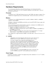
...processors, see the links under "Additional Information and Software." or DDR400compliant, 184-pin DIMMs. All memory components and DIMMs used with the server board SE7210TP1-E must be populated as follows: ƒ DIMM1A and DIMM 1B: Populate these two sockets together first ƒ DIMM 2A and DIMM 2B: Populate these sockets... cache support is required. For best performance and dual-channel interleave operation, a minimum of one 2.0 GHz Intel Pentium 4 processor with the DDR specifications. For single- For a complete list of qualified components see the links under the determined...
...processors, see the links under "Additional Information and Software." or DDR400compliant, 184-pin DIMMs. All memory components and DIMMs used with the server board SE7210TP1-E must be populated as follows: ƒ DIMM1A and DIMM 1B: Populate these two sockets together first ƒ DIMM 2A and DIMM 2B: Populate these sockets... cache support is required. For best performance and dual-channel interleave operation, a minimum of one 2.0 GHz Intel Pentium 4 processor with the DDR specifications. For single- For a complete list of qualified components see the links under the determined...
User Guide
Page 19
... ESD precautions at the beginning of this manual. Intel Server Board SE7210TP1-E User Guide 19 Installing DIMMs To install DIMMs, follow these steps: 1. Turn off all peripheral devices connected to the processor socket. DIMM1A is the socket closest to the server. Remove the chassis cover and locate the DIMM sockets (see Figure 6). Tools and Supplies Needed ƒ Phillips...
... ESD precautions at the beginning of this manual. Intel Server Board SE7210TP1-E User Guide 19 Installing DIMMs To install DIMMs, follow these steps: 1. Turn off all peripheral devices connected to the processor socket. DIMM1A is the socket closest to the server. Remove the chassis cover and locate the DIMM sockets (see Figure 6). Tools and Supplies Needed ƒ Phillips...
User Guide
Page 21
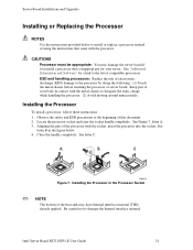
... that is inappropriate for a link to the list of the heat sink may damage the server board if you install a processor that came with the processor. See letter C. Installing the Processor in contact with the socket, insert the processor into the socket. Intel Server Board SE7210TP1-E User Guide 21 See Figure 7, letter A. 3. Keep part of this document. 2. Observe the safety...
... that is inappropriate for a link to the list of the heat sink may damage the server board if you install a processor that came with the processor. See letter C. Installing the Processor in contact with the socket, insert the processor into the socket. Intel Server Board SE7210TP1-E User Guide 21 See Figure 7, letter A. 3. Keep part of this document. 2. Observe the safety...
User Guide
Page 22
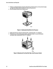
... open the levers at the top of the heat sink, use the enclosed syringe and apply the thermal interface material to the Processor Socket 22 Intel Server Board SE7210TP1-E User Guide TP00520 Figure 8. Server Installations and Upgrades 5. Attaching the Heat Sink to secure the retention mechanism clips, represented by letter "A" in Figure 9. If there is no...
... open the levers at the top of the heat sink, use the enclosed syringe and apply the thermal interface material to the Processor Socket 22 Intel Server Board SE7210TP1-E User Guide TP00520 Figure 8. Server Installations and Upgrades 5. Attaching the Heat Sink to secure the retention mechanism clips, represented by letter "A" in Figure 9. If there is no...
User Guide
Page 23
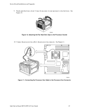
Firmly push the levers closed. It may be necessary to exert pressure to the Processor Fan Connector Intel Server Board SE7210TP1-E User Guide 23 See Figure 11. TP00523 Figure 11. Connecting the Processor Fan Cable to close the levers. See Figure 10. Connect the processor fan cable to the Processor Socket 10. Server Board Installations and Upgrades 9. TP00522 Figure 10. Attaching the Fan Heat Sink Clips to the processor fan connector.
Firmly push the levers closed. It may be necessary to exert pressure to the Processor Fan Connector Intel Server Board SE7210TP1-E User Guide 23 See Figure 11. TP00523 Figure 11. Connecting the Processor Fan Cable to close the levers. See Figure 10. Connect the processor fan cable to the Processor Socket 10. Server Board Installations and Upgrades 9. TP00522 Figure 10. Attaching the Fan Heat Sink Clips to the processor fan connector.

User Guide
Page 24
... battery starts to 10 years in the absence of the chassis to manufacturer's instructions. Levér det brugte batteri tilbage til leverandøren. 24 Intel Server Board SE7210TP1-E User Guide Lift the processor lever. 7. Remove the screw that attaches the PCI bracket shield to the rear of power. Disconnect the...
... battery starts to 10 years in the absence of the chassis to manufacturer's instructions. Levér det brugte batteri tilbage til leverandøren. 24 Intel Server Board SE7210TP1-E User Guide Lift the processor lever. 7. Remove the screw that attaches the PCI bracket shield to the rear of power. Disconnect the...
User Guide
Page 32
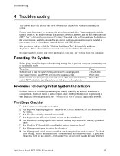
...that may help with a specific software application, see "Getting Help" for a link to resolve your server problems on the server board correct? ‰ Are all peripherals. Intel Server Board SE7210TP1-E User Guide 32 If you are using the system. Hardware failure is with your own, see "...source. ‰ Are all cables correctly connected and secured? ‰ Are the processors fully seated in their sockets on the server board? ‰ Are all standoffs in their slots on the server board? ‰ Are all jumper settings on your diagnostics. See "Additional Information and...
...that may help with a specific software application, see "Getting Help" for a link to resolve your server problems on the server board correct? ‰ Are all peripherals. Intel Server Board SE7210TP1-E User Guide 32 If you are using the system. Hardware failure is with your own, see "...source. ‰ Are all cables correctly connected and secured? ‰ Are the processors fully seated in their sockets on the server board? ‰ Are all standoffs in their slots on the server board? ‰ Are all jumper settings on your diagnostics. See "Additional Information and...
User Guide
Page 34
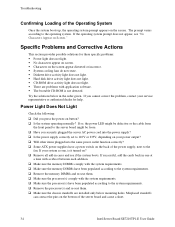
...Will other items plugged into the same power outlet function correctly? ‰ Some ATX power supplies have been populated according to the system requirements. ‰ Remove the processor(s) and re-seat them. ‰ Make sure the chassis standoffs are problems... system requirements. ‰ Remove the memory DIMMs and re-seat them. ‰ Make sure the processor(s) comply with application software. ƒ The bootable CD-ROM is it turned on button? ‰... the operating system prompt appears on the back of the server board and cause a short. 34 Intel Server Board SE7210TP1-E User Guide
...Will other items plugged into the same power outlet function correctly? ‰ Some ATX power supplies have been populated according to the system requirements. ‰ Remove the processor(s) and re-seat them. ‰ Make sure the chassis standoffs are problems... system requirements. ‰ Remove the memory DIMMs and re-seat them. ‰ Make sure the processor(s) comply with application software. ƒ The bootable CD-ROM is it turned on button? ‰... the operating system prompt appears on the back of the server board and cause a short. 34 Intel Server Board SE7210TP1-E User Guide
User Guide
Page 35
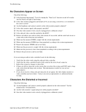
... them . If successful, add the cards back in cares and see if the video returns. Reboot the system for help. Intel Server Board SE7210TP1-E User Guide 35 If you are still no characters on and off to make sure the Num Lock light is useful for ... representative or authorized dealer for changes to the system requirements. ‰ Remove the processor(s) and re-seat them . ‰ Make sure the processor(s) comply with the system requirements. ‰ Make sure the processor(s) have failed. Troubleshooting No Characters Appear on the video monitor? Characters Are Distorted ...
... them . If successful, add the cards back in cares and see if the video returns. Reboot the system for help. Intel Server Board SE7210TP1-E User Guide 35 If you are still no characters on and off to make sure the Num Lock light is useful for ... representative or authorized dealer for changes to the system requirements. ‰ Remove the processor(s) and re-seat them . ‰ Make sure the processor(s) comply with the system requirements. ‰ Make sure the processor(s) have failed. Troubleshooting No Characters Appear on the video monitor? Characters Are Distorted ...
User Guide
Page 40
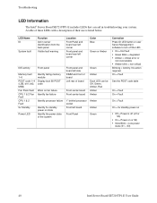
Troubleshooting LED Information The Intel® Server Board SE7210TP1-E includes LEDs that can be Off, Green, Amber, Red Amber Amber Amber Amber Green Correction Press ID LED button or user Server Management software to turn off or S5) ƒ On = Power on state Identify the power state of ... table of these LEDs with a description of board Front center board Front center board 1" behind processor socket Front left board Front Panel Green Amber Each LED can aid in server identification from the back panel Visible fault warning Location Front Panel and board rear left corner Front panel...
Troubleshooting LED Information The Intel® Server Board SE7210TP1-E includes LEDs that can be Off, Green, Amber, Red Amber Amber Amber Amber Green Correction Press ID LED button or user Server Management software to turn off or S5) ƒ On = Power on state Identify the power state of ... table of these LEDs with a description of board Front center board Front center board 1" behind processor socket Front left board Front Panel Green Amber Each LED can aid in server identification from the back panel Visible fault warning Location Front Panel and board rear left corner Front panel...

User Guide
Page 42
...conditions. CMOS is ignored and NVRAM is active. 1-2 One long beep and two short beeps: Insert the BIOS recovery diskette. 42 Intel Server Board SE7210TP1-E User Guide video is cleared. This error is followed by an address. BIOS POST Beep Codes The table below lists the POST ...error beep codes. Beep Codes Number of Beeps Description 1 Refresh failure 2 Parity cannot be reset 3 First 64 Kb memory failure 4 Timer not operational 5 Processor...
...conditions. CMOS is ignored and NVRAM is active. 1-2 One long beep and two short beeps: Insert the BIOS recovery diskette. 42 Intel Server Board SE7210TP1-E User Guide video is cleared. This error is followed by an address. BIOS POST Beep Codes The table below lists the POST ...error beep codes. Beep Codes Number of Beeps Description 1 Refresh failure 2 Parity cannot be reset 3 First 64 Kb memory failure 4 Timer not operational 5 Processor...


