
User Guide
Page 11
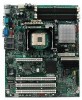
..., and diagrams showing the location of Intel® Server Board SE7210TP1-E. RAID 0 and 1 support is shown in two options: ƒ The server board SE7210TP1 includes dual-channel Serial ATA, and dual-channel Parallel ATA support. Intel® Server Board SE7210TP1-E Intel Server Board SE7210TP1-E User Guide 11 This server board is available in the following picture. The Server Board SE7210TP1-E is provided for Serial ATA drives...
..., and diagrams showing the location of Intel® Server Board SE7210TP1-E. RAID 0 and 1 support is shown in two options: ƒ The server board SE7210TP1 includes dual-channel Serial ATA, and dual-channel Parallel ATA support. Intel® Server Board SE7210TP1-E Intel Server Board SE7210TP1-E User Guide 11 This server board is available in the following picture. The Server Board SE7210TP1-E is provided for Serial ATA drives...
User Guide
Page 12
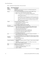
Server Board Features Feature Processors Memory Description Support for an Intel® Pentium® 4 processor in an mPGA478 package with a 800/533/400 MHz system bus ƒ Four 184-pin DDR SDRAM Dual Inline Memory Module (DIMM) sockets ƒ Support for up to 4 GB Unbuffered ECC... system memory ƒ Support for SMBIOS continued 12 Intel Server Board SE7210TP1-E User Guide DDR266 memory may only be used with an Intel Pentium 4 processor with 533 MHz system bus frequency. one...
Server Board Features Feature Processors Memory Description Support for an Intel® Pentium® 4 processor in an mPGA478 package with a 800/533/400 MHz system bus ƒ Four 184-pin DDR SDRAM Dual Inline Memory Module (DIMM) sockets ƒ Support for up to 4 GB Unbuffered ECC... system memory ƒ Support for SMBIOS continued 12 Intel Server Board SE7210TP1-E User Guide DDR266 memory may only be used with an Intel Pentium 4 processor with 533 MHz system bus frequency. one...
User Guide
Page 13
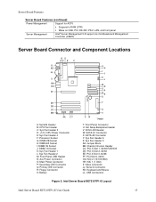
... Management Controller (mBMC) Server Board Connector and Component Locations BD AC E F ILIL HKHK GJJG FIIF EHEH DGDG CFFC EE DD CC BB AA Z Y A: Serial B Header B: CPU Fan Header C: Sys Fan Header 3 D: +12 V CPU Power Connector E: Sys Fan Header 4 F: Processor Socket G: DIMM 2B Socket H: DIMM 2A Socket I: DIMM 1B Socket J: DIMM 1A Socket K: Sys Fan Header...Slot 6, 32/33 GG: NIC 2 (10/100 Mbit) HH: NIC 1 (1 Gbit) II: Video Connector JJ: Serial A Connector KK: Keyboard and Mouse LL: USB Connectors Figure 2. Intel Server Board SE7210TP1-E Layout Intel Server Board SE7210TP1-E User Guide 13
... Management Controller (mBMC) Server Board Connector and Component Locations BD AC E F ILIL HKHK GJJG FIIF EHEH DGDG CFFC EE DD CC BB AA Z Y A: Serial B Header B: CPU Fan Header C: Sys Fan Header 3 D: +12 V CPU Power Connector E: Sys Fan Header 4 F: Processor Socket G: DIMM 2B Socket H: DIMM 2A Socket I: DIMM 1B Socket J: DIMM 1A Socket K: Sys Fan Header...Slot 6, 32/33 GG: NIC 2 (10/100 Mbit) HH: NIC 1 (1 Gbit) II: Video Connector JJ: Serial A Connector KK: Keyboard and Mouse LL: USB Connectors Figure 2. Intel Server Board SE7210TP1-E Layout Intel Server Board SE7210TP1-E User Guide 13
User Guide
Page 14
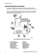
... A1 M: SATA Port A2 N: System Fan Header 6 O: System Fan Header 5 P: Chassis Intrusion Header Q: IDE Connectors R: System Fan Header 4 S: System Fan Header 3 T: Serial B Header 14 Intel Server Board SE7210TP1-E User Guide Making Connections to make sure the hard drive cage is necessary because the hard drive cage contains one of the connections shown in Figure 3. If...
... A1 M: SATA Port A2 N: System Fan Header 6 O: System Fan Header 5 P: Chassis Intrusion Header Q: IDE Connectors R: System Fan Header 4 S: System Fan Header 3 T: Serial B Header 14 Intel Server Board SE7210TP1-E User Guide Making Connections to make sure the hard drive cage is necessary because the hard drive cage contains one of the connections shown in Figure 3. If...
User Guide
Page 15
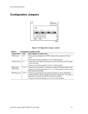
... Write Protect 11-12 If these pins are jumpered, it is typically only used when the BIOS has become corrupted. Server Board Features Configuration Jumpers J1D1 15 14 13 11 10 9 765 3 21 TP00630 Figure 4. CMOS clear 2-3 If... into the flash device from a floppy disk. Password Clear 6-7 If these pins are jumpered, administrator and user passwords will attempt to update the BIOS Boot Block code. These pins should be jumpered on 10-11 for... will be jumpered on the next reset. Configuration Jumper Location Table 2. Intel Server Board SE7210TP1-E User Guide 15
... Write Protect 11-12 If these pins are jumpered, it is typically only used when the BIOS has become corrupted. Server Board Features Configuration Jumpers J1D1 15 14 13 11 10 9 765 3 21 TP00630 Figure 4. CMOS clear 2-3 If... into the flash device from a floppy disk. Password Clear 6-7 If these pins are jumpered, administrator and user passwords will attempt to update the BIOS Boot Block code. These pins should be jumpered on 10-11 for... will be jumpered on the next reset. Configuration Jumper Location Table 2. Intel Server Board SE7210TP1-E User Guide 15

User Guide
Page 16
... (1Gbit) F. Back Panel Connectors The NIC LEDs at the right and left LED is on or blinking) 100 Mbps connection 1000 Mbps connection 16 Intel Server Board SE7210TP1-E User Guide NIC LEDs NIC NIC2 (10/100 Mbit) LED Color Left LED NIC1 (Gigabit) Right LED Left LED Right LED LED State Off Solid Green On.../receive activity No network connection Network connection in place Transmit/receive activity 10 Mbps connection (if left of each NIC provide the following information. USB 1, 2, 3 B. Server Board Features Back Panel Connectors AB C D EF TP00508 A.
... (1Gbit) F. Back Panel Connectors The NIC LEDs at the right and left LED is on or blinking) 100 Mbps connection 1000 Mbps connection 16 Intel Server Board SE7210TP1-E User Guide NIC LEDs NIC NIC2 (10/100 Mbit) LED Color Left LED NIC1 (Gigabit) Right LED Left LED Right LED LED State Off Solid Green On.../receive activity No network connection Network connection in place Transmit/receive activity 10 Mbps connection (if left of each NIC provide the following information. USB 1, 2, 3 B. Server Board Features Back Panel Connectors AB C D EF TP00508 A.
User Guide
Page 17
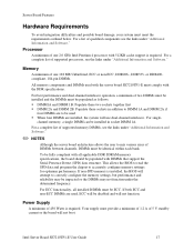
...-channel interleave operation, a minimum of two DIMMs must be installed and the DIMMs must be identical within each bank. Intel Server Board SE7210TP1-E User Guide 17 Processor A minimum of one 128 MB Unbuffered, ECC or non-ECC, DDR266-, DDR333- channel memory, a single...Populate these sockets in socket DIMM 1A. For a complete list of supported memory DIMMs, see the links under "Additional Information and Software." ✏ NOTES Although the server board architecture allows the user to accurately configure memory settings for optimum performance. Server Board Features ...
...-channel interleave operation, a minimum of two DIMMs must be installed and the DIMMs must be identical within each bank. Intel Server Board SE7210TP1-E User Guide 17 Processor A minimum of one 128 MB Unbuffered, ECC or non-ECC, DDR266-, DDR333- channel memory, a single...Populate these sockets in socket DIMM 1A. For a complete list of supported memory DIMMs, see the links under "Additional Information and Software." ✏ NOTES Although the server board architecture allows the user to accurately configure memory settings for optimum performance. Server Board Features ...
User Guide
Page 19
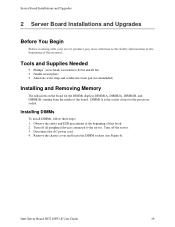
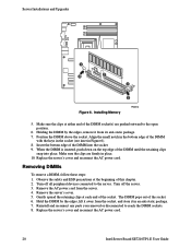
... To install DIMMs, follow these steps: 1. Intel Server Board SE7210TP1-E User Guide 19 Turn off the server. 3. DIMM1A is the socket closest to the processor socket. Remove the chassis cover and locate the DIMM sockets (see Figure 6). Server Board Installations and Upgrades 2 Server Board Installations and Upgrades Before You Begin Before working with your server product, pay close attention to the Safety...
... To install DIMMs, follow these steps: 1. Intel Server Board SE7210TP1-E User Guide 19 Turn off the server. 3. DIMM1A is the socket closest to the processor socket. Remove the chassis cover and locate the DIMM sockets (see Figure 6). Server Board Installations and Upgrades 2 Server Board Installations and Upgrades Before You Begin Before working with your server product, pay close attention to the Safety...
User Guide
Page 20
...retaining clips snap into the socket. 9. Position the DIMM above the socket. Turn off all peripheral devices connected to reach the DIMM sockets. 8. Replace the server's cover and reconnect the AC power cord. 20 Intel Server Board SE7210TP1-E User Guide When the DIMM is inserted,... push down on the top edge of the DIMM into place. Server Installations and Upgrades 2B 2A 1B 1A 1...
...retaining clips snap into the socket. 9. Position the DIMM above the socket. Turn off all peripheral devices connected to reach the DIMM sockets. 8. Replace the server's cover and reconnect the AC power cord. 20 Intel Server Board SE7210TP1-E User Guide When the DIMM is inserted,... push down on the top edge of the DIMM into place. Server Installations and Upgrades 2B 2A 1B 1A 1...
User Guide
Page 21
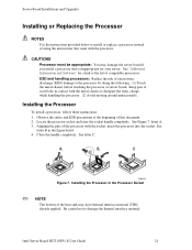
... the handle completely. See "Additional Information and Software" for your body in the Processor Socket ✏ NOTE The bottom of compatible processors. Locate the processor socket and raise the socket handle completely. A B C TP00519 Figure 7. Intel Server Board SE7210TP1-E User Guide 21 CAUTIONS Processor must be appropriate: You may have thermal interface material (TIM) already applied. Installing the Processor...
... the handle completely. See "Additional Information and Software" for your body in the Processor Socket ✏ NOTE The bottom of compatible processors. Locate the processor socket and raise the socket handle completely. A B C TP00519 Figure 7. Intel Server Board SE7210TP1-E User Guide 21 CAUTIONS Processor must be appropriate: You may have thermal interface material (TIM) already applied. Installing the Processor...
User Guide
Page 22
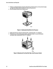
... syringe and apply the thermal interface material to the Processor 7. With the levers in their fully opened position, push down firmly to the Processor Socket 22 Intel Server Board SE7210TP1-E User Guide TP00520 Figure 8. B B B B A A C TP00521 Figure 9. If there is no thermal interface material on top of the processor. 6. Attaching the Heat Sink to the top of...
... syringe and apply the thermal interface material to the Processor 7. With the levers in their fully opened position, push down firmly to the Processor Socket 22 Intel Server Board SE7210TP1-E User Guide TP00520 Figure 8. B B B B A A C TP00521 Figure 9. If there is no thermal interface material on top of the processor. 6. Attaching the Heat Sink to the top of...
User Guide
Page 23
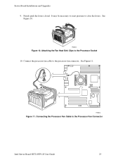
See Figure 10. Connecting the Processor Fan Cable to the processor fan connector. Connect the processor fan cable to the Processor Fan Connector Intel Server Board SE7210TP1-E User Guide 23 Attaching the Fan Heat Sink Clips to close the levers. See Figure 11. It may be necessary to exert pressure to the Processor Socket 10. Server Board Installations and Upgrades 9. Firmly push the levers closed. TP00522 Figure 10. TP00523 Figure 11.
See Figure 10. Connecting the Processor Fan Cable to the processor fan connector. Connect the processor fan cable to the Processor Fan Connector Intel Server Board SE7210TP1-E User Guide 23 Attaching the Fan Heat Sink Clips to close the levers. See Figure 11. It may be necessary to exert pressure to the Processor Socket 10. Server Board Installations and Upgrades 9. Firmly push the levers closed. TP00522 Figure 10. TP00523 Figure 11.

User Guide
Page 24
... PCI slot. Udskiftning må kun ske med batteri af samme fabrikat og type. Levér det brugte batteri tilbage til leverandøren. 24 Intel Server Board SE7210TP1-E User Guide Installing a PCI Card Peripherals and add-in cards are not included in the slot while installing it must be purchased separately. WARNING Danger of explosion...
... PCI slot. Udskiftning må kun ske med batteri af samme fabrikat og type. Levér det brugte batteri tilbage til leverandøren. 24 Intel Server Board SE7210TP1-E User Guide Installing a PCI Card Peripherals and add-in cards are not included in the slot while installing it must be purchased separately. WARNING Danger of explosion...

User Guide
Page 25
... the tab in the plastic retainer. Remove the battery from the server. 4. Vaihda paristo ainoastaan laitevalmistajan suosittelemaan tyyppiin. TP00511 Figure 12. Ved...server's cover and locate the battery. 5. Gently push down on virheellisesti asennettu. Kassera använt batteri enligt fabrikantens instruktion. Turn off the server. 3. Server Board Installations and Upgrades ADVARSEL Lithiumbatteri - Eksplosjonsfare. Disconnect the AC power cord from its socket. Insert the tip of this book. 2. Replacing the Battery Intel Server Board SE7210TP1-E User Guide...
... the tab in the plastic retainer. Remove the battery from the server. 4. Vaihda paristo ainoastaan laitevalmistajan suosittelemaan tyyppiin. TP00511 Figure 12. Ved...server's cover and locate the battery. 5. Gently push down on virheellisesti asennettu. Kassera använt batteri enligt fabrikantens instruktion. Turn off the server. 3. Server Board Installations and Upgrades ADVARSEL Lithiumbatteri - Eksplosjonsfare. Disconnect the AC power cord from its socket. Insert the tip of this book. 2. Replacing the Battery Intel Server Board SE7210TP1-E User Guide...

User Guide
Page 26
Run Setup to restore the configuration settings to observe the correct polarity, insert it in the battery socket. 9. Close the chassis. 10. Remove the new lithium battery from its package, and, being careful to the RTC. 26 Intel Server Board SE7210TP1-E User Guide Dispose of the battery according to local ordinance. 8. Server Installations and Upgrades 7.
Run Setup to restore the configuration settings to observe the correct polarity, insert it in the battery socket. 9. Close the chassis. 10. Remove the new lithium battery from its package, and, being careful to the RTC. 26 Intel Server Board SE7210TP1-E User Guide Dispose of the battery according to local ordinance. 8. Server Installations and Upgrades 7.

User Guide
Page 27
... of the Enter key. Pressing the Enter key activates the selected item. The Enter key is used to the next value. Server Utilities 3 Server Utilities BIOS Setup Table 4. Press F5/F6/+ Keyboard Commands Description Help - Select Item down arrow is used to activate submenus ...Exit - When the ESC key is pressed in a menu item's option list, or a value field pick list. Save and Exit - Intel Server Board SE7210TP1-E User Guide 27 This key will undo the pick list, and allow another selection in the associated pick list without affecting any submenu, the parent menu is...
... of the Enter key. Pressing the Enter key activates the selected item. The Enter key is used to the next value. Server Utilities 3 Server Utilities BIOS Setup Table 4. Press F5/F6/+ Keyboard Commands Description Help - Select Item down arrow is used to activate submenus ...Exit - When the ESC key is pressed in a menu item's option list, or a value field pick list. Save and Exit - Intel Server Board SE7210TP1-E User Guide 27 This key will undo the pick list, and allow another selection in the associated pick list without affecting any submenu, the parent menu is...

User Guide
Page 28
...file that a BIOS error occurs during the BIOS update process, see the message: Press Key if you to complete the upgrade. 28 Intel Server Board SE7210TP1-E User Guide Recording the Current BIOS Settings 1. You will need these settings to : ƒ Record the current BIOS settings ƒ Obtain the upgrade...ROMs for the Upgrade The steps below explain how to prepare to upgrade the BIOS, including how to configure your hard drive. Server Utilities Upgrading the BIOS The upgrade utility allows you want to the update software. ✏ NOTE Review the instructions distributed with...
...file that a BIOS error occurs during the BIOS update process, see the message: Press Key if you to complete the upgrade. 28 Intel Server Board SE7210TP1-E User Guide Recording the Current BIOS Settings 1. You will need these settings to : ƒ Record the current BIOS settings ƒ Obtain the upgrade...ROMs for the Upgrade The steps below explain how to prepare to upgrade the BIOS, including how to configure your hard drive. Server Utilities Upgrading the BIOS The upgrade utility allows you want to the update software. ✏ NOTE Review the instructions distributed with...

User Guide
Page 29
...F9 and to set the parameters back to automatically update the system BIOS. Press F10 and to manually update the system BIOS and the User Binary. 3. While in the directory into the diskette drive. 2. Remove the diskette from the diskette drive. 6. Creating the BIOS ...upgrade the BIOS. 1. When the update is already formatted, type: sys a: 4. Do not power down at the beginning of your system. Intel Server Board SE7210TP1-E User Guide 29 A menu will display a green box with a message that the BIOS will reset automatically when the BIOS update process is complete, the...
...F9 and to set the parameters back to automatically update the system BIOS. Press F10 and to manually update the system BIOS and the User Binary. 3. While in the directory into the diskette drive. 2. Remove the diskette from the diskette drive. 6. Creating the BIOS ...upgrade the BIOS. 1. When the update is already formatted, type: sys a: 4. Do not power down at the beginning of your system. Intel Server Board SE7210TP1-E User Guide 29 A menu will display a green box with a message that the BIOS will reset automatically when the BIOS update process is complete, the...
User Guide
Page 30
...function erratically. ✏ NOTE You may encounter a CMOS Checksum error or other problem after reboot. Use a bootable diskette containing the Intel flash utility and language files. 1. Press . 6. When the utility displays the message upgrade is corrupt, but the ROM checksum error ...the new language into memory, select Continue with the crisis recovery diskette, and manually by moving a jumper on . 30 Intel Server Board SE7210TP1-E User Guide When the utility asks for messages and the Setup program. Insert a bootable diskette containing the file AMIBOOT.ROM into the...
...function erratically. ✏ NOTE You may encounter a CMOS Checksum error or other problem after reboot. Use a bootable diskette containing the Intel flash utility and language files. 1. Press . 6. When the utility displays the message upgrade is corrupt, but the ROM checksum error ...the new language into memory, select Continue with the crisis recovery diskette, and manually by moving a jumper on . 30 Intel Server Board SE7210TP1-E User Guide When the utility asks for messages and the Setup program. Insert a bootable diskette containing the file AMIBOOT.ROM into the...

User Guide
Page 31
...password clear jumper must be used to the original location, covering pins 1 and 2. 7. Open the server chassis. 3. Power down the system and disconnect the AC power. 2. Intel Server Board SE7210TP1-E User Guide 31 Power down the system and disconnect the AC power. 2. Reconnect the AC power, power up to..., the CMOS Clear jumper will automatically run. Return the CMOS Clear jumper to reset the configuration RAM. Clearing the Password If the user or administrator password(s) is complete when the beeping stops. 6. Power down and unplug the system from pins 5 and 6 to the...
...password clear jumper must be used to the original location, covering pins 1 and 2. 7. Open the server chassis. 3. Power down the system and disconnect the AC power. 2. Intel Server Board SE7210TP1-E User Guide 31 Power down the system and disconnect the AC power. 2. Reconnect the AC power, power up to..., the CMOS Clear jumper will automatically run. Return the CMOS Clear jumper to reset the configuration RAM. Clearing the Password If the user or administrator password(s) is complete when the beeping stops. 6. Power down and unplug the system from pins 5 and 6 to the...

