Product Guide
Page 7
... to add and replace components on the Intel® Server System S7000FC4UR Product Guide. This document provides a brief overview of the features of the chassis, a list of the server board and chassis features, and product diagrams to perform these tasks. • Chapter 6 provides instructions for adding and replacing processors, memory, boards, and other components you for...
... to add and replace components on the Intel® Server System S7000FC4UR Product Guide. This document provides a brief overview of the features of the chassis, a list of the server board and chassis features, and product diagrams to perform these tasks. • Chapter 6 provides instructions for adding and replacing processors, memory, boards, and other components you for...

Product Guide
Page 8
... sure your Intel® server Use this Document or Software Intel® Server System S7000FC4UR Technical Product Specification Intel® Server System S7000FC4UR Quick Start User's Guide in the product box Spares and Configuration Guide Tested Hardware Operating Systems List Supported Processors Supported Memory Power Budget Platform Confidence Tests (PCT) Driver (for operating system drivers) Firmware Update Intel System Management Software viii Intel® Server System S7000FC4UR Product Guide...
... sure your Intel® server Use this Document or Software Intel® Server System S7000FC4UR Technical Product Specification Intel® Server System S7000FC4UR Quick Start User's Guide in the product box Spares and Configuration Guide Tested Hardware Operating Systems List Supported Processors Supported Memory Power Budget Platform Confidence Tests (PCT) Driver (for operating system drivers) Firmware Update Intel System Management Software viii Intel® Server System S7000FC4UR Product Guide...

Product Guide
Page 9
... Organization vii Additional Information and Software viii Chapter 1: System Description 1 System Features 2 System Front 4 Front Control Panel 5 System Rear 10 Processors 12 System Memory 12 Power Subsystem 14 Power Supply Modules 14 Power ...System Board Set 22 Main Board 23 Memory Board 28 I/O Riser Board (optional 30 SAS Riser Board (optional 31 Front Panel Board 32 SAS Backplane Board 33 Power Distribution Board 35 Server and Platform Management 35 Chapter 2: Starting Up and Shutting Down the Server 37 Powering Up the Server 37 Intel® Server System S7000FC4UR...
... Organization vii Additional Information and Software viii Chapter 1: System Description 1 System Features 2 System Front 4 Front Control Panel 5 System Rear 10 Processors 12 System Memory 12 Power Subsystem 14 Power Supply Modules 14 Power ...System Board Set 22 Main Board 23 Memory Board 28 I/O Riser Board (optional 30 SAS Riser Board (optional 31 Front Panel Board 32 SAS Backplane Board 33 Power Distribution Board 35 Server and Platform Management 35 Chapter 2: Starting Up and Shutting Down the Server 37 Powering Up the Server 37 Intel® Server System S7000FC4UR...

Product Guide
Page 11
... the Processors 110 Handling the Intel® Xeon® Processor MP 110 Installing and Removing a Processor Thermal Blank 111 Removing a Processor Thermal Blank 111 Installing a Processor Thermal Blank 112 Installing and Removing a Processor 113 Installing a Processor 113 Removing a Processor 115 Removing and Installing the Center Brace 116 Intel® Server System S7000FC4UR Product Guide xi
... the Processors 110 Handling the Intel® Xeon® Processor MP 110 Installing and Removing a Processor Thermal Blank 111 Removing a Processor Thermal Blank 111 Installing a Processor Thermal Blank 112 Installing and Removing a Processor 113 Installing a Processor 113 Removing a Processor 115 Removing and Installing the Center Brace 116 Intel® Server System S7000FC4UR Product Guide xi

Product Guide
Page 15
... Drive Carrier 22 Figure 13. SAS Backplane Connectors (Interior Side 34 Figure 21. PCI Slot Attention Button 71 Figure 37. Minimum Memory Population 79 Figure 42. Memory Board A and B Population 80 Intel® Server System S7000FC4UR Product Guide xv Power Supply Indicators 15 Figure 8. Peripheral Area 20 Figure 11. I/O Riser Board Connectors 31 Figure 18. Removing...
... Drive Carrier 22 Figure 13. SAS Backplane Connectors (Interior Side 34 Figure 21. PCI Slot Attention Button 71 Figure 37. Minimum Memory Population 79 Figure 42. Memory Board A and B Population 80 Intel® Server System S7000FC4UR Product Guide xv Power Supply Indicators 15 Figure 8. Peripheral Area 20 Figure 11. I/O Riser Board Connectors 31 Figure 18. Removing...

Product Guide
Page 16
...129 Figure 84. Installing the Front Panel I /O Board 132 Figure 87. Removing the Battery 135 xvi Intel® Server System S7000FC4UR Product Guide Removing the Top Cover 91 Figure 51. Installing the Intel® RAID Activation Key and DIMM 102 Figure 62. Removing the CD-ROM / DVD-ROM Drive ... SAS Riser Board 98 Figure 58. Open Processor Socket Release Lever 113 Figure 71. Open Processor Socket Release Lever 115 Figure 74. Remove Memory Board DIMM Cover 82 Figure 45. Removing 5 ¼-inch Peripheral Device from the Carrier......... 105 Figure 64. Assembling the CD-ROM /...
...129 Figure 84. Installing the Front Panel I /O Board 132 Figure 87. Removing the Battery 135 xvi Intel® Server System S7000FC4UR Product Guide Removing the Top Cover 91 Figure 51. Installing the Intel® RAID Activation Key and DIMM 102 Figure 62. Removing the CD-ROM / DVD-ROM Drive ... SAS Riser Board 98 Figure 58. Open Processor Socket Release Lever 113 Figure 71. Open Processor Socket Release Lever 115 Figure 74. Remove Memory Board DIMM Cover 82 Figure 45. Removing 5 ¼-inch Peripheral Device from the Carrier......... 105 Figure 64. Assembling the CD-ROM /...

Product Guide
Page 19
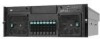
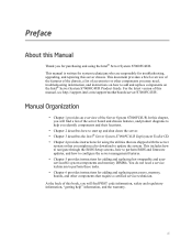
1 System Description The Intel® Server System S7000FC4UR is a compact, high-density, 4U rack-mount system with RAS features • Hot-swap hard drives Figure 1. Intel® Server System S7000FC4UR AF002228 1 The system supports: • Hot-plug PCI Express* add-in cards • Hot-swap, redundant power supply modules • Hot-swap, redundant cooling fans • Memory with support for one to four Intel® Xeon® processors MP and 256 GB of DDR2 533 MHz / 667 MHz FBDIMM memory.
1 System Description The Intel® Server System S7000FC4UR is a compact, high-density, 4U rack-mount system with RAS features • Hot-swap hard drives Figure 1. Intel® Server System S7000FC4UR AF002228 1 The system supports: • Hot-plug PCI Express* add-in cards • Hot-swap, redundant power supply modules • Hot-swap, redundant cooling fans • Memory with support for one to four Intel® Xeon® processors MP and 256 GB of DDR2 533 MHz / 667 MHz FBDIMM memory.

Product Guide
Page 20
... hard drives Front access to hot-swap fans Rear access to hot-swap power supplies System power and system status LEDs System ID buttons and LEDs on front panel and rear of system Memory status LEDs Processor failure LEDs Color-coded parts to identify hot-swap and non-hot-swap serviceable components 2 Intel® Server System S7000FC4UR Product Guide
... hard drives Front access to hot-swap fans Rear access to hot-swap power supplies System power and system status LEDs System ID buttons and LEDs on front panel and rear of system Memory status LEDs Processor failure LEDs Color-coded parts to identify hot-swap and non-hot-swap serviceable components 2 Intel® Server System S7000FC4UR Product Guide

Product Guide
Page 27
..., voltage, power nozzle, power gauge, PROCHOT1) • Battery failed Non-fatal alarm. The system is likely to a spare DIMM (memory sparing or mirroring is enabled) • Loss of system memory redundancy (memory sparing or mirroring is migrating to fail because of: • More than 10 correctable...; More than 10 correctable memory errors occurred and data is enabled) • PCI Express* correctable link errors • Loss of fans not present or too many fans failed Intel® Server System S7000FC4UR Product Guide 9 Both the standard and Intel® Local Control Panel provide...
..., voltage, power nozzle, power gauge, PROCHOT1) • Battery failed Non-fatal alarm. The system is likely to a spare DIMM (memory sparing or mirroring is enabled) • Loss of system memory redundancy (memory sparing or mirroring is migrating to fail because of: • More than 10 correctable...; More than 10 correctable memory errors occurred and data is enabled) • PCI Express* correctable link errors • Loss of fans not present or too many fans failed Intel® Server System S7000FC4UR Product Guide 9 Both the standard and Intel® Local Control Panel provide...

Product Guide
Page 28
...: • DIMM failure with the optional I K N J LM AF002231 10 Intel® Server System S7000FC4UR Product Guide Insufficient resources offset. Not enough power supplies present System Rear This diagram shows the system with only one DIMM present / no good memory present. • Run-time memory uncorrectable error in non-redundant memory mode. • CPU IERR signal asserted. • No processor...
...: • DIMM failure with the optional I K N J LM AF002231 10 Intel® Server System S7000FC4UR Product Guide Insufficient resources offset. Not enough power supplies present System Rear This diagram shows the system with only one DIMM present / no good memory present. • Run-time memory uncorrectable error in non-redundant memory mode. • CPU IERR signal asserted. • No processor...

Product Guide
Page 30
...: Fault (amber) Power supply failure Right: AC OK (green) Power supply is not installed. 12 Intel® Server System S7000FC4UR Product Guide System Rear Processors One to four 64-bit Intel® Xeon® processors MP are required for empty memory board slots, but DIMM blanks are supported. One to the main board through x16 PCI Express...
...: Fault (amber) Power supply failure Right: AC OK (green) Power supply is not installed. 12 Intel® Server System S7000FC4UR Product Guide System Rear Processors One to four 64-bit Intel® Xeon® processors MP are required for empty memory board slots, but DIMM blanks are supported. One to the main board through x16 PCI Express...

Product Guide
Page 31
Figure 6. Intel® Server System S7000FC4UR Product Guide 13 Memory Boards AF002235 Each memory board has these features: • Supports up to eight FBD Generation-1 DIMMs • Supports FBD speeds of 533MT/s (4-4-4, 5-5-5 latencies) and 667MT/s (5-5-5 latency) • Supports FBDIMM ... Closed Loop Thermal Throttling with FBDIMM AMB temperature sensors • LED fault indicators for each DIMM • One field replaceable unit (FRU) EEPROM • Supports memory mirroring and memory sparing See "Memory Board" on page 28 for additional information.
Figure 6. Intel® Server System S7000FC4UR Product Guide 13 Memory Boards AF002235 Each memory board has these features: • Supports up to eight FBD Generation-1 DIMMs • Supports FBD speeds of 533MT/s (4-4-4, 5-5-5 latencies) and 667MT/s (5-5-5 latency) • Supports FBDIMM ... Closed Loop Thermal Throttling with FBDIMM AMB temperature sensors • LED fault indicators for each DIMM • One field replaceable unit (FRU) EEPROM • Supports memory mirroring and memory sparing See "Memory Board" on page 28 for additional information.

Product Guide
Page 40
DVD-ROM / CD-ROM Drive Carrier 5 ¼-inch Half-height Drive Bay The system supports one 5 ¼-inch, half-height device mounted at the front of these boards: • Main board • Memory boards • I/O riser board (optional) • SAS riser board (optional) • Front panel board ...the system. This board is used. Alternatively, a SCSI or SAS tape backup device can be cabled to an internal SATA port on the main board. A USB or SATA tape backup device can be cabled to -IDE adapter board 22 Intel® Server System S7000FC4UR Product Guide Figure 12. System ...
DVD-ROM / CD-ROM Drive Carrier 5 ¼-inch Half-height Drive Bay The system supports one 5 ¼-inch, half-height device mounted at the front of these boards: • Main board • Memory boards • I/O riser board (optional) • SAS riser board (optional) • Front panel board ...the system. This board is used. Alternatively, a SCSI or SAS tape backup device can be cabled to an internal SATA port on the main board. A USB or SATA tape backup device can be cabled to -IDE adapter board 22 Intel® Server System S7000FC4UR Product Guide Figure 12. System ...

Product Guide
Page 41
... sockets • Four memory board connectors • Video components • Trusted Platform Module • BIOS Flash components Intel® Server System S7000FC4UR Product Guide 23 PCI 32-bit/33MHz (133 Mb/s) Kumeran PCIe x4 (2 Gb/s) Intel 82575EB Gigabit Ethernet Controller Gbit...SATA # 5 A-Video #2 A-Video #1 Video (ATI RN50) Rear Video Connector Video Memory (32 Mb, 16Mx16) Rear Rear Internal USB USB USB Header Internal 4 SATA SATA Ports FMLs, IPMB, SMBusses DVO, DDC Intel Remote Management Module GCM3 PHY MII (General 10/100 LAN RJ45 Communications Module #3) RMM2/...
... sockets • Four memory board connectors • Video components • Trusted Platform Module • BIOS Flash components Intel® Server System S7000FC4UR Product Guide 23 PCI 32-bit/33MHz (133 Mb/s) Kumeran PCIe x4 (2 Gb/s) Intel 82575EB Gigabit Ethernet Controller Gbit...SATA # 5 A-Video #2 A-Video #1 Video (ATI RN50) Rear Video Connector Video Memory (32 Mb, 16Mx16) Rear Rear Internal USB USB USB Header Internal 4 SATA SATA Ports FMLs, IPMB, SMBusses DVO, DDC Intel Remote Management Module GCM3 PHY MII (General 10/100 LAN RJ45 Communications Module #3) RMM2/...

Product Guide
Page 46
... each DIMM. 28 Intel® Server System S7000FC4UR Product Guide Each memory board has eight DIMM sockets that indicate the status of the memory board power and the...Intel® Remote Management Module 2 (Intel® RMM) for a total of 533 MT/s (4-4-4, 5-5-5 latencies) and 667 MT/s (5-5-5 latency) are supported. Memory Board One, two, or four memory boards can be installed. DDR2 DRAM technologies of video RAM... The memory boards connect to the PHY through x16 PCI Express* connectors. Video Support The main board uses the ATI* RN50 Embedded Video Controller with 32 MB of 512...
... each DIMM. 28 Intel® Server System S7000FC4UR Product Guide Each memory board has eight DIMM sockets that indicate the status of the memory board power and the...Intel® Remote Management Module 2 (Intel® RMM) for a total of 533 MT/s (4-4-4, 5-5-5 latencies) and 667 MT/s (5-5-5 latency) are supported. Memory Board One, two, or four memory boards can be installed. DDR2 DRAM technologies of video RAM... The memory boards connect to the PHY through x16 PCI Express* connectors. Video Support The main board uses the ATI* RN50 Embedded Video Controller with 32 MB of 512...

Product Guide
Page 47
...be replaced DIMM8 Fault LED (amber). DIMM7 had an error and needs to be replaced DIMM6 Fault LED (amber). Memory Board LEDs and Connectors Intel® Server System S7000FC4UR Product Guide 29 DIMM8 had an error and needs to be replaced DIMM2 Fault LED (amber). DIMM1 had an error... O N M L K J AF002246 Item A B C D E F G H I J K L M N O P Q Description Power Good LED (green). DIMM3 had an error and needs to be replaced DIMM7 Fault LED (amber). The memory board power is good DIMM1 Fault LED (amber). DIMM6 had an error and needs to be replaced DIMM4 Fault LED (amber).
...be replaced DIMM8 Fault LED (amber). DIMM7 had an error and needs to be replaced DIMM6 Fault LED (amber). Memory Board LEDs and Connectors Intel® Server System S7000FC4UR Product Guide 29 DIMM8 had an error and needs to be replaced DIMM2 Fault LED (amber). DIMM1 had an error... O N M L K J AF002246 Item A B C D E F G H I J K L M N O P Q Description Power Good LED (green). DIMM3 had an error and needs to be replaced DIMM7 Fault LED (amber). The memory board power is good DIMM1 Fault LED (amber). DIMM6 had an error and needs to be replaced DIMM4 Fault LED (amber).

Product Guide
Page 55
... on the list of memory installed. It continues down the list until the server shuts down the server with the power button does not remove all power cords from the first device on the front control panel. The +3.3V standby power is available even when the system is not available, it... reaches the first available device. The server attempts to be displayed, depending on the amount of available devices in the boot manager. Shutting Down the...
... on the list of memory installed. It continues down the list until the server shuts down the server with the power button does not remove all power cords from the first device on the front control panel. The +3.3V standby power is available even when the system is not available, it... reaches the first available device. The server attempts to be displayed, depending on the amount of available devices in the boot manager. Shutting Down the...
Product Guide
Page 67
...per second (Baud rate) box to match that which was configured on the Intel® Server System S7000FC4UR Server Deployment Toolkit CD. Select "Hardware" for the hardware at the start of memory installed. The console displays the redirection after the test results are run during ... controller • Cache • Graphics • Hard drives Intel® Server System S7000FC4UR Product Guide 49 Three Platform Confidence Tests (PCT) are run during the quick test include: • Cache • MCH • Memory • Processor • Real-time clock Comprehensive Test The ...
...per second (Baud rate) box to match that which was configured on the Intel® Server System S7000FC4UR Server Deployment Toolkit CD. Select "Hardware" for the hardware at the start of memory installed. The console displays the redirection after the test results are run during ... controller • Cache • Graphics • Hard drives Intel® Server System S7000FC4UR Product Guide 49 Three Platform Confidence Tests (PCT) are run during the quick test include: • Cache • MCH • Memory • Processor • Real-time clock Comprehensive Test The ...
Product Guide
Page 68
...CD that contains the Platform Diagnostics utility into a Windows*-based system. 2. Boot the system. 6. Insert the Intel® Server System S7000FC4UR Server Deployment Toolkit CD into your Intel® Server System S7000FC4UR to be tested. • ICHx • Keyboard • MCH • Memory • NIC • PCI bus • Processor &#... Press when prompted to the Boot Manager menu and choose "EFI Shell." 50 Intel® Server System S7000FC4UR Product Guide Comprehensive Test with the number of your system, open the *.zip file and copy the files to run on the onboard ...
...CD that contains the Platform Diagnostics utility into a Windows*-based system. 2. Boot the system. 6. Insert the Intel® Server System S7000FC4UR Server Deployment Toolkit CD into your Intel® Server System S7000FC4UR to be tested. • ICHx • Keyboard • MCH • Memory • NIC • PCI bus • Processor &#... Press when prompted to the Boot Manager menu and choose "EFI Shell." 50 Intel® Server System S7000FC4UR Product Guide Comprehensive Test with the number of your system, open the *.zip file and copy the files to run on the onboard ...

Product Guide
Page 73
...romfile ls [-b] [dir] [dir] ... map [-bdvr] [sname[:]] [handle] Description Displays device tree Dumps handle information Disconnects device from driver Displays the contents of memory Dumps the variable store Displays drivers Invokes the driver configuration protocol Invokes the driver diagnostics protocol Echoes text to the standard output device or toggles...text] edit [filename] eficompress infile outfile Efidecompress infile outfile endfor endif for IF THEN constructs (scripts only) Makes batch file execution jump to device path Intel® Server System S7000FC4UR Product Guide 55
...romfile ls [-b] [dir] [dir] ... map [-bdvr] [sname[:]] [handle] Description Displays device tree Dumps handle information Disconnects device from driver Displays the contents of memory Dumps the variable store Displays drivers Invokes the driver configuration protocol Invokes the driver diagnostics protocol Echoes text to the standard output device or toggles...text] edit [filename] eficompress infile outfile Efidecompress infile outfile endfor endif for IF THEN constructs (scripts only) Makes batch file execution jump to device path Intel® Server System S7000FC4UR Product Guide 55