
Product Guide
Page 1
Intel® Server System S7000FC4UR Product Guide A Guide for Technically Qualified Assemblers of Intel® Identified Subassemblies/Products Intel Order Number D93989-002
Intel® Server System S7000FC4UR Product Guide A Guide for Technically Qualified Assemblers of Intel® Identified Subassemblies/Products Intel Order Number D93989-002

Product Guide
Page 2
... countries. * Other names and brands may make changes to use in connection with Intel® products. Copyright © 2007, Intel Corporation. All Rights Reserved ii Intel® Server System S7000FC4UR Product Guide Intel, Intel Pentium, and Intel Xeon are not designed, intended or authorized for use Intel developed server building blocks to consult vendor datasheets and operating parameters to any intellectual property rights...
... countries. * Other names and brands may make changes to use in connection with Intel® products. Copyright © 2007, Intel Corporation. All Rights Reserved ii Intel® Server System S7000FC4UR Product Guide Intel, Intel Pentium, and Intel Xeon are not designed, intended or authorized for use Intel developed server building blocks to consult vendor datasheets and operating parameters to any intellectual property rights...

Product Guide
Page 4
... AC power cord is unplugged before opening it. Do not slide board over any components. iv Intel® Server System S7000FC4UR Product Guide Otherwise, personal injury or equipment damage can be present on a grounded, static free surface. They can result. Use of other products / components will void the UL listing and other regulatory approvals of the...
... AC power cord is unplugged before opening it. Do not slide board over any components. iv Intel® Server System S7000FC4UR Product Guide Otherwise, personal injury or equipment damage can be present on a grounded, static free surface. They can result. Use of other products / components will void the UL listing and other regulatory approvals of the...

Product Guide
Page 5
... removing jumpers: A jumper is a small plastic encased conductor that jumper. grip the narrow sides of the jumper with a pair of fine needle nosed pliers. Intel® Server System S7000FC4UR Product Guide v Take care to remove a jumper, or you can grip with your jumpers do not have a small tab on top that you may bend or...
... removing jumpers: A jumper is a small plastic encased conductor that jumper. grip the narrow sides of the jumper with a pair of fine needle nosed pliers. Intel® Server System S7000FC4UR Product Guide v Take care to remove a jumper, or you can grip with your jumpers do not have a small tab on top that you may bend or...
Product Guide
Page 7
..., and instructions on how to add and replace components on the Intel® Server System S7000FC4UR Product Guide. serviceable system components and memory DIMMs. You do not need a service technician to help " information, and the warranty. At the back of the server board and chassis features, and product diagrams to perform these tasks. • Chapter 6 provides instructions for...
..., and instructions on how to add and replace components on the Intel® Server System S7000FC4UR Product Guide. serviceable system components and memory DIMMs. You do not need a service technician to help " information, and the warranty. At the back of the server board and chassis features, and product diagrams to perform these tasks. • Chapter 6 provides instructions for...

Product Guide
Page 8
... software For drivers For firmware and BIOS updates For software to manage your Intel® server Use this Document or Software Intel® Server System S7000FC4UR Technical Product Specification Intel® Server System S7000FC4UR Quick Start User's Guide in the product box Spares and Configuration Guide Tested Hardware Operating Systems List Supported Processors Supported Memory Power Budget Platform Confidence Tests (PCT) Driver (for...
... software For drivers For firmware and BIOS updates For software to manage your Intel® server Use this Document or Software Intel® Server System S7000FC4UR Technical Product Specification Intel® Server System S7000FC4UR Quick Start User's Guide in the product box Spares and Configuration Guide Tested Hardware Operating Systems List Supported Processors Supported Memory Power Budget Platform Confidence Tests (PCT) Driver (for...

Product Guide
Page 9
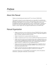
... Organization vii Additional Information and Software viii Chapter 1: System Description 1 System Features 2 System Front 4 Front Control Panel 5 System Rear 10 Processors 12 System Memory 12 Power Subsystem 14 Power Supply Modules 14 ...System Board Set 22 Main Board 23 Memory Board 28 I/O Riser Board (optional 30 SAS Riser Board (optional 31 Front Panel Board 32 SAS Backplane Board 33 Power Distribution Board 35 Server and Platform Management 35 Chapter 2: Starting Up and Shutting Down the Server 37 Powering Up the Server 37 Intel® Server System S7000FC4UR Product...
... Organization vii Additional Information and Software viii Chapter 1: System Description 1 System Features 2 System Front 4 Front Control Panel 5 System Rear 10 Processors 12 System Memory 12 Power Subsystem 14 Power Supply Modules 14 ...System Board Set 22 Main Board 23 Memory Board 28 I/O Riser Board (optional 30 SAS Riser Board (optional 31 Front Panel Board 32 SAS Backplane Board 33 Power Distribution Board 35 Server and Platform Management 35 Chapter 2: Starting Up and Shutting Down the Server 37 Powering Up the Server 37 Intel® Server System S7000FC4UR Product...
Product Guide
Page 10
...Keystroke Mappings 47 Limitations 48 Interface to Server Management 48 Platform Confidence Test 49 Running the Platform Confidence Test 50 Intel® Deployment Assistant 51 System Setup and Configuration Utilities 51 Save and Restore System Configuration (SYSCFG 52 FWPIAUPD Firmware Load Utility...Installing and Removing PCI Express* Add-in Cards 68 Removing a Hot-swap PCI Card, Operating System Interface 69 Removing a Hot-swap PCI Card, Hardware Interface 71 Installing a Hot-swap PCI Card 72 Removing a Non-hot-swap PCI Card 74 x Intel® Server System S7000FC4UR Product Guide
...Keystroke Mappings 47 Limitations 48 Interface to Server Management 48 Platform Confidence Test 49 Running the Platform Confidence Test 50 Intel® Deployment Assistant 51 System Setup and Configuration Utilities 51 Save and Restore System Configuration (SYSCFG 52 FWPIAUPD Firmware Load Utility...Installing and Removing PCI Express* Add-in Cards 68 Removing a Hot-swap PCI Card, Operating System Interface 69 Removing a Hot-swap PCI Card, Hardware Interface 71 Installing a Hot-swap PCI Card 72 Removing a Non-hot-swap PCI Card 74 x Intel® Server System S7000FC4UR Product Guide

Product Guide
Page 11
...81 Removing DIMMs 84 Chapter 6: Technician Maintenance 85 Before You Begin 85 Tools and Supplies Needed 85 System References 85 Component Locations 86 Removing and Installing the Top Cover 90 Removing the Top Cover 90 Installing...Intel® Xeon® Processor MP 110 Installing and Removing a Processor Thermal Blank 111 Removing a Processor Thermal Blank 111 Installing a Processor Thermal Blank 112 Installing and Removing a Processor 113 Installing a Processor 113 Removing a Processor 115 Removing and Installing the Center Brace 116 Intel® Server System S7000FC4UR Product...
...81 Removing DIMMs 84 Chapter 6: Technician Maintenance 85 Before You Begin 85 Tools and Supplies Needed 85 System References 85 Component Locations 86 Removing and Installing the Top Cover 90 Removing the Top Cover 90 Installing...Intel® Xeon® Processor MP 110 Installing and Removing a Processor Thermal Blank 111 Removing a Processor Thermal Blank 111 Installing a Processor Thermal Blank 112 Installing and Removing a Processor 113 Installing a Processor 113 Removing a Processor 115 Removing and Installing the Center Brace 116 Intel® Server System S7000FC4UR Product...

Product Guide
Page 12
... 118 Removing the I/O Riser Board 118 Installing and Removing the Intel® Remote Management Module 2 (Intel® RMM2 119 Installing the Intel® RMM2 and NIC Module 119 Removing the Intel® RMM2 and NIC Module 121 Replacing the Main Board 122... C: Safety Information 167 English ...167 Server Safety Information 167 Safety Warnings and Cautions 167 Intended Application Uses 168 Site Selection 168 Equipment Handling Practices 169 Power and Electrical Warnings 169 System Access Warnings 170 Rack Mount Warnings 171 xii Intel® Server System S7000FC4UR Product Guide
... 118 Removing the I/O Riser Board 118 Installing and Removing the Intel® Remote Management Module 2 (Intel® RMM2 119 Installing the Intel® RMM2 and NIC Module 119 Removing the Intel® RMM2 and NIC Module 121 Replacing the Main Board 122... C: Safety Information 167 English ...167 Server Safety Information 167 Safety Warnings and Cautions 167 Intended Application Uses 168 Site Selection 168 Equipment Handling Practices 169 Power and Electrical Warnings 169 System Access Warnings 170 Rack Mount Warnings 171 xii Intel® Server System S7000FC4UR Product Guide

Product Guide
Page 14
... (RoHS) Compliance 203 End of Life / Product Recycling 204 Appendix E: Equipment Log 205 Appendix F: Warranty 207 Limited Warranty for Intel® Chassis Subassembly Products 207 Extent of Limited Warranty 208 Warranty Limitations and... Exclusions 208 Limitations of Liability 208 How to Obtain Warranty Service 209 Telephone Support 209 Returning a Defective Product 209 Appendix G: Getting Help 211 World Wide Web 211 Telephone 211 xiv Intel® Server System S7000FC4UR Product...
... (RoHS) Compliance 203 End of Life / Product Recycling 204 Appendix E: Equipment Log 205 Appendix F: Warranty 207 Limited Warranty for Intel® Chassis Subassembly Products 207 Extent of Limited Warranty 208 Warranty Limitations and... Exclusions 208 Limitations of Liability 208 How to Obtain Warranty Service 209 Telephone Support 209 Returning a Defective Product 209 Appendix G: Getting Help 211 World Wide Web 211 Telephone 211 xiv Intel® Server System S7000FC4UR Product...

Product Guide
Page 15
.... Opening Memory Board Latches 76 Figure 39. Power Consumption Selection Jumper 16 Figure 9. Removing a PCI Card 70 Figure 36. Memory Board A and B Population 80 Intel® Server System S7000FC4UR Product Guide xv Hard Drive Carrier 62 Figure 28. Front Panel Board Component Locations 32 Figure 20. Removing the Air Baffle from the Hard Drive Carrier...
.... Opening Memory Board Latches 76 Figure 39. Power Consumption Selection Jumper 16 Figure 9. Removing a PCI Card 70 Figure 36. Memory Board A and B Population 80 Intel® Server System S7000FC4UR Product Guide xv Hard Drive Carrier 62 Figure 28. Front Panel Board Component Locations 32 Figure 20. Removing the Air Baffle from the Hard Drive Carrier...

Product Guide
Page 16
... from SAS Riser Board ........ 100 Figure 60. Removing 5 ¼-inch Peripheral Device from the Server 105 Figure 63. Installing 5 ¼ Peripheral Device into the System 107 Figure 66. Open Processor Socket Release Lever 115 Figure 74. Installing the Center Brace 117 .../ DVD-ROM Drive Carrier into Server 109 Figure 68. Set Processor into Socket 114 Figure 72. Installing the Intel® RMM2 121 Figure 79. Installing a Thermal Blank 112 Figure 70. Removing the Battery 135 xvi Intel® Server System S7000FC4UR Product Guide Removing the Main Board 124...
... from SAS Riser Board ........ 100 Figure 60. Removing 5 ¼-inch Peripheral Device from the Server 105 Figure 63. Installing 5 ¼ Peripheral Device into the System 107 Figure 66. Open Processor Socket Release Lever 115 Figure 74. Installing the Center Brace 117 .../ DVD-ROM Drive Carrier into Server 109 Figure 68. Set Processor into Socket 114 Figure 72. Installing the Intel® RMM2 121 Figure 79. Installing a Thermal Blank 112 Figure 70. Removing the Battery 135 xvi Intel® Server System S7000FC4UR Product Guide Removing the Main Board 124...

Product Guide
Page 17
System Status LED States 9 Table 4. Hot-swap PCI Slot Power and Attention LED 19 Table 5. Chassis Features 2 Table 3. Beep Codes 153 Table 12. Port 80 POST Code LEDs 137 Table 9. POST Progress Codes and Messages 138 Table 10. POST Error Manager Messages and Handling 142 Table 11. Product Regulatory Compliance Markings 198 Intel® Server System S7000FC4UR Product Guide xvii Console Redirection Escape Sequences 47 Table 7. Additional Information and Software viii Table 2. EFI Shell Commands 54 Table 8. Tables Table 1. Setup Menu Key Use 42 Table 6.
System Status LED States 9 Table 4. Hot-swap PCI Slot Power and Attention LED 19 Table 5. Chassis Features 2 Table 3. Beep Codes 153 Table 12. Port 80 POST Code LEDs 137 Table 9. POST Progress Codes and Messages 138 Table 10. POST Error Manager Messages and Handling 142 Table 11. Product Regulatory Compliance Markings 198 Intel® Server System S7000FC4UR Product Guide xvii Console Redirection Escape Sequences 47 Table 7. Additional Information and Software viii Table 2. EFI Shell Commands 54 Table 8. Tables Table 1. Setup Menu Key Use 42 Table 6.

Product Guide
Page 20
... LAN ports with optional I/O riser board The optional Intel® Local Control Panel provides an LCD display that allows you to configure and monitor the health of the server independently from the operating system Front access to hot-swap hard drives Front access to...-swap power supplies System power and system status LEDs System ID buttons and LEDs on front panel and rear of system Memory status LEDs Processor failure LEDs Color-coded parts to identify hot-swap and non-hot-swap serviceable components 2 Intel® Server System S7000FC4UR Product Guide System Features Feature Dimensions...
... LAN ports with optional I/O riser board The optional Intel® Local Control Panel provides an LCD display that allows you to configure and monitor the health of the server independently from the operating system Front access to hot-swap hard drives Front access to...-swap power supplies System power and system status LEDs System ID buttons and LEDs on front panel and rear of system Memory status LEDs Processor failure LEDs Color-coded parts to identify hot-swap and non-hot-swap serviceable components 2 Intel® Server System S7000FC4UR Product Guide System Features Feature Dimensions...

Product Guide
Page 21
... remote KVM and media features (requires optional I/O riser) System power button and LED System reset button NMI button System ID button and LED Optional Intel® Local Control Panel System status LED Hard drive status LED LAN1 and LAN2 status LEDs Video connector Three USB 2.0 ports Intel® Server System S7000FC4UR Product Guide 3 Chassis Features Description Two hot-plug PCI... power cords (1+1) when two power supplies are optional; SAS RAID riser board (optional) with a battery-backed DDR2 DIMM for redundancy. Up to eight hot-swap system fans in a redundant (1+1) configuration.
... remote KVM and media features (requires optional I/O riser) System power button and LED System reset button NMI button System ID button and LED Optional Intel® Local Control Panel System status LED Hard drive status LED LAN1 and LAN2 status LEDs Video connector Three USB 2.0 ports Intel® Server System S7000FC4UR Product Guide 3 Chassis Features Description Two hot-plug PCI... power cords (1+1) when two power supplies are optional; SAS RAID riser board (optional) with a battery-backed DDR2 DIMM for redundancy. Up to eight hot-swap system fans in a redundant (1+1) configuration.

Product Guide
Page 22
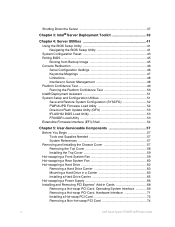
System Front A B CD E F G F AF002229 Item A B C D E F G Description CD-ROM / DVD-ROM drive bay 5 ¼-inch peripheral bay Video connector USB 2.0 ports Front control panel. Hot-swap fan modules (2) Hot-swap hard drives (8) Figure 2. Front Components 4 Intel® Server System S7000FC4UR Product Guide Standard control panel shown.
System Front A B CD E F G F AF002229 Item A B C D E F G Description CD-ROM / DVD-ROM drive bay 5 ¼-inch peripheral bay Video connector USB 2.0 ports Front control panel. Hot-swap fan modules (2) Hot-swap hard drives (8) Figure 2. Front Components 4 Intel® Server System S7000FC4UR Product Guide Standard control panel shown.

Product Guide
Page 23
... and status LEDs. Front Control Panel You can choose between the standard control panel or the Intel® Local Control Panel to monitor and control your system locally. Item Feature Description Front Panel Connectors A Video connector Standard VGA-compatible video port B Three USB...Green / amber LED that indicates hard drive activity and faults LED LED State Drive State Green on empty slot (~2.5 Hz) Intel® Server System S7000FC4UR Product Guide 5 Green blink SATA drives are installed and active Amber on Drive / slot failure Amber slow blink Predictive hard drive /...
... and status LEDs. Front Control Panel You can choose between the standard control panel or the Intel® Local Control Panel to monitor and control your system locally. Item Feature Description Front Panel Connectors A Video connector Standard VGA-compatible video port B Three USB...Green / amber LED that indicates hard drive activity and faults LED LED State Drive State Green on empty slot (~2.5 Hz) Intel® Server System S7000FC4UR Product Guide 5 Green blink SATA drives are installed and active Amber on Drive / slot failure Amber slow blink Predictive hard drive /...

Product Guide
Page 24
... operate Green blink Degraded System is in a degraded state Amber blink Non-fatal System is likely to fail Amber on Fatal System has failed G System power LED Green LED for system power status LED State System Power State ACPI Off Power off No On Power on or off Figure 3. Front Panel Controls and Indicators 6 Intel® Server System S7000FC4UR Product Guide
... operate Green blink Degraded System is in a degraded state Amber blink Non-fatal System is likely to fail Amber on Fatal System has failed G System power LED Green LED for system power status LED State System Power State ACPI Off Power off No On Power on or off Figure 3. Front Panel Controls and Indicators 6 Intel® Server System S7000FC4UR Product Guide

Product Guide
Page 25
... to identify the system through server management software G System power LED Green LED to show system status LED State System Power State ACPI Off Power off No On Power on No Off S4 / S5 Yes Blink S1 Yes On S0 Yes H System power button Toggles system power on and off Intel® Server System S7000FC4UR Product Guide 7 The optional Intel® Local Control...
... to identify the system through server management software G System power LED Green LED to show system status LED State System Power State ACPI Off Power off No On Power on No Off S4 / S5 Yes Blink S1 Yes On S0 Yes H System power button Toggles system power on and off Intel® Server System S7000FC4UR Product Guide 7 The optional Intel® Local Control...