Product Specification
Page 2
...36) - Updated Figure 21 SMBUS Block Diagram, revised components code name - Updated Appendix G - Revision History Intel® Server Boards S5520HC, S5500HCV, and S5520HCT TPS Revision History Date February 2008 March 2008 March 2008 April 2008 August 2008 Revision Number 0.1 0.3 0.5 ... 3.2 Updated product code and processor support related information. S5500HCV DIMM slot population change . Updated Section 3.3.4.1 Memory Reservation for S5520HCT - Updated Table 87 BMC Beep Codes - Updated Section 2.1, the feature set table - Updated Section 3.3.9 supported memory population...
...36) - Updated Figure 21 SMBUS Block Diagram, revised components code name - Updated Appendix G - Revision History Intel® Server Boards S5520HC, S5500HCV, and S5520HCT TPS Revision History Date February 2008 March 2008 March 2008 April 2008 August 2008 Revision Number 0.1 0.3 0.5 ... 3.2 Updated product code and processor support related information. S5500HCV DIMM slot population change . Updated Section 3.3.4.1 Memory Reservation for S5520HCT - Updated Table 87 BMC Beep Codes - Updated Section 2.1, the feature set table - Updated Section 3.3.9 supported memory population...
Product Specification
Page 3
... of others. Except as errata which may be held responsible if components fail or the server board does not operate correctly when used together. Intel® Server Boards S5520HC, S5500HCV, and S5520HCT TPS Disclaimers Disclaimers Information in this document. Refer to the Intel® Server Boards S5520HC, S5500HCV and S5520HCT Specification Update for future definition and shall have no liability whatsoever, and...
... of others. Except as errata which may be held responsible if components fail or the server board does not operate correctly when used together. Intel® Server Boards S5520HC, S5500HCV, and S5520HCT TPS Disclaimers Disclaimers Information in this document. Refer to the Intel® Server Boards S5520HC, S5500HCV and S5520HCT Specification Update for future definition and shall have no liability whatsoever, and...
Product Specification
Page 4
Introduction ...1 1.1 Chapter Outline ...1 1.2 Server Board Use Disclaimer 1 2. Functional Architecture...17 3.1 3.1.1 Intel® 5520 and 5500 I /O Layout 16 3. Overview ...2 2.1 Intel® Server Boards S5520HC, S5500HCV and S5520HCT Feature Set 2 2.1.1 Server Board Connector and Component Layout 5 2.1.2 Server Board Mechanical Drawings 8 2.1.3 Server Board Rear I /O Hub (IOH 20 Intel® QuickPath Interconnect 20 3.1.2 PCI Express* Ports 20 3.1.3 Enterprise South Bridge Interface (ESI 21 3.1.4 Manageability Engine (ME 21 3.1.5 Controller Link (CL...
Introduction ...1 1.1 Chapter Outline ...1 1.2 Server Board Use Disclaimer 1 2. Functional Architecture...17 3.1 3.1.1 Intel® 5520 and 5500 I /O Layout 16 3. Overview ...2 2.1 Intel® Server Boards S5520HC, S5500HCV and S5520HCT Feature Set 2 2.1.1 Server Board Connector and Component Layout 5 2.1.2 Server Board Mechanical Drawings 8 2.1.3 Server Board Rear I /O Hub (IOH 20 Intel® QuickPath Interconnect 20 3.1.2 PCI Express* Ports 20 3.1.3 Enterprise South Bridge Interface (ESI 21 3.1.4 Manageability Engine (ME 21 3.1.5 Controller Link (CL...
Product Specification
Page 5
... 4.3.1 Memory Open and Closed Loop Thermal Throttling 68 4.3.2 Fan Speed Control 68 4.4 Intel® Intelligent Power Node Manager 70 4.4.1 Manageability Engine (ME 70 5. Intel® Server Boards S5520HC, S5500HCV, and S5520HCT TPS Table of Contents 3.4.2 USB 2.0 Support ...41 3.5 PCI Subsystem...42 3.5.1 PCI Express* Riser Slot (S5520HC - BIOS Setup Utility ...72 5.1 Logo/Diagnostic Screen 72 5.2 BIOS Boot Popup...
... 4.3.1 Memory Open and Closed Loop Thermal Throttling 68 4.3.2 Fan Speed Control 68 4.4 Intel® Intelligent Power Node Manager 70 4.4.1 Manageability Engine (ME 70 5. Intel® Server Boards S5520HC, S5500HCV, and S5520HCT TPS Table of Contents 3.4.2 USB 2.0 Support ...41 3.5 PCI Subsystem...42 3.5.1 PCI Express* Riser Slot (S5520HC - BIOS Setup Utility ...72 5.1 Logo/Diagnostic Screen 72 5.2 BIOS Boot Popup...
Product Specification
Page 6
... Connectors 113 6.5.4 SAS Module Slot 113 6.5.5 Serial Port Connectors 114 6.5.6 USB Connector ...115 6.6 Fan Headers...116 7. Design and Environmental Specifications 128 9.1 Intel® Server Boards S5520HC, S5500HCV, and S5520HCT Design Specifications128 9.2 MTBF ...128 9.3 Server Board Power Requirements 130 9.3.1 Processor Power Support 131 9.4 Power Supply Output Requirements 131 9.4.1 Grounding...131 9.4.2 Stand-by LED 122 8.2 Fan Fault LED's...123...
... Connectors 113 6.5.4 SAS Module Slot 113 6.5.5 Serial Port Connectors 114 6.5.6 USB Connector ...115 6.6 Fan Headers...116 7. Design and Environmental Specifications 128 9.1 Intel® Server Boards S5520HC, S5500HCV, and S5520HCT Design Specifications128 9.2 MTBF ...128 9.3 Server Board Power Requirements 130 9.3.1 Processor Power Support 131 9.4 Power Supply Output Requirements 131 9.4.1 Grounding...131 9.4.2 Stand-by LED 122 8.2 Fan Fault LED's...123...
Product Specification
Page 7
... 9.4.7 Ripple/Noise ...133 9.4.8 Timing Requirements 133 9.4.9 Residual Voltage Immunity in Stand-by Mode 136 10. Intel® Server Boards S5520HC, S5500HCV, and S5520HCT TPS Table of -Life/Product Recycling 144 Appendix A: Integration and Usage Tips 145 Appendix B: Compatible Intel® Server Chassis 147 Appendix C: BMC Sensor Tables 150 Appendix D: Platform Specific BMC Appendix 160 Appendix E: POST Code...
... 9.4.7 Ripple/Noise ...133 9.4.8 Timing Requirements 133 9.4.9 Residual Voltage Immunity in Stand-by Mode 136 10. Intel® Server Boards S5520HC, S5500HCV, and S5520HCT TPS Table of -Life/Product Recycling 144 Appendix A: Integration and Usage Tips 145 Appendix B: Compatible Intel® Server Chassis 147 Appendix C: BMC Sensor Tables 150 Appendix D: Platform Specific BMC Appendix 160 Appendix E: POST Code...

Product Specification
Page 8
...Intel® Server Board S5520HC Functional Block Diagram 18 Figure 14. Intel® Server Board S5520HC DIMM Slots Arrangement 28 Figure 17. Configure RAS and Performance Screen Display 84 Figure 33. Serial Port Configuration Screen Display 87 Figure 35. USB Controller Configuration Screen Display 88 Figure 36. List of Figures Intel® Server Boards S5520HC, S5500HCV, and S5520HCT... TPS List of 2 9 Figure 6. Primary Side Card-Side Keep-out Zone 14 Figure 11. Intel® SAS Entry RAID ...
...Intel® Server Board S5520HC Functional Block Diagram 18 Figure 14. Intel® Server Board S5520HC DIMM Slots Arrangement 28 Figure 17. Configure RAS and Performance Screen Display 84 Figure 33. Serial Port Configuration Screen Display 87 Figure 35. USB Controller Configuration Screen Display 88 Figure 36. List of Figures Intel® Server Boards S5520HC, S5500HCV, and S5520HCT... TPS List of 2 9 Figure 6. Primary Side Card-Side Keep-out Zone 14 Figure 11. Intel® SAS Entry RAID ...

Product Specification
Page 9
... 134 Figure 61. Turn On/Off Timing (Power Supply Signals 135 Figure 62. Diagnostic LED Placement Diagram 161 Revision 1.8 ix Intel order number E39529-013 Server Management System Information Screen Display 98 Figure 42. Setup Utility - Setup Utility - Hard Disk Order Screen Display 102 Figure 46....BEV Device Order Screen Display 104 Figure 50. DIMM Fault LED's Location 126 Figure 58. Setup Utility - Setup Utility - Setup Utility - Intel® Server Boards S5520HC, S5500HCV, and S5520HCT TPS List of Figures Figure 40. POST Code Diagnostic LED Locations 127 Figure 59.
... 134 Figure 61. Turn On/Off Timing (Power Supply Signals 135 Figure 62. Diagnostic LED Placement Diagram 161 Revision 1.8 ix Intel order number E39529-013 Server Management System Information Screen Display 98 Figure 42. Setup Utility - Setup Utility - Hard Disk Order Screen Display 102 Figure 46....BEV Device Order Screen Display 104 Figure 50. DIMM Fault LED's Location 126 Figure 58. Setup Utility - Setup Utility - Setup Utility - Intel® Server Boards S5520HC, S5500HCV, and S5520HCT TPS List of Figures Figure 40. POST Code Diagnostic LED Locations 127 Figure 59.

Product Specification
Page 10
... Table 17. BIOS Setup: Keyboard Command Bar 74 Table 21. Processor Configuration Screen Fields 80 Table 24. Setup Utility - Server Management System Information Fields 98 Table 35. List of Tables Intel® Server Boards S5520HC, S5500HCV, and S5520HCT TPS List of Tables Table 1. Setup Utility - Memory Running Frequency vs. Setup Utility - System Acoustic and Performance Configuration...
... Table 17. BIOS Setup: Keyboard Command Bar 74 Table 21. Processor Configuration Screen Fields 80 Table 24. Setup Utility - Server Management System Information Fields 98 Table 35. List of Tables Intel® Server Boards S5520HC, S5500HCV, and S5520HCT TPS List of Tables Table 1. Setup Utility - Memory Running Frequency vs. Setup Utility - System Acoustic and Performance Configuration...
Product Specification
Page 11
... 55. VGA Connector Pin-out (J7A1 112 Table 57. SSI 4-pin Fan Header Pin-out (J7K1, J9A2, J9A3 117 Table 68. Server Board Design Specifications 128 Table 72. Voltage Regulation Limits 132 Table 76. Setup Utility - CPU 1 Power Connector Pin-out (J9A1 109 Table 49...Connector Pin-out (J1E3, J1G1, J1G4, J1G5, J1F1, J1F4 113 Table 59. Server Board Jumpers (J1E6, J1E2, J1E4, J1E5, J1H1 118 Table 70. MTBF Estimate ...129 Table 73. Intel® Server Boards S5520HC, S5500HCV, and S5520HCT TPS List of Internal Low-Profile USB Connector for Solid State Drive (J2D2 116 Table...
... 55. VGA Connector Pin-out (J7A1 112 Table 57. SSI 4-pin Fan Header Pin-out (J7K1, J9A2, J9A3 117 Table 68. Server Board Design Specifications 128 Table 72. Voltage Regulation Limits 132 Table 76. Setup Utility - CPU 1 Power Connector Pin-out (J9A1 109 Table 49...Connector Pin-out (J1E3, J1G1, J1G4, J1G5, J1F1, J1F4 113 Table 59. Server Board Jumpers (J1E6, J1E2, J1E4, J1E5, J1H1 118 Table 70. MTBF Estimate ...129 Table 73. Intel® Server Boards S5520HC, S5500HCV, and S5520HCT TPS List of Internal Low-Profile USB Connector for Solid State Drive (J2D2 116 Table...
Product Specification
Page 12
Platform Specific BMC Features 160 Table 84. POST Codes and Messages 162 Table 86. BMC Beep Codes ...169 xii Revision 1.8 Intel order number E39529-013 POST Error Beep Codes 169 Table 88. POST Progress Code LED Example 161 Table 85. Compatible Chassis/Heatsink Matrix 147 Table 82. POST Error Messages and Handling 166 Table 87. Integrated BMC Core Sensors 152 Table 83. List of Tables Intel® Server Boards S5520HC, S5500HCV, and S5520HCT TPS Table 80. Turn On/Off Timing ...135 Table 81.
Platform Specific BMC Features 160 Table 84. POST Codes and Messages 162 Table 86. BMC Beep Codes ...169 xii Revision 1.8 Intel order number E39529-013 POST Error Beep Codes 169 Table 88. POST Progress Code LED Example 161 Table 85. Compatible Chassis/Heatsink Matrix 147 Table 82. POST Error Messages and Handling 166 Table 87. Integrated BMC Core Sensors 152 Table 83. List of Tables Intel® Server Boards S5520HC, S5500HCV, and S5520HCT TPS Table 80. Turn On/Off Timing ...135 Table 81.
Product Specification
Page 13
Intel® Server Boards S5520HC, S5500HCV, and S5520HCT TPS List of Tables Revision 1.8 xiii Intel order number E39529-013
Intel® Server Boards S5520HC, S5500HCV, and S5520HCT TPS List of Tables Revision 1.8 xiii Intel order number E39529-013
Product Specification
Page 15
...; Chapter 3 - Intel® Light Guided Diagnostics ƒ Chapter 9 - POST Code Diagnostic LED Decoder ƒ Appendix F - Intel Corporation cannot be held responsible if components fail or the server board does not operate correctly when used together, the fully integrated system meets the intended thermal requirements of the Intel® Server Boards S5520HC, S5500HCV and S5520HCT. Intel® Server Boards S5520HC, S5500HCV, and S5520HCT TPS Introduction 1.
...; Chapter 3 - Intel® Light Guided Diagnostics ƒ Chapter 9 - POST Code Diagnostic LED Decoder ƒ Appendix F - Intel Corporation cannot be held responsible if components fail or the server board does not operate correctly when used together, the fully integrated system meets the intended thermal requirements of the Intel® Server Boards S5520HC, S5500HCV and S5520HCT. Intel® Server Boards S5520HC, S5500HCV, and S5520HCT TPS Introduction 1.

Product Specification
Page 16
... • Intel® Server Board S5520HC/S5520HCT: ƒ 12 DIMM slots ƒ Two DIMM slots per channel • Intel® Server Board S5500HCV ƒ Nine DIMM slots ƒ Two DIMM slots on Channels A, B, and C ƒ One DIMM slot on Channels D, E, and F • Intel® Server Board S5520HC/S5520HCT: ƒ Intel® 5520 Chipset ƒ Intel® 82801JIR I/O Controller Hub (ICH10R) • Intel® Server Board S5500HCV: ƒ Intel®...
... • Intel® Server Board S5520HC/S5520HCT: ƒ 12 DIMM slots ƒ Two DIMM slots per channel • Intel® Server Board S5500HCV ƒ Nine DIMM slots ƒ Two DIMM slots on Channels A, B, and C ƒ One DIMM slot on Channels D, E, and F • Intel® Server Board S5520HC/S5520HCT: ƒ Intel® 5520 Chipset ƒ Intel® 82801JIR I/O Controller Hub (ICH10R) • Intel® Server Board S5500HCV: ƒ Intel®...

Product Specification
Page 17
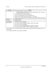
Intel® Server Boards S5520HC, S5500HCV, and S5520HCT TPS Overview Feature Add-in Card Slots Description • Intel® Server Board S5520HC/S5520HCT: Six expansion slots ƒ One full-length/full-height PCI Express* Gen2 slot (x16 Mechanically, x8 Electrically) ƒ Three... PCI add-in card Hard Drive and Optical Drive Support RAID Support USB Drive Support I/O control support Video Support LAN Security** • Intel® Server Board S5500HCV: Five expansion slots ƒ One full-length/full-height PCI Express* Gen2 slot (x16 Mechanically, x4 Electrically) ƒ Two ...
Intel® Server Boards S5520HC, S5500HCV, and S5520HCT TPS Overview Feature Add-in Card Slots Description • Intel® Server Board S5520HC/S5520HCT: Six expansion slots ƒ One full-length/full-height PCI Express* Gen2 slot (x16 Mechanically, x8 Electrically) ƒ Three... PCI add-in card Hard Drive and Optical Drive Support RAID Support USB Drive Support I/O control support Video Support LAN Security** • Intel® Server Board S5500HCV: Five expansion slots ƒ One full-length/full-height PCI Express* Gen2 slot (x16 Mechanically, x4 Electrically) ƒ Two ...
Product Specification
Page 18
Overview Intel® Server Boards S5520HC, S5500HCV, and S5520HCT TPS Feature Server Management BIOS Flash Form Factor Compatible Intel® Server Chassis Description • Onboard ServerEngines* LLC Pilot II* Controller ƒ Integrated Baseboard Management Controller (Integrated BMC), IPMI 2.0 compliant ƒ Integrated Super I/O on LPC interface • Support for Intel® Remote Management Module 3 • Intel® Light-Guided Diagnostics on field...
Overview Intel® Server Boards S5520HC, S5500HCV, and S5520HCT TPS Feature Server Management BIOS Flash Form Factor Compatible Intel® Server Chassis Description • Onboard ServerEngines* LLC Pilot II* Controller ƒ Integrated Baseboard Management Controller (Integrated BMC), IPMI 2.0 compliant ƒ Integrated Super I/O on LPC interface • Support for Intel® Remote Management Module 3 • Intel® Light-Guided Diagnostics on field...
Product Specification
Page 19
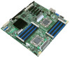
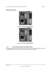
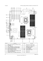
Intel® Server Board S5520HC Figure 2. Each connector and major component is identified by a number or letter, and a description is given below the figure. Intel® Server Board S5500HCV 2.1.1 Server Board Connector and Component Layout The following figure shows the layout of the server board. Revision 1.8 5 Intel order number E39529-013 Intel® Server Boards S5520HC, S5500HCV, and S5520HCT TPS Server Board Layout Overview Figure 1.
Intel® Server Board S5520HC Figure 2. Each connector and major component is identified by a number or letter, and a description is given below the figure. Intel® Server Board S5500HCV 2.1.1 Server Board Connector and Component Layout The following figure shows the layout of the server board. Revision 1.8 5 Intel order number E39529-013 Intel® Server Boards S5520HC, S5500HCV, and S5520HCT TPS Server Board Layout Overview Figure 1.
Product Specification
Page 20
...; Server Boards S5520HC, S5500HCV, and S5520HCT TPS Callout A B C D E F G H Description Slot 1, 32-bit/33 MHz PCI, Keying for 5V and Universal Intel® RMM3 Slot Slot 2, PCI Express* x4 (x8 Mechanically) Low-profile USB Solid State Drive Header Slot 3, PCI Express* Gen2 x8 Slot 4, PCI Express* Gen2 x8 Slot 5, PCI Express* Gen2 x8 (Empty on Intel® Server Board...
...; Server Boards S5520HC, S5500HCV, and S5520HCT TPS Callout A B C D E F G H Description Slot 1, 32-bit/33 MHz PCI, Keying for 5V and Universal Intel® RMM3 Slot Slot 2, PCI Express* x4 (x8 Mechanically) Low-profile USB Solid State Drive Header Slot 3, PCI Express* Gen2 x8 Slot 4, PCI Express* Gen2 x8 Slot 5, PCI Express* Gen2 x8 (Empty on Intel® Server Board...
Product Specification
Page 21
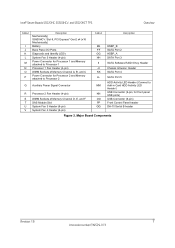
Intel® Server Boards S5520HC, S5500HCV, and S5520HCT TPS Overview Callout I J K L M N O P Description Mechanically) S5500HCV: Slot 6, PCI Express* Gen2 x4 (x16 Mechanically) Battery Back Panel I/O Ports Diagnostic and Identify LED's System Fan 5 Header (4-pin) ...) NN USB Connector (9-pin, for front panel USB ports) OO USB Connector (9-pin) PP Front Control Panel header QQ DH-10 Serial B header Figure 3. Major Board Components Revision 1.8 7 Intel order number E39529-013
Intel® Server Boards S5520HC, S5500HCV, and S5520HCT TPS Overview Callout I J K L M N O P Description Mechanically) S5500HCV: Slot 6, PCI Express* Gen2 x4 (x16 Mechanically) Battery Back Panel I/O Ports Diagnostic and Identify LED's System Fan 5 Header (4-pin) ...) NN USB Connector (9-pin, for front panel USB ports) OO USB Connector (9-pin) PP Front Control Panel header QQ DH-10 Serial B header Figure 3. Major Board Components Revision 1.8 7 Intel order number E39529-013
Product Specification
Page 22
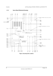
Mounting Hole Locations 8 Revision 1.8 Intel order number E39529-013 Overview 2.1.2 Intel® Server Boards S5520HC, S5500HCV, and S5520HCT TPS Server Board Mechanical Drawings Figure 4.
Mounting Hole Locations 8 Revision 1.8 Intel order number E39529-013 Overview 2.1.2 Intel® Server Boards S5520HC, S5500HCV, and S5520HCT TPS Server Board Mechanical Drawings Figure 4.


