
Product Specification
Page 2
...in this document. It is the responsibility of Table 16. Disclaimers Information in connection with Intel® products. Current characterized errata are not intended for quad rank memory and corrected the title of the system integrator that need adequate airflow to fitness for ...their published operating or non-operating limits. Designers must not rely on request. Intel® Workstation Board S5000XVN TPS Revision History...
...in this document. It is the responsibility of Table 16. Disclaimers Information in connection with Intel® products. Current characterized errata are not intended for quad rank memory and corrected the title of the system integrator that need adequate airflow to fitness for ...their published operating or non-operating limits. Designers must not rely on request. Intel® Workstation Board S5000XVN TPS Revision History...

Product Specification
Page 3
......31 System Health Support 32 3.6.6 Trusted Platform Module (TPM 32 4. Platform Management...33 Revision 1.5 iii Intel order number: D66403-006 Functional Architecture ...13 3.1 Intel® 5000X Memory Controller Hub (MCH 14 3.1.1 3.1.2 3.1.3 3.1.4 System Bus Interface 14 Processor Support 14 Memory Subsystem 16 Snoop Filter ...24 3.2 Enterprise South Bridge (ESB2-E 24 3.2.1 PCI Subsystem ...24 3.2.2 Serial ATA...
......31 System Health Support 32 3.6.6 Trusted Platform Module (TPM 32 4. Platform Management...33 Revision 1.5 iii Intel order number: D66403-006 Functional Architecture ...13 3.1 Intel® 5000X Memory Controller Hub (MCH 14 3.1.1 3.1.2 3.1.3 3.1.4 System Bus Interface 14 Processor Support 14 Memory Subsystem 16 Snoop Filter ...24 3.2 Enterprise South Bridge (ESB2-E 24 3.2.1 PCI Subsystem ...24 3.2.2 Serial ATA...
Product Specification
Page 6
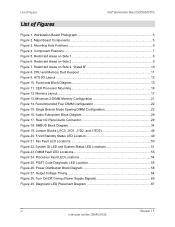
...Status LED Locations 51 Figure 23. Power Distribution Block Diagram 58 Figure 27. Component Positions...7 Figure 5. CPU and Memory Duct Keepout 11 Figure 9. Processor Fault LED Locations 54 Figure 25. Mounting Hole Positions 6 Figure 4. Restricted Areas on Side 1 8 Figure...15. DIMM Fault LED Locations 53 Figure 24. Fan Fault LED Locations 50 Figure 22. Diagnostic LED Placement Diagram 87 vi Revision 1.5 Intel order number: D66403-006 ATX I /O Panel Audio Connector 29 Figure 18. Audio Subsystem Block Diagram 28 Figure 17. Single Branch Mode...
...Status LED Locations 51 Figure 23. Power Distribution Block Diagram 58 Figure 27. Component Positions...7 Figure 5. CPU and Memory Duct Keepout 11 Figure 9. Processor Fault LED Locations 54 Figure 25. Mounting Hole Positions 6 Figure 4. Restricted Areas on Side 1 8 Figure...15. DIMM Fault LED Locations 53 Figure 24. Fan Fault LED Locations 50 Figure 22. Diagnostic LED Placement Diagram 87 vi Revision 1.5 Intel order number: D66403-006 ATX I /O Panel Audio Connector 29 Figure 18. Audio Subsystem Block Diagram 28 Figure 17. Single Branch Mode...

Product Specification
Page 7
...pin Serial B Header Pin-out (J1B1 42 Table 28. Stacked PS/2 Keyboard and Mouse Port Pin-out (J9A1 42 Table 29. Maximum Eight-DIMM System Memory Configuration - Power Connector Pin-out (J9B5 36 Table 13. 12-V Power Connector Pin-out (J3J2 37 Table 14. P12V4 Power Connector Pin-out (J5A2...Pin-out (J1E4 39 Table 23. SSI 4-pin Fan Header Pin-out (J9J1, J5J1, J9B3, and J9B4 44 Revision 1.5 vii Intel order number: D66403-006 Maximum Eight-DIMM System Memory Configruation - HSBP Header Pin-out (J1J7, J1J2 38 Table 19. SES I2C Header Pin-out (J1J3 38 Table 21. HDD Activity...
...pin Serial B Header Pin-out (J1B1 42 Table 28. Stacked PS/2 Keyboard and Mouse Port Pin-out (J9A1 42 Table 29. Maximum Eight-DIMM System Memory Configuration - Power Connector Pin-out (J9B5 36 Table 13. 12-V Power Connector Pin-out (J3J2 37 Table 14. P12V4 Power Connector Pin-out (J5A2...Pin-out (J1E4 39 Table 23. SSI 4-pin Fan Header Pin-out (J9J1, J5J1, J9B3, and J9B4 44 Revision 1.5 vii Intel order number: D66403-006 Maximum Eight-DIMM System Memory Configruation - HSBP Header Pin-out (J1J7, J1J2 38 Table 19. SES I2C Header Pin-out (J1J3 38 Table 21. HDD Activity...
Product Specification
Page 11
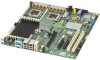
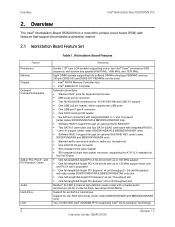
... FBDIMMs can be used. ƒ Intel® 5000X Memory Controller Hub ƒ Intel® ESB2-E I /O Acceleration Technology 2 Revision 1.5 Intel order number: D66403-006 Overview Intel® Workstation Board S5000XVN TPS 2. Workstation Board Features Feature Processors Memory Chipset Onboard Connectors/Headers Add-in ,... ƒ One DH10 serial port B header ƒ Six SATA-2 connectors with integrated RAID 0, 1, and 10 support (order codes S5000XVNSATAR & BB5000XVNSATAR only) ƒ Software RAID 5 support through an optional SATA RAID KEY ƒ Two SATA-2 connectors and four SATA-2/...
... FBDIMMs can be used. ƒ Intel® 5000X Memory Controller Hub ƒ Intel® ESB2-E I /O Acceleration Technology 2 Revision 1.5 Intel order number: D66403-006 Overview Intel® Workstation Board S5000XVN TPS 2. Workstation Board Features Feature Processors Memory Chipset Onboard Connectors/Headers Add-in ,... ƒ One DH10 serial port B header ƒ Six SATA-2 connectors with integrated RAID 0, 1, and 10 support (order codes S5000XVNSATAR & BB5000XVNSATAR only) ƒ Software RAID 5 support through an optional SATA RAID KEY ƒ Two SATA-2 connectors and four SATA-2/...
Product Specification
Page 20
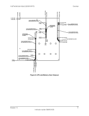
CPU and Memory Duct Keepout Revision 1.5 11 Intel order number: D66403-006 Intel® Workstation Board S5000XVN TPS Overview 188.152 [7.4076] 193.152 [7.6044] 273.091 [10.7516] 288.290 [11.3500] 16.510 [0.6500] 0.000 [0.0000] ...
CPU and Memory Duct Keepout Revision 1.5 11 Intel order number: D66403-006 Intel® Workstation Board S5000XVN TPS Overview 188.152 [7.4076] 193.152 [7.6044] 273.091 [10.7516] 288.290 [11.3500] 16.510 [0.6500] 0.000 [0.0000] ...

Product Specification
Page 22
... MHz, and 1333 MHz. For more information about the functional architecture blocks, see the Intel® S5000 Server Board Family Datasheet. This chipset is based on the Intel® S5000X chipset. The chipset contains two main components: the Memory Controller Hub (MCH) for the host bridge and the I/O controller hub for the I /O subsystem...
... MHz, and 1333 MHz. For more information about the functional architecture blocks, see the Intel® S5000 Server Board Family Datasheet. This chipset is based on the Intel® S5000X chipset. The chipset contains two main components: the Memory Controller Hub (MCH) for the host bridge and the I/O controller hub for the I /O subsystem...

Product Specification
Page 23
... the MCH uses a 64-bit wide 667, 1066, or 1333 MHz data bus. You can obtain additional information from the Intel S5000 Server Board Family Datasheet and the Intel 5000 Series Chipset Memory Controller Hub Datasheet. 3.1.1 System Bus Interface The MCH is optimized for symmetric multi-processing across two independent front side bus...
... the MCH uses a 64-bit wide 667, 1066, or 1333 MHz data bus. You can obtain additional information from the Intel S5000 Server Board Family Datasheet and the Intel 5000 Series Chipset Memory Controller Hub Datasheet. 3.1.1 System Bus Interface The MCH is optimized for symmetric multi-processing across two independent front side bus...

Product Specification
Page 25
...number: D66403-006 The two channels on each branch operate in lock-step to as a channel. Peak theoretical memory data bandwidth is supported by a separate memory controller. On the Intel® Workstation Board S5000XVN, a pair of channels becomes a branch where Branch 0 consists of channels A ...and B, and Branch 1 consists of supporting registered DDR2-533 and DDR2-667 FBDIMM memory (stacked or unstacked). Functional Architecture Intel® Workstation Board S5000XVN TPS Figure 11. Each branch is 6.4GB/s with DDR2-533 and 8.0GB/s with DDR2667. FBD...
...number: D66403-006 The two channels on each branch operate in lock-step to as a channel. Peak theoretical memory data bandwidth is supported by a separate memory controller. On the Intel® Workstation Board S5000XVN, a pair of channels becomes a branch where Branch 0 consists of channels A ...and B, and Branch 1 consists of supporting registered DDR2-533 and DDR2-667 FBDIMM memory (stacked or unstacked). Functional Architecture Intel® Workstation Board S5000XVN TPS Figure 11. Each branch is 6.4GB/s with DDR2-533 and 8.0GB/s with DDR2667. FBD...

Product Specification
Page 26
... system BIOS on the workstation board uses a dedicated I2C bus to retrieve DIMM information needed to program the MCH memory registers. The following table provides the I2C addresses for Memory Module SMB Device DIMM A1 DIMM A2 DIMM B1 DIMM B2 DIMM C1 DIMM C2 DIMM D1 DIMM D2 Address 0xA0... 0xA2 0xA0 0xA2 0xA0 0xA2 0xA0 0xA2 Revision 1.5 17 Intel order number: D66403-006 Intel® Workstation Board S5000XVN TPS Channel B Channel A...
... system BIOS on the workstation board uses a dedicated I2C bus to retrieve DIMM information needed to program the MCH memory registers. The following table provides the I2C addresses for Memory Module SMB Device DIMM A1 DIMM A2 DIMM B1 DIMM B2 DIMM C1 DIMM C2 DIMM D1 DIMM D2 Address 0xA0... 0xA2 0xA0 0xA2 0xA0 0xA2 0xA0 0xA2 Revision 1.5 17 Intel order number: D66403-006 Intel® Workstation Board S5000XVN TPS Channel B Channel A...

Product Specification
Page 27
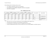
... Mb 1 GB 2 GB 4 GB 8 GB 2 GB 4 GB 8 GB 16 GB Table 5. Functional Architecture Intel® Workstation Board S5000XVN TPS 3.1.3.1 Memory RASUM Features The MCH supports several memory RASUM (Reliability, Availability, Serviceability, Usability, and Manageability) features. Maximum Eight-DIMM System Memory Configuration - x4 Dual Rank DRAM Technology x4 Dual Rank Maximum Capacity Mirrored Mode Maximum...
... Mb 1 GB 2 GB 4 GB 8 GB 2 GB 4 GB 8 GB 16 GB Table 5. Functional Architecture Intel® Workstation Board S5000XVN TPS 3.1.3.1 Memory RASUM Features The MCH supports several memory RASUM (Reliability, Availability, Serviceability, Usability, and Manageability) features. Maximum Eight-DIMM System Memory Configuration - x4 Dual Rank DRAM Technology x4 Dual Rank Maximum Capacity Mirrored Mode Maximum...

Product Specification
Page 28
... may have 512 MB FBDIMMs installed in DIMM sockets A1 and B1, and 1 GB FBDIMMs installed in pairs. Revision 1.5 19 Intel order number: D66403-006 You must be different between different DIMM pairs. However, DIMM capacities can be identical with respect to size... Functional Architecture Note: This workstation board supports only fully buffered DDR2 DIMMs (FBDIMMs. See the Intel® Workstation Board S5000XVN Tested Memory List for a list of supported memory for this server board. 3.1.3.3 DIMM Population Rules and Supported DIMM Configurations DIMM population rules depend ...
... may have 512 MB FBDIMMs installed in DIMM sockets A1 and B1, and 1 GB FBDIMMs installed in pairs. Revision 1.5 19 Intel order number: D66403-006 You must be different between different DIMM pairs. However, DIMM capacities can be identical with respect to size... Functional Architecture Note: This workstation board supports only fully buffered DDR2 DIMMs (FBDIMMs. See the Intel® Workstation Board S5000XVN Tested Memory List for a list of supported memory for this server board. 3.1.3.3 DIMM Population Rules and Supported DIMM Configurations DIMM population rules depend ...
Product Specification
Page 29
... ƒ NP: Slot is only tested and supported with a 512 MB x8 FBDIMM installed in mixed DIMM configurations. 20 Revision 1.5 Intel order number: D66403-006 DIMM Population Rules Branch 0 Channel A Channel B DIMM_A1 DIMM_A2 DIMM_B1 DIMM B2 VP NP NP NP VP NP... VP, Yes, Branch 0 and Branch 1 Notes: ƒ ƒ ƒ ƒ Single channel mode is not populated Table 7. The supported memory configurations must meet population rules defined above. Functional Architecture Intel® Workstation Board S5000XVN TPS In the following table, the following codes are supported...
... ƒ NP: Slot is only tested and supported with a 512 MB x8 FBDIMM installed in mixed DIMM configurations. 20 Revision 1.5 Intel order number: D66403-006 DIMM Population Rules Branch 0 Channel A Channel B DIMM_A1 DIMM_A2 DIMM_B1 DIMM B2 VP NP NP NP VP NP... VP, Yes, Branch 0 and Branch 1 Notes: ƒ ƒ ƒ ƒ Single channel mode is not populated Table 7. The supported memory configurations must meet population rules defined above. Functional Architecture Intel® Workstation Board S5000XVN TPS In the following table, the following codes are supported...
Product Specification
Page 30
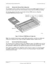
...When adding two DIMMs to size, speed, and organization. The following diagram. Minimum 2-DIMM Memory Configuration Note: The workstation board supports single DIMM mode operation. Revision 1.5 21 Intel order number: D66403-006 DIMMs pairs must cover the same slot position on both channels. Populated... DIMM sockets are shown in the following diagram shows the recommended minimum DIMM memory configuration. Intel will only validate and support this configuration with respect to the configuration shown in Figure 13 (above), you should ...
...When adding two DIMMs to size, speed, and organization. The following diagram. Minimum 2-DIMM Memory Configuration Note: The workstation board supports single DIMM mode operation. Revision 1.5 21 Intel order number: D66403-006 DIMMs pairs must cover the same slot position on both channels. Populated... DIMM sockets are shown in the following diagram shows the recommended minimum DIMM memory configuration. Intel will only validate and support this configuration with respect to the configuration shown in Figure 13 (above), you should ...

Product Specification
Page 31
... Configuration Functionally, DIMM sockets A2 and B2 could have been populated instead of speed. There are two supported memory sparing configurations. ƒ Single Branch Mode Sparing ƒ Dual Branch Mode Sparing 22 Revision 1.5 Intel order number: D66403-006 The MCH adjusts to the first with respect to size, speed, and organization. All...
... Configuration Functionally, DIMM sockets A2 and B2 could have been populated instead of speed. There are two supported memory sparing configurations. ƒ Single Branch Mode Sparing ƒ Dual Branch Mode Sparing 22 Revision 1.5 Intel order number: D66403-006 The MCH adjusts to the first with respect to size, speed, and organization. All...

Product Specification
Page 32
Revision 1.5 23 Intel order number: D66403-006 Single Branch Mode Sparing DIMM Configuration ƒ DIMM_A1 and DIMM_B1 must be identical in organization, size, and speed. ƒ DIMM_A2 and ... Rank Sparing Mode. ƒ The larger of the pairs {DIMM_A1, DIMM_B1}, {DIMM_A2, DIMM_B2}, {DIMM_C1, DIMM_D1}, and {DIMM_C2, DIMM_D2} are selected as the spare pair units. Intel® Workstation Board S5000XVN TPS 3.1.3.4.2.1 Single Branch Mode Sparing Slot 2 DIMM_A2 Slot 1 DIMM_A1 DIMM_B2 DIMM_B1 Channel A Channel B Branch 0 Functional Architecture DIMM_C2 DIMM_C1 DIMM_D2 DIMM_D1 Channel...
Revision 1.5 23 Intel order number: D66403-006 Single Branch Mode Sparing DIMM Configuration ƒ DIMM_A1 and DIMM_B1 must be identical in organization, size, and speed. ƒ DIMM_A2 and ... Rank Sparing Mode. ƒ The larger of the pairs {DIMM_A1, DIMM_B1}, {DIMM_A2, DIMM_B2}, {DIMM_C1, DIMM_D1}, and {DIMM_C2, DIMM_D2} are selected as the spare pair units. Intel® Workstation Board S5000XVN TPS 3.1.3.4.2.1 Single Branch Mode Sparing Slot 2 DIMM_A2 Slot 1 DIMM_A1 DIMM_B2 DIMM_B1 Channel A Channel B Branch 0 Functional Architecture DIMM_C2 DIMM_C1 DIMM_D2 DIMM_D1 Channel...

Product Specification
Page 38
... as described in the Serial Attached SCSI Standard, version 1.0. For SATA workstation boards, all six SATA connectors are used for SAS functionality. Intel® Workstation Board S5000XVN TPS Functional Architecture The workstation board supports the following audio connections through the rear I /O Panel Audio Connector The ...with support for dual LAN ports designed for 10/100/1000 Mbps operation. The SAS1064e controller supports a 32-bit external memory bus that provides an interface for Flash ROM and NVSRAM devices. 3.4.1 SAS RAID Support RAID modes 0, 1, and 10 are supported.
... as described in the Serial Attached SCSI Standard, version 1.0. For SATA workstation boards, all six SATA connectors are used for SAS functionality. Intel® Workstation Board S5000XVN TPS Functional Architecture The workstation board supports the following audio connections through the rear I /O Panel Audio Connector The ...with support for dual LAN ports designed for 10/100/1000 Mbps operation. The SAS1064e controller supports a 32-bit external memory bus that provides an interface for Flash ROM and NVSRAM devices. 3.4.1 SAS RAID Support RAID modes 0, 1, and 10 are supported.

Product Specification
Page 44
... reference designators printed on the workstation board. Board Connector Matrix Connector Quantity Reference Designators Connector Type Pin Count Power supply 4 CPU 2 Main memory 8 PCI-X 2 PCI Express* x8 2 PCI Express* x16 1 RAID Key 2 IDE 1 System fans 4 System fans 2 CPU ...240 3 40 6 4 4 3 12 22 3 jacks 4 9 10 24 10 4 2 7 4 3 4 3 2 Revision 1.5 35 Intel order number: D66403-006 Intel® Workstation Board S5000XVN TPS Connector/Header Locations and Pin-outs 5. Connector/Header Locations and Pin-outs 5.1 Board Connector Information The following table...
... reference designators printed on the workstation board. Board Connector Matrix Connector Quantity Reference Designators Connector Type Pin Count Power supply 4 CPU 2 Main memory 8 PCI-X 2 PCI Express* x8 2 PCI Express* x16 1 RAID Key 2 IDE 1 System fans 4 System fans 2 CPU ...240 3 40 6 4 4 3 12 22 3 jacks 4 9 10 24 10 4 2 7 4 3 4 3 2 Revision 1.5 35 Intel order number: D66403-006 Intel® Workstation Board S5000XVN TPS Connector/Header Locations and Pin-outs 5. Connector/Header Locations and Pin-outs 5.1 Board Connector Information The following table...

Product Specification
Page 61
...* link errors ƒ CPU failure/disabled - power fault ƒ Processor configuration error (for example, processor stepping mismatch) 52 Revision 1.5 Intel order number: D66403-006 This does not apply to a spare DIMM (memory sparing). Control Panel buttons are two processors and one DIMM installed). ƒ Correctable errors over a threshold of ten correctable errors...
...* link errors ƒ CPU failure/disabled - power fault ƒ Processor configuration error (for example, processor stepping mismatch) 52 Revision 1.5 Intel order number: D66403-006 This does not apply to a spare DIMM (memory sparing). Control Panel buttons are two processors and one DIMM installed). ƒ Correctable errors over a threshold of ten correctable errors...

Product Specification
Page 62
... first applied to the system and 5V-STBY is present, the BMC on the server. 7.4 DIMM Fault LEDs The workstation board provides a memory fault LED for each DIMM connector. DIMM Fault LED Locations Revision 1.5 53 Intel order number: D66403-006 Intel® Workstation Board S5000XVN TPS Intel® Light Guided Diagnostics 7.3.1 System Status LED -
... first applied to the system and 5V-STBY is present, the BMC on the server. 7.4 DIMM Fault LEDs The workstation board provides a memory fault LED for each DIMM connector. DIMM Fault LED Locations Revision 1.5 53 Intel order number: D66403-006 Intel® Workstation Board S5000XVN TPS Intel® Light Guided Diagnostics 7.3.1 System Status LED -


