Product Specification
Page 6
...7.2 Power Connectors 91 7.3 System Management Headers 92 7.3.1 Intel® Remote Management Module 4 (Intel® RMM4) Lite connetor and Dedicated NIC connector ...92... 7.3.2 LPC/IPMB Header 93 7.3.3 HSBP Header...93 7.3.4 SGPIO Header ...93 7.4 Front Control Panel Connector 93 7.4.1 Power Button ...94 7.4.2 Reset Button ...95 7.4.3 System Status Indicator LED... Identification 47 6.2 HotKeys Supported During POST 48 6.3 POST Logo Screen/Diagnostic Screen 49 6.4 BIOS Boot Pop-up Menu 50 6.5 BIOS Setup ...
...7.2 Power Connectors 91 7.3 System Management Headers 92 7.3.1 Intel® Remote Management Module 4 (Intel® RMM4) Lite connetor and Dedicated NIC connector ...92... 7.3.2 LPC/IPMB Header 93 7.3.3 HSBP Header...93 7.3.4 SGPIO Header ...93 7.4 Front Control Panel Connector 93 7.4.1 Power Button ...94 7.4.2 Reset Button ...95 7.4.3 System Status Indicator LED... Identification 47 6.2 HotKeys Supported During POST 48 6.3 POST Logo Screen/Diagnostic Screen 49 6.4 BIOS Boot Pop-up Menu 50 6.5 BIOS Setup ...

Product Specification
Page 7
... Diagnostic LED Decoder 129 Appendix D: POST Code Errors 133 Appendix E: Supported Intel® Server Chassis 136 Glossary ...137 Reference Documents ...141 Revision 1.0 vii Intel order number G13326-003 Intel® Light Guided Diagnostics 109 9.1 System Status LED (Only for The Intel® Server Board S1200BTL) ...107 8.3 ME Force Update Jumper 107 8.4 BIOS Recovery Jumper 108 9. Intel®Server Board S1200BT...
... Diagnostic LED Decoder 129 Appendix D: POST Code Errors 133 Appendix E: Supported Intel® Server Chassis 136 Glossary ...137 Reference Documents ...141 Revision 1.0 vii Intel order number G13326-003 Intel® Light Guided Diagnostics 109 9.1 System Status LED (Only for The Intel® Server Board S1200BTL) ...107 8.3 ME Force Update Jumper 107 8.4 BIOS Recovery Jumper 108 9. Intel®Server Board S1200BT...

Product Specification
Page 9
... Figure 47. Boot Options Screen 83 Figure 35. POST Code Diagnostic LED Location 110 Figure 49. Delete EFI Boot Option Screen 87 Figure 42. Jumper Blocks (J4A2, J1F1, J1F3, J1F2, and J1E2) on S1200BTS 105 Figure 48. Network Device Order Screen 85 Figure 39. Intel®Server Board S1200BT TPS List of Figures Figure 33.
... Figure 47. Boot Options Screen 83 Figure 35. POST Code Diagnostic LED Location 110 Figure 49. Delete EFI Boot Option Screen 87 Figure 42. Jumper Blocks (J4A2, J1F1, J1F3, J1F2, and J1E2) on S1200BTS 105 Figure 48. Network Device Order Screen 85 Figure 39. Intel®Server Board S1200BT TPS List of Figures Figure 33.

Product Specification
Page 13
... Code Diagnostic LED Decoder Appendix D - BIOS User Interface Chapter 7 - Intel® ensures through your local Intel® representative. 1.1 Chapter Outline This document is the responsibility of the system integrator who chooses not to use Intel® developed server building blocks to consult vendor datasheets and operating parameters to cool. Intel®Server Board S1200BT TPS...
... Code Diagnostic LED Decoder Appendix D - BIOS User Interface Chapter 7 - Intel® ensures through your local Intel® representative. 1.1 Chapter Outline This document is the responsibility of the system integrator who chooses not to use Intel® developed server building blocks to consult vendor datasheets and operating parameters to cool. Intel®Server Board S1200BT TPS...

Product Specification
Page 30
... emits a beep code and displays POST Diagnostic LED code 0xE8 and halts the system. 18 Revision 1.0 Intel order number G13326-003 No Usable Memory Error: If no usable memory is ―DIMM_B1‖. Functional Architecture Intel®Server Board S1200BT TPS The memory channels are ... to reflect the channel and slot in early POST. o Channel A, Slot2 is ―DIMM_B2‖. 3.2.1 Memory Supported The Intel® Server Board S1200BT family supports various DDR3 DIMM modules of POST code values is used for reporting other system errors. 0xE8 - In ...
... emits a beep code and displays POST Diagnostic LED code 0xE8 and halts the system. 18 Revision 1.0 Intel order number G13326-003 No Usable Memory Error: If no usable memory is ―DIMM_B1‖. Functional Architecture Intel®Server Board S1200BT TPS The memory channels are ... to reflect the channel and slot in early POST. o Channel A, Slot2 is ―DIMM_B2‖. 3.2.1 Memory Supported The Intel® Server Board S1200BT family supports various DDR3 DIMM modules of POST code values is used for reporting other system errors. 0xE8 - In ...

Product Specification
Page 31
...Intel order number G13326-003 Memory Test Error: If a DDR3 DIMM or a set of DIMMs installed. All memory DIMMs are not required to properly perform the Data/Data Strobe timing training on either channel. Channel A and Channel B are independent and are ECC UDIMMs only, with POST Diagnostic LED... memory bandwidth. Therefore, if this is interleaved by Intel®. 3.2.3 Memory Map and Population Rules The overall configuration is present on the Intel® Server Board S1200BT. Intel®Server Board S1200BT TPS Functional Architecture This can also occur if all ...
...Intel order number G13326-003 Memory Test Error: If a DDR3 DIMM or a set of DIMMs installed. All memory DIMMs are not required to properly perform the Data/Data Strobe timing training on either channel. Channel A and Channel B are independent and are ECC UDIMMs only, with POST Diagnostic LED... memory bandwidth. Therefore, if this is interleaved by Intel®. 3.2.3 Memory Map and Population Rules The overall configuration is present on the Intel® Server Board S1200BT. Intel®Server Board S1200BT TPS Functional Architecture This can also occur if all ...

Product Specification
Page 46
... ID LED. The BMC handles power-good dropout conditions. DIMM temperature monitoring: New sensors and improved acoustic management using a front panel button or a command. Power state retention Power fault analysis Intel® Light-Guided Diagnostics Power unit management: Support for power unit sensor. Platform Management Intel®Server Board S1200BT...
... ID LED. The BMC handles power-good dropout conditions. DIMM temperature monitoring: New sensors and improved acoustic management using a front panel button or a command. Power state retention Power fault analysis Intel® Light-Guided Diagnostics Power unit management: Support for power unit sensor. Platform Management Intel®Server Board S1200BT...

Product Specification
Page 121
... a system hang during the POST process, the diagnostic LEDs can be used to assist in the following table: LED Power/Sleep Status Global HDD Activity LAN 1-2 Chassis Identification Table 44. Revision 1.0 109 Intel order number G13326-003 or predictive PS failure. insufficient...each LED. 9.1 System Status LED (Only for workstation baseboards Off (also sleep S4/S5 modes) System ready/No alarm System ready, but degraded: redundancy lost such as shown in troubleshooting board-level issues. battery failure; Intel®Server Board S1200BT TPS Intel®Light Guided Diagnostics ...
... a system hang during the POST process, the diagnostic LEDs can be used to assist in the following table: LED Power/Sleep Status Global HDD Activity LAN 1-2 Chassis Identification Table 44. Revision 1.0 109 Intel order number G13326-003 or predictive PS failure. insufficient...each LED. 9.1 System Status LED (Only for workstation baseboards Off (also sleep S4/S5 modes) System ready/No alarm System ready, but degraded: redundancy lost such as shown in troubleshooting board-level issues. battery failure; Intel®Server Board S1200BT TPS Intel®Light Guided Diagnostics ...
Product Specification
Page 131
Intel®Server Board S1200BT TPS Appendix A: Integration and Usage Tips Appendix A: Integration and Usage Tips When adding or removing components or peripherals from the server board, AC power must be on. Supports only Intel® Xeon® Processor E3-1200 Series with 95 W or Intel...; Xeon® processor. On the back edge of the server board are diagnostic LEDs that display a sequence of RDIMMs and UDIMMs. The Intel® Remote Management Module 4 (Intel® RMM4) lite connector is not compatible with the AC power cord plugged in the default (...
Intel®Server Board S1200BT TPS Appendix A: Integration and Usage Tips Appendix A: Integration and Usage Tips When adding or removing components or peripherals from the server board, AC power must be on. Supports only Intel® Xeon® Processor E3-1200 Series with 95 W or Intel...; Xeon® processor. On the back edge of the server board are diagnostic LEDs that display a sequence of RDIMMs and UDIMMs. The Intel® Remote Management Module 4 (Intel® RMM4) lite connector is not compatible with the AC power cord plugged in the default (...
Product Specification
Page 141
... 58. The exact implementation may differ for some boards, but in the Error Manager display. Revision 1.0 129 Intel order number G13326-003 Intel®Server Board S1200BT TPS Appendix C: POST Code Diagnostic LED Decoder Appendix C: POST Code Diagnostic LED Decoder During the system boot process, the BIOS executes a number of platform configuration processes, each configuration routine is...
... 58. The exact implementation may differ for some boards, but in the Error Manager display. Revision 1.0 129 Intel order number G13326-003 Intel®Server Board S1200BT TPS Appendix C: POST Code Diagnostic LED Decoder Appendix C: POST Code Diagnostic LED Decoder During the system boot process, the BIOS executes a number of platform configuration processes, each configuration routine is...
Product Specification
Page 142
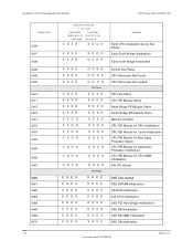
... DXE PCI Host Bridge initialization DXE NB initialization DXE NB SMM initialization DXE SB initialization Intel order number G13326-003 Revision 1.0 Appendix C: POST Code Diagnostic LED Decoder Intel®Server Board S1200BT TPS Progress Code 0x06 0x07 0x08 0x09 0x0E 0x0F 0x10 0x11 0x15 0x19 0x31 0x32 ...0x33 0x34 0x35 0x36 0x4F 0x60 0x61 0x62 0x63 0x68 0x69 0x6A 0x70 130 Diagnostic LED Decoder O = On, X=Off Upper ...
... DXE PCI Host Bridge initialization DXE NB initialization DXE NB SMM initialization DXE SB initialization Intel order number G13326-003 Revision 1.0 Appendix C: POST Code Diagnostic LED Decoder Intel®Server Board S1200BT TPS Progress Code 0x06 0x07 0x08 0x09 0x0E 0x0F 0x10 0x11 0x15 0x19 0x31 0x32 ...0x33 0x34 0x35 0x36 0x4F 0x60 0x61 0x62 0x63 0x68 0x69 0x6A 0x70 130 Diagnostic LED Decoder O = On, X=Off Upper ...

Product Specification
Page 143
Intel®Server Board S1200BT TPS Appendix C: POST Code Diagnostic LED Decoder Progress Code 0x71 0x72 0x78 0x79 0x90 0x91 0x92 0x93 0x94 0x95 0x96 0x97 0x98 0x99 0x9A 0x9B 0x9C 0x9D 0xA1 0xA2 0xA3 0xA4 0xA9 0xAB 0xAC 0xAD 0xAE 0xAF 0xB0 Diagnostic LED Decoder O = On, X=Off Upper Nibble Lower Nibble MSB 8h 4h 2h 1h... SETUP start DXE SETUP input wait DXE Ready to Boot DXE Legacy Boot DXE Exit Boot Services RT Set Virtual Address Map Begin Revision 1.0 131 Intel order number G13326-003
Intel®Server Board S1200BT TPS Appendix C: POST Code Diagnostic LED Decoder Progress Code 0x71 0x72 0x78 0x79 0x90 0x91 0x92 0x93 0x94 0x95 0x96 0x97 0x98 0x99 0x9A 0x9B 0x9C 0x9D 0xA1 0xA2 0xA3 0xA4 0xA9 0xAB 0xAC 0xAD 0xAE 0xAF 0xB0 Diagnostic LED Decoder O = On, X=Off Upper Nibble Lower Nibble MSB 8h 4h 2h 1h... SETUP start DXE SETUP input wait DXE Ready to Boot DXE Legacy Boot DXE Exit Boot Services RT Set Virtual Address Map Begin Revision 1.0 131 Intel order number G13326-003
Product Specification
Page 144
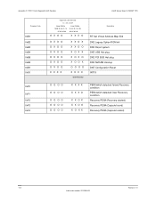
Appendix C: POST Code Diagnostic LED Decoder Intel®Server Board S1200BT TPS Progress Code 0xB1 0xB2 0xB3 0xB4 0xB5 0xB6 0xB7 0x00 0xF0 0xF1 0xF2 0xF3 0xF4 Diagnostic LED Decoder O = On, X=Off Upper Nibble Lower Nibble MSB 8h 4h 2h 1h 8h 4h 2h 1h LSB #7 #6 #5 #4 #3 #2 #1 #0 O X O O X X X O O X O O O X O O O X O O O X O O O X O O O X O O X X X X X X O X X X O O X O X X X O X O X O O X O O O O X X X X BIOS ... detected User Recovery condition Recovery PEIM (Recovery started) Recovery PEIM (Capsule found) Recovery PEIM (Capsule loaded) 132 Revision 1.0 Intel order number G13326-003
Appendix C: POST Code Diagnostic LED Decoder Intel®Server Board S1200BT TPS Progress Code 0xB1 0xB2 0xB3 0xB4 0xB5 0xB6 0xB7 0x00 0xF0 0xF1 0xF2 0xF3 0xF4 Diagnostic LED Decoder O = On, X=Off Upper Nibble Lower Nibble MSB 8h 4h 2h 1h 8h 4h 2h 1h LSB #7 #6 #5 #4 #3 #2 #1 #0 O X O O X X X O O X O O O X O O O X O O O X O O O X O O O X O O X X X X X X O X X X O O X O X X X O X O X O O X O O O O X X X X BIOS ... detected User Recovery condition Recovery PEIM (Recovery started) Recovery PEIM (Capsule found) Recovery PEIM (Capsule loaded) 132 Revision 1.0 Intel order number G13326-003


