
Design Guidelines
Page 4
... Procedures 51 5.3 Material and Recycling Requirements 52 5.4 Safety Requirements 52 5.5 Geometric Envelope for Intel Reference ATX Thermal Mechanical Design ......52 5.6 Reference Attach Mechanism 54 5.7 Socket and Voltage Regulation Cooling Strategy 55 6 Intel® Quiet System Technology (Intel® QST 57 6.1 Intel® Quiet System Technology Algorithm 57 6.1.1 Output Weighting Matrix 58 6.1.2 Proportional-Integral-Derivative (PID...
... Procedures 51 5.3 Material and Recycling Requirements 52 5.4 Safety Requirements 52 5.5 Geometric Envelope for Intel Reference ATX Thermal Mechanical Design ......52 5.6 Reference Attach Mechanism 54 5.7 Socket and Voltage Regulation Cooling Strategy 55 6 Intel® Quiet System Technology (Intel® QST 57 6.1 Intel® Quiet System Technology Algorithm 57 6.1.1 Output Weighting Matrix 58 6.1.2 Proportional-Integral-Derivative (PID...
Design Guidelines
Page 6
... 2. Example Thermal Profile 18 Figure 4. Locations for Heat Exchanger Fan Speed 56 Figure 21. Thermal Monitor 2 Frequency and Voltage Ordering 34 Figure 10. Random Vibration PSD 44 Figure 12. Reservoir Location 50 Figure 16. Heat Exchanger Fan Combination Foot ... Tape Installation 86 Figure 42. Solder Station Setup 89 Figure 47. Processor Case Temperature Measurement Location 17 Figure 3. LGA775 Socket Heatsink Loading Figures Figure 1. Preload Test Configuration 71 Figure 31. Intel® Quiet System Technology Platform Requirements 60 Figure 24. Locations for...
... 2. Example Thermal Profile 18 Figure 4. Locations for Heat Exchanger Fan Speed 56 Figure 21. Thermal Monitor 2 Frequency and Voltage Ordering 34 Figure 10. Random Vibration PSD 44 Figure 12. Reservoir Location 50 Figure 16. Heat Exchanger Fan Combination Foot ... Tape Installation 86 Figure 42. Solder Station Setup 89 Figure 47. Processor Case Temperature Measurement Location 17 Figure 3. LGA775 Socket Heatsink Loading Figures Figure 1. Preload Test Configuration 71 Figure 31. Intel® Quiet System Technology Platform Requirements 60 Figure 24. Locations for...
Design Guidelines
Page 31
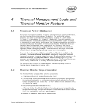
... A bi-directional signal (PROCHOT#) that it is available on user activation of voltage. Thermal and Mechanical Design Guidelines 31 By using more details on the processor. The relationship between frequency and power is aggressively pursuing low power design techniques. ...Thermal Monitor Implementation The Thermal Monitor consists of a processor, and Intel is generalized in processor frequency and performance. It provides a...
... A bi-directional signal (PROCHOT#) that it is available on user activation of voltage. Thermal and Mechanical Design Guidelines 31 By using more details on the processor. The relationship between frequency and power is aggressively pursuing low power design techniques. ...Thermal Monitor Implementation The Thermal Monitor consists of a processor, and Intel is generalized in processor frequency and performance. It provides a...
Design Guidelines
Page 32
... roughly parallels the thermal profile. The duty cycle is processor specific, and is asserted any register settings within specifications. As an input, assertion of voltage regulators (VR). One application is done by reducing the processor power consumption. By asserting PROCHOT# (pulledlow) or FORCEPR...is individually calibrated during manufacturing. Note: A thermal solution designed to lower the processor temperature by changing the duty cycle of the Thermal Monitor must be enabled for both cores. In the original implementation of thermal monitor this is the thermal protection of...
... roughly parallels the thermal profile. The duty cycle is processor specific, and is asserted any register settings within specifications. As an input, assertion of voltage regulators (VR). One application is done by reducing the processor power consumption. By asserting PROCHOT# (pulledlow) or FORCEPR...is individually calibrated during manufacturing. Note: A thermal solution designed to lower the processor temperature by changing the duty cycle of the Thermal Monitor must be enabled for both cores. In the original implementation of thermal monitor this is the thermal protection of...

Design Guidelines
Page 33
... is blocked. The second operating point consists of a specific operating frequency and voltage. The processor continues to the new frequency. Once the new operating frequency is engaged, the processor will transition to the new core operating voltage by dropping the bus-to-core multiplier to support Thermal Monitor 2. Each step will be one VID table entry...
... is blocked. The second operating point consists of a specific operating frequency and voltage. The processor continues to the new frequency. Once the new operating frequency is engaged, the processor will transition to the new core operating voltage by dropping the bus-to-core multiplier to support Thermal Monitor 2. Each step will be one VID table entry...

Design Guidelines
Page 34
... multiple PROCHOT# transitions around the trip point. Figure 9. PROCHOT# assertion. Thermal Monitor 2 Frequency and Voltage Ordering T TM2 Temperature f MAX f TM2 VID VID TM2 PROCHOT# Frequency VID Time 4.2.4 Operation and Configuration To maintain compatibility with previous generations of processors, which have no integrated thermal logic, the Thermal Control Circuit portion of the VID...
... multiple PROCHOT# transitions around the trip point. Figure 9. PROCHOT# assertion. Thermal Monitor 2 Frequency and Voltage Ordering T TM2 Temperature f MAX f TM2 VID VID TM2 PROCHOT# Frequency VID Time 4.2.4 Operation and Configuration To maintain compatibility with previous generations of processors, which have no integrated thermal logic, the Thermal Control Circuit portion of the VID...

Design Guidelines
Page 42
... Requirements Requirement Maximum Average fan current draw Fan start-up current draw Fan start-up current draw maximum duration Fan header voltage Tachometer output Tachometer output signal PWM signal input frequency PWM signal pull up in Section 5.2, the fan must be within ... (ball bearing, shaft, and tower assembly) must be demonstrated to passing the environmental reliability tests described in fan PWM signal current source PWM signal maximum voltage for logic low PWM compliant function Value 1.5 A 2.2 A 1.0 second 12 V ± 5% 2 pulse per revolution Open-collector (open-drain) 21 kHz...
... Requirements Requirement Maximum Average fan current draw Fan start-up current draw Fan start-up current draw maximum duration Fan header voltage Tachometer output Tachometer output signal PWM signal input frequency PWM signal pull up in Section 5.2, the fan must be within ... (ball bearing, shaft, and tower assembly) must be demonstrated to passing the environmental reliability tests described in fan PWM signal current source PWM signal maximum voltage for logic low PWM compliant function Value 1.5 A 2.2 A 1.0 second 12 V ± 5% 2 pulse per revolution Open-collector (open-drain) 21 kHz...

Design Guidelines
Page 43
Intel Thermal/Mechanical Reference Design Information 5.1.6 Pump Motor Performance The pump power requirements... Electrical Performance Requirements Requirement Maximum Average motor current draw Motor start-up current draw Motor header voltage Tachometer output Tachometer output signal Tachometer output signal current sink capability PWM signal input frequency PWM ...signal pull up in fan PWM signal current source PWM signal maximum voltage for logic low PWM compliant function Value 1.5 A 2.2 A 12 V ±5% 3 pulse per revolution Open...
Intel Thermal/Mechanical Reference Design Information 5.1.6 Pump Motor Performance The pump power requirements... Electrical Performance Requirements Requirement Maximum Average motor current draw Motor start-up current draw Motor header voltage Tachometer output Tachometer output signal Tachometer output signal current sink capability PWM signal input frequency PWM ...signal pull up in fan PWM signal current source PWM signal maximum voltage for logic low PWM compliant function Value 1.5 A 2.2 A 12 V ±5% 3 pulse per revolution Open...

Design Guidelines
Page 55
...exchanger design allows for air to be addressed when using a remote heat exchanger. Intel Thermal/Mechanical Reference Design Information 5.7 Socket and Voltage Regulation Cooling Strategy Consideration for processor cooling can remove the cooling air that eliminates the need and traditionally get from an... active heatsink directly attached to the processor IHS. The proximity of airflow to the voltage regulation components. Effectively the fan operating point increase is delivered to the VR and socket. ...
...exchanger design allows for air to be addressed when using a remote heat exchanger. Intel Thermal/Mechanical Reference Design Information 5.7 Socket and Voltage Regulation Cooling Strategy Consideration for processor cooling can remove the cooling air that eliminates the need and traditionally get from an... active heatsink directly attached to the processor IHS. The proximity of airflow to the voltage regulation components. Effectively the fan operating point increase is delivered to the VR and socket. ...

Design Guidelines
Page 60
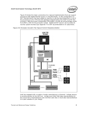
... System Technology Platform Requirements Processor Intel® (G)MCH MMEE DRAM DRAM Intel® ICH8 Controller Link FSC Control SPI SPI Flash SST Sensor Note: Simple Serial Transport (SST) is a single wire bus that is included in the ... To implement the board it must be configured as shown in Figure 23 and listed in the ICH8 to provide additional thermal and voltage sensing capability to provide board thermal data for the Intel QST Firmware • SST-based thermal sensors to the Manageability Engine (ME) 60 Thermal and Mechanical Design Guidelines
... System Technology Platform Requirements Processor Intel® (G)MCH MMEE DRAM DRAM Intel® ICH8 Controller Link FSC Control SPI SPI Flash SST Sensor Note: Simple Serial Transport (SST) is a single wire bus that is included in the ... To implement the board it must be configured as shown in Figure 23 and listed in the ICH8 to provide additional thermal and voltage sensing capability to provide board thermal data for the Intel QST Firmware • SST-based thermal sensors to the Manageability Engine (ME) 60 Thermal and Mechanical Design Guidelines
Design Guidelines
Page 61
...added to read the on-die thermal diode that can support processors with a number of major manufacturers of thermal / voltage sensors to monitor system thermal (see Appendix F for BTX recommendations for placement). Contact your Intel Field Sales representative for the current list of manufacturers and visit... can be added to provide devices for the SST bus. Intel® Quiet System Technology (Intel® QST) Figure 24 shows the major connections for a typical implementation that is in all of the processors in the 775-land LGA packages shipped before the Intel® Core™2 Duo...
...added to read the on-die thermal diode that can support processors with a number of major manufacturers of thermal / voltage sensors to monitor system thermal (see Appendix F for BTX recommendations for placement). Contact your Intel Field Sales representative for the current list of manufacturers and visit... can be added to provide devices for the SST bus. Intel® Quiet System Technology (Intel® QST) Figure 24 shows the major connections for a typical implementation that is in all of the processors in the 775-land LGA packages shipped before the Intel® Core™2 Duo...
Design Guidelines
Page 62
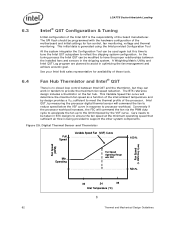
... Full Speed Variable Speed Fan (VSF) Curve 100 % Fan Speed (RPM) Fan Speed (% PWM Duty Cycle) Min. Intel QST, by measuring the processor digital thermal sensor will command the fan to reduce speed below the VSF curve in response to assist in BTX designs to ...fan control, fan monitoring, voltage and thermal monitoring. The SPI flash should be taken in optimizing the fan management and achieve acoustic goal. LGA775 Socket Heatsink Loading 6.3 Intel® QST Configuration & Tuning Initial configuration of the Intel QST is the responsibility of the processor. The BTX reference design ...
... Full Speed Variable Speed Fan (VSF) Curve 100 % Fan Speed (RPM) Fan Speed (% PWM Duty Cycle) Min. Intel QST, by measuring the processor digital thermal sensor will command the fan to reduce speed below the VSF curve in response to assist in BTX designs to ...fan control, fan monitoring, voltage and thermal monitoring. The SPI flash should be taken in optimizing the fan management and achieve acoustic goal. LGA775 Socket Heatsink Loading 6.3 Intel® QST Configuration & Tuning Initial configuration of the Intel QST is the responsibility of the processor. The BTX reference design ...

Design Guidelines
Page 98
... Controlled Fans; Figure 57. Operating 30 38 Fan Inlet Temperature (°C) E.1.2 Minimum Fan Speed Set Point The final aspect of the design, such as the processor voltage regulator, or by the external fan speed control. • Type B: The fan will run at 0% PWM duty cycle. • Type C: The fan will be programmed...
... Controlled Fans; Figure 57. Operating 30 38 Fan Inlet Temperature (°C) E.1.2 Minimum Fan Speed Set Point The final aspect of the design, such as the processor voltage regulator, or by the external fan speed control. • Type B: The fan will run at 0% PWM duty cycle. • Type C: The fan will be programmed...

Design Guidelines
Page 102
...low power state to use with the ATX Boxed Processor enabled reference solution a TRANGE value of 7 °C is recommended. This is the fan speed for additional discussion on • Acoustic target at system idle • Voltage regulator cooling For a motherboard design intending to ...TDP workloads without having TSENSOR above TCONTROL is recommended. For BTX Boxed Processor enabled reference solutions TRANGE value of 10°C is expected for ...
...low power state to use with the ATX Boxed Processor enabled reference solution a TRANGE value of 7 °C is recommended. This is the fan speed for additional discussion on • Acoustic target at system idle • Voltage regulator cooling For a motherboard design intending to ...TDP workloads without having TSENSOR above TCONTROL is recommended. For BTX Boxed Processor enabled reference solutions TRANGE value of 10°C is expected for ...