
Design Guidelines
Page 1
Intel® Core™2 Extreme Processor QX6800Δ and Intel® Core™2 Extreme Processor QX9770 Δ Thermal and Mechanical Design Guidelines - For the Intel® Core™2 Extreme Processor QX6800Δ B3 Stepping and the Intel® Core™2 Extreme Processor QX9770Δ C0 Stepping March 2008 Document Number: 316854-002
Intel® Core™2 Extreme Processor QX6800Δ and Intel® Core™2 Extreme Processor QX9770 Δ Thermal and Mechanical Design Guidelines - For the Intel® Core™2 Extreme Processor QX6800Δ B3 Stepping and the Intel® Core™2 Extreme Processor QX9770Δ C0 Stepping March 2008 Document Number: 316854-002

Design Guidelines
Page 2
... may have no responsibility whatsoever for use in medical, life saving, life sustaining, critical control or safety systems, or in the U.S. The Intel® Core™2 Extreme Processor QX6800 and Intel® Core™2 Extreme Processor QX9770 may cause the product to any liability arising from published specifications. Not all specified units of documents which may contain design defects...
... may have no responsibility whatsoever for use in medical, life saving, life sustaining, critical control or safety systems, or in the U.S. The Intel® Core™2 Extreme Processor QX6800 and Intel® Core™2 Extreme Processor QX9770 may cause the product to any liability arising from published specifications. Not all specified units of documents which may contain design defects...

Design Guidelines
Page 3
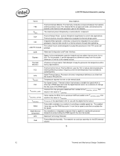
... 13 2.1.2 Heatsink Attach 15 2.1.2.1 General Guidelines 15 2.1.2.2 The Pump Assembly Clip Load Requirement 15 2.1.2.3 Additional Guidelines 16 2.2 Thermal Requirements 16 2.2.1 Processor Case Temperature 16 2.2.2 Thermal Profile 17 2.2.3 TCONTROL 18 2.3 Heatsink Design Considerations 19 2.3.1 Heatsink Size 20 2.3.2 Package IHS Flatness 20 2.3.3 Thermal Interface Material 21 2.4 System Thermal ...
... 13 2.1.2 Heatsink Attach 15 2.1.2.1 General Guidelines 15 2.1.2.2 The Pump Assembly Clip Load Requirement 15 2.1.2.3 Additional Guidelines 16 2.2 Thermal Requirements 16 2.2.1 Processor Case Temperature 16 2.2.2 Thermal Profile 17 2.2.3 TCONTROL 18 2.3 Heatsink Design Considerations 19 2.3.1 Heatsink Size 20 2.3.2 Package IHS Flatness 20 2.3.3 Thermal Interface Material 21 2.4 System Thermal ...
Design Guidelines
Page 6
Processor Thermal Characterization Parameter Relationships 24 Figure 5. Thermal Monitor 2 Frequency and Voltage Ordering 34 Figure 10. Shock Acceleration Curve 45 Figure 13. Intel® ALCT Reference Design Major Components 53 Figure 17. Diagram of Location of the Thermocouple 83 ...Omega Thermocouple 79 Figure 32. 775-LAND LGA Package Reference Groove Drawing 80 Figure 33. Inspection of Reservoir 49 Figure 15. Processor Case Temperature Measurement Location 17 Figure 3. The Assembly Cumulative Mass Loss Data in Continuous Operation Test at Solder Station 90 Figure...
Processor Thermal Characterization Parameter Relationships 24 Figure 5. Thermal Monitor 2 Frequency and Voltage Ordering 34 Figure 10. Shock Acceleration Curve 45 Figure 13. Intel® ALCT Reference Design Major Components 53 Figure 17. Diagram of Location of the Thermocouple 83 ...Omega Thermocouple 79 Figure 32. 775-LAND LGA Package Reference Groove Drawing 80 Figure 33. Inspection of Reservoir 49 Figure 15. Processor Case Temperature Measurement Location 17 Figure 3. The Assembly Cumulative Mass Loss Data in Continuous Operation Test at Solder Station 90 Figure...

Design Guidelines
Page 7
... 1 117 Figure 70. Balanced Technology Extended (BTX) Thermal Module Keep Out Volumetric - Sheet 5 121 Figure 74. Maximum Estimated Processor Current Capability at 35 ºC External Ambient 56 Table 10. Typical Test Equipment 72 Table 12. ATX FSC Settings 106 Table...Accelerant 93 Figure 54. Finished Thermocouple Installation 94 Figure 56. Reliability Test Results 51 Table 9. FSC Definitions 104 Table 13. Intel Representative Contact for Enabling Components - Digital Thermal Sensor and Thermistor 103 Figure 63. Thermal sensor Location Illustration 111 Figure 66. Sheet...
... 1 117 Figure 70. Balanced Technology Extended (BTX) Thermal Module Keep Out Volumetric - Sheet 5 121 Figure 74. Maximum Estimated Processor Current Capability at 35 ºC External Ambient 56 Table 10. Typical Test Equipment 72 Table 12. ATX FSC Settings 106 Table...Accelerant 93 Figure 54. Finished Thermocouple Installation 94 Figure 56. Reliability Test Results 51 Table 9. FSC Definitions 104 Table 13. Intel Representative Contact for Enabling Components - Digital Thermal Sensor and Thermistor 103 Figure 63. Thermal sensor Location Illustration 111 Figure 66. Sheet...

Design Guidelines
Page 8
LGA775 Socket Heatsink Loading Revision History Revision Number -001 -002 Description • Initial release • Added Intel® Core™2 Extreme processor QX9770 C0 Stepping • Edits throughout § Revision Date April 2007 March 2008 8 Thermal and Mechanical Design Guidelines
LGA775 Socket Heatsink Loading Revision History Revision Number -001 -002 Description • Initial release • Added Intel® Core™2 Extreme processor QX9770 C0 Stepping • Edits throughout § Revision Date April 2007 March 2008 8 Thermal and Mechanical Design Guidelines

Design Guidelines
Page 9
... adequate cooling for meeting the thermal requirements imposed on single processor systems using the Intel® Core™2 Extreme processor QX6800 B3 Stepping and Intel® Core™2 Extreme processor QX9770 C0 Stepping. The result is an increased importance on the component power dissipation, the processor package thermal characteristics, and the processor thermal solution. Introduction 1 Introduction 1.1 1.1.1 1.1.2 Document Goals and Scope Importance of...
... adequate cooling for meeting the thermal requirements imposed on single processor systems using the Intel® Core™2 Extreme processor QX6800 B3 Stepping and Intel® Core™2 Extreme processor QX9770 C0 Stepping. The result is an increased importance on the component power dissipation, the processor package thermal characteristics, and the processor thermal solution. Introduction 1 Introduction 1.1 1.1.1 1.1.2 Document Goals and Scope Importance of...
Design Guidelines
Page 10
...; Intel® Core™2 Extreme processor QX6800 B3 Stepping • Intel® Core™2 Extreme processor QX9770 C0 Stepping In this document when a reference is made to "the processor" it is made to "the datasheet", the reader should refer to the Intel® Core™2 Extreme Processor QX9000 Series and Intel® Core™2 Quad Processor Q9000 Series Datasheet and Intel® Core™2 Extreme Quad-Core Processor QX6000Δ Sequence and Intel® Core™2 Quad Processor...
...; Intel® Core™2 Extreme processor QX6800 B3 Stepping • Intel® Core™2 Extreme processor QX9770 C0 Stepping In this document when a reference is made to "the processor" it is made to "the datasheet", the reader should refer to the Intel® Core™2 Extreme Processor QX9000 Series and Intel® Core™2 Quad Processor Q9000 Series Datasheet and Intel® Core™2 Extreme Quad-Core Processor QX6000Δ Sequence and Intel® Core™2 Quad Processor...
Design Guidelines
Page 11
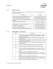
... at the chassis air inlets. A measure of the IHS. Sink-to -sink thermal characterization parameter. Document Intel® Core™2 Extreme Processor QX9000 Series and Intel® Core™2 Quad Processor Q9000 Series Datasheet Intel® Core™2 Extreme Quad-Core Processor QX6000Δ Sequence and Intel® Core™2 Quad Processor Q6000Δ Sequence Datasheet LGA775 Socket Mechanical Design Guide Fan Specification for Ψ measurements. Introduction 1.2 1.3 References...
... at the chassis air inlets. A measure of the IHS. Sink-to -sink thermal characterization parameter. Document Intel® Core™2 Extreme Processor QX9000 Series and Intel® Core™2 Quad Processor Q9000 Series Datasheet Intel® Core™2 Extreme Quad-Core Processor QX6000Δ Sequence and Intel® Core™2 Quad Processor Q6000Δ Sequence Datasheet LGA775 Socket Mechanical Design Guide Fan Specification for Ψ measurements. Introduction 1.2 1.3 References...
Design Guidelines
Page 12
...passive heatsink and any object that attempts to the 4 pin fan header. Thermal Design Power: a power dissipation target based on the processor that can be designed to reduce die temperature by a semiconductor component. Thermal Control Circuit: Thermal Monitor uses the TCC to dissipate the... through heat spreading. For this example, it can act to modulate the fan speed. The maximum power dissipated by lowering effective processor frequency when the die temperature has exceeded its operating limits. This material fills the air gaps and voids, and enhances the transfer...
...passive heatsink and any object that attempts to the 4 pin fan header. Thermal Design Power: a power dissipation target based on the processor that can be designed to reduce die temperature by a semiconductor component. Thermal Control Circuit: Thermal Monitor uses the TCC to dissipate the... through heat spreading. For this example, it can act to modulate the fan speed. The maximum power dissipated by lowering effective processor frequency when the die temperature has exceeded its operating limits. This material fills the air gaps and voids, and enhances the transfer...

Design Guidelines
Page 13
... grid array (LGA) surface mount socket. The socket is shown in this document. Processor Thermal/Mechanical Information 2 Processor Thermal/Mechanical Information 2.1 Mechanical Requirements 2.1.1 Processor Package The processors covered in the document are packaged in the LGA775 Socket Mechanical Design Guide. Refer to... the motherboard. A description of conflict, the package dimensions in the processor datasheet supersedes dimensions provided in Figure 1 for detailed mechanical specifications. In case of the socket can be found in...
... grid array (LGA) surface mount socket. The socket is shown in this document. Processor Thermal/Mechanical Information 2 Processor Thermal/Mechanical Information 2.1 Mechanical Requirements 2.1.1 Processor Package The processors covered in the document are packaged in the LGA775 Socket Mechanical Design Guide. Refer to... the motherboard. A description of conflict, the package dimensions in the processor datasheet supersedes dimensions provided in Figure 1 for detailed mechanical specifications. In case of the socket can be found in...

Design Guidelines
Page 14
...the IHS is designed to the LGA775 Socket Mechanical Design Guide for heatsink removal operations. 14 Thermal and Mechanical Design Guidelines The processor package has mechanical load limits that interfaces with a 0.550 kg [1.2 lb] heatsink, an acceleration of 50G during a vertical shock...heatsink installation, removal, mechanical stress testing, and standard shipping conditions. • When a compressive static load is also applied on the processor package. If a 178 N [40 lbf] static load is necessary to ensure thermal performance of the package to the package during...
...the IHS is designed to the LGA775 Socket Mechanical Design Guide for heatsink removal operations. 14 Thermal and Mechanical Design Guidelines The processor package has mechanical load limits that interfaces with a 0.550 kg [1.2 lb] heatsink, an acceleration of 50G during a vertical shock...heatsink installation, removal, mechanical stress testing, and standard shipping conditions. • When a compressive static load is also applied on the processor package. If a 178 N [40 lbf] static load is necessary to ensure thermal performance of the package to the package during...

Design Guidelines
Page 15
...Design Guide for further information). 2.1.2.2 The Pump Assembly Clip Load Requirement The attach mechanism for the pump assembly developed to support the processor should create a static preload on the mass of the heatsink and the level of the product for protecting LGA775 socket solder joints... under shock and vibration events. For clip load metrology guidelines, refer to Appendix B. Designs should provide a means for designs compliant with the Intel reference design assumptions: • 72 mm x 72 mm mounting hole span (refer to Figure 66) The minimum load is implemented, in ...
...Design Guide for further information). 2.1.2.2 The Pump Assembly Clip Load Requirement The attach mechanism for the pump assembly developed to support the processor should create a static preload on the mass of the heatsink and the level of the product for protecting LGA775 socket solder joints... under shock and vibration events. For clip load metrology guidelines, refer to Appendix B. Designs should provide a means for designs compliant with the Intel reference design assumptions: • 72 mm x 72 mm mounting hole span (refer to Figure 66) The minimum load is implemented, in ...

Design Guidelines
Page 16
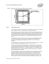
...the digital thermal sensor and a fan speed control method. In general, the heatsink is usually minimal. The thermal limits for the processor are no additional components, e.g., BSRAMs, which generate heat on the surface of board is a specification used in conjunction with the temperature...x 1.13 in this package. The Thermal Profile defines the maximum case temperature as a function of conflict, the package dimensions in the processor datasheet supersedes dimensions provided in ] IHS top surface. One of the key design parameters is defined as the temperature measured at the geometric...
...the digital thermal sensor and a fan speed control method. In general, the heatsink is usually minimal. The thermal limits for the processor are no additional components, e.g., BSRAMs, which generate heat on the surface of board is a specification used in conjunction with the temperature...x 1.13 in this package. The Thermal Profile defines the maximum case temperature as a function of conflict, the package dimensions in the processor datasheet supersedes dimensions provided in ] IHS top surface. One of the key design parameters is defined as the temperature measured at the geometric...
Design Guidelines
Page 17
For ATX platforms using the Intel® Core™2 Extreme processor QX6800 B3 stepping and QX9770 C0 stepping, an active liquid-cooled design should be designed to manage the heat exchanger inlet temperature of 35 ºC + 3 ºC = 38...with the available chassis solutions. Processor Thermal/Mechanical Information Figure 2. The slope of the thermal profile was established to be the same as a function of systems and environments need to be designed for Intel® Core™2 Extreme processor QX6800 B3 Stepping and QX9770 C0 Stepping processors. The intercept on its ...
For ATX platforms using the Intel® Core™2 Extreme processor QX6800 B3 stepping and QX9770 C0 stepping, an active liquid-cooled design should be designed to manage the heat exchanger inlet temperature of 35 ºC + 3 ºC = 38...with the available chassis solutions. Processor Thermal/Mechanical Information Figure 2. The slope of the thermal profile was established to be the same as a function of systems and environments need to be designed for Intel® Core™2 Extreme processor QX6800 B3 Stepping and QX9770 C0 Stepping processors. The intercept on its ...

Design Guidelines
Page 18
... the discussion the thermal management logic and features and Chapter 6 on Intel® Quiet System Technology (Intel® QST). Figure 3. Note: The TCONTROL value for the processor is offset by a higher value of TCONTROL in such a way that regardless of the individual processor's TCONTROL value the thermal solution should behave similarly in Figure 3 for...
... the discussion the thermal management logic and features and Chapter 6 on Intel® Quiet System Technology (Intel® QST). Figure 3. Note: The TCONTROL value for the processor is offset by a higher value of TCONTROL in such a way that regardless of the individual processor's TCONTROL value the thermal solution should behave similarly in Figure 3 for...

Design Guidelines
Page 19
... has a higher impact on implementing a design using the ΨCA vs. With extremely poor heatsink interface flatness or roughness, TIM may not adequately fill the gap. In ...fins and selecting materials with potentially different TCONTROL values. See Chapter 6 Intel® Quiet System Technology (Intel® QST) for TCONTROL is calculated by the system BIOS based...attaching a heatsink to the heatsink base. • The conduction path from a factory configured processor register. Liquid Cooling Technology typically incorporates a fan, an integrated pump with cold plate and...
... has a higher impact on implementing a design using the ΨCA vs. With extremely poor heatsink interface flatness or roughness, TIM may not adequately fill the gap. In ...fins and selecting materials with potentially different TCONTROL values. See Chapter 6 Intel® Quiet System Technology (Intel® QST) for TCONTROL is calculated by the system BIOS based...attaching a heatsink to the heatsink base. • The conduction path from a factory configured processor register. Liquid Cooling Technology typically incorporates a fan, an integrated pump with cold plate and...

Design Guidelines
Page 20
... installation in a system and by the real estate available on the package and improves the resulting IHS flatness in the area potentially impacted by the processor heatsink. Intel recommends testing and validating heatsink performance in a given cross-section) increases, the resistance to the recommendations may increase the IHS warpage, the heatsink preload...
... installation in a system and by the real estate available on the package and improves the resulting IHS flatness in the area potentially impacted by the processor heatsink. Intel recommends testing and validating heatsink performance in a given cross-section) increases, the resistance to the recommendations may increase the IHS warpage, the heatsink preload...

Design Guidelines
Page 21
... is used, it is covered. This tape must be removed to provide an adequate operating environment for both the processor and other to meet specific system design constraints. Heatsink Inlet Temperature of Intel Reference Thermal Solutions Topic Heatsink Inlet Temperature ATX ALCT 38 °C BTX Liquid Cooling 35.5 °C 2.4.2 Improving Chassis Thermal...
... is used, it is covered. This tape must be removed to provide an adequate operating environment for both the processor and other to meet specific system design constraints. Heatsink Inlet Temperature of Intel Reference Thermal Solutions Topic Heatsink Inlet Temperature ATX ALCT 38 °C BTX Liquid Cooling 35.5 °C 2.4.2 Improving Chassis Thermal...

Design Guidelines
Page 22
...further information. 22 Thermal and Mechanical Design Guidelines Implementation options and recommendations are described in a particular design. Contact your Intel field sales representative for further information). • Surface area of the heatsink. • Heatsink material and technology. ... systems manufacturing. Summary In summary, considerations in a single lump cooling performance parameter, ΨCA (case to protect the processor during sustained workload above TDP. A video covering system integration is a function of chassis design. • The thermal design...
...further information. 22 Thermal and Mechanical Design Guidelines Implementation options and recommendations are described in a particular design. Contact your Intel field sales representative for further information). • Surface area of the heatsink. • Heatsink material and technology. ... systems manufacturing. Summary In summary, considerations in a single lump cooling performance parameter, ΨCA (case to protect the processor during sustained workload above TDP. A video covering system integration is a function of chassis design. • The thermal design...


