
Design Guidelines
Page 4
...11 THERMTRIP# Signal 36 Cooling System Failure Warning 36 Digital Thermal Sensor 37 Platform Environmental Control Interface (PECI 38 5 Intel Thermal/Mechanical Reference Design Information 39 5.1 Validation Results for the ATX Reference Design 39 5.1.1 5.1.2 5.1.3 5.1.4 5.1.5 5.1.6... Considerations 63 A.2 Metric for Heatsink Preload for ATX/uATX Designs Non-Compliant with Intel® Reference Design 64 A.2.1 Heatsink Preload Requirement Limitations 64 A.2.2 Motherboard Deflection Metric Definition 64 A.2.3 Board Deflection Limits 66 A.2.4 Board Deflection Metric Implementation ...
...11 THERMTRIP# Signal 36 Cooling System Failure Warning 36 Digital Thermal Sensor 37 Platform Environmental Control Interface (PECI 38 5 Intel Thermal/Mechanical Reference Design Information 39 5.1 Validation Results for the ATX Reference Design 39 5.1.1 5.1.2 5.1.3 5.1.4 5.1.5 5.1.6... Considerations 63 A.2 Metric for Heatsink Preload for ATX/uATX Designs Non-Compliant with Intel® Reference Design 64 A.2.1 Heatsink Preload Requirement Limitations 64 A.2.2 Motherboard Deflection Metric Definition 64 A.2.3 Board Deflection Limits 66 A.2.4 Board Deflection Metric Implementation ...
Design Guidelines
Page 6
... and Voltage Ordering 34 Figure 10. TCONTROL for Measuring Local Ambient Temperature, Liquid-Cooling Heat Exchanger 28 Figure 7. Intel® ALCT Reference Design Major Components 53 Figure 17. Bending the Tip of Heat Exchanger VR and Socket Airflow ... Bottom View ...70 Figure 29. IHS Groove Orientation Relative to Motherboard Interface 54 Figure 19. LGA775 Socket Heatsink Loading Figures Figure 1. Processor Case Temperature Measurement Location 17 Figure 3. Processor Thermal Characterization Parameter Relationships 24 Figure 5. Locations for Heat Exchanger ...
... and Voltage Ordering 34 Figure 10. TCONTROL for Measuring Local Ambient Temperature, Liquid-Cooling Heat Exchanger 28 Figure 7. Intel® ALCT Reference Design Major Components 53 Figure 17. Bending the Tip of Heat Exchanger VR and Socket Airflow ... Bottom View ...70 Figure 29. IHS Groove Orientation Relative to Motherboard Interface 54 Figure 19. LGA775 Socket Heatsink Loading Figures Figure 1. Processor Case Temperature Measurement Location 17 Figure 3. Processor Thermal Characterization Parameter Relationships 24 Figure 5. Locations for Heat Exchanger ...

Design Guidelines
Page 7
...Control Settings 106 Table 15. System Airflow Illustration with Adhesive 93 Figure 53. Intel Liquid Cooled Reference Design Performance (ALCT 40 Table 3. Maximum Estimated Processor Current Capability at 35 ºC External Ambient 56 Table 10. Thermistor Set ...- Sheet 3 119 Figure 72. The Weekly Loss Rate of Intel Reference Thermal Solutions 21 Table 2. Reliability Test Results 51 Table 9. Intel Representative Contact for Enabling Components - ATX/µATX Motherboard Keep-out Footprint Definition and Height Restrictions for Enabling Components - Sheet...
...Control Settings 106 Table 15. System Airflow Illustration with Adhesive 93 Figure 53. Intel Liquid Cooled Reference Design Performance (ALCT 40 Table 3. Maximum Estimated Processor Current Capability at 35 ºC External Ambient 56 Table 10. Thermistor Set ...- Sheet 3 119 Figure 72. The Weekly Loss Rate of Intel Reference Thermal Solutions 21 Table 2. Reliability Test Results 51 Table 9. Intel Representative Contact for Enabling Components - ATX/µATX Motherboard Keep-out Footprint Definition and Height Restrictions for Enabling Components - Sheet...

Design Guidelines
Page 13
...to interface with solder balls for illustration only. Refer to the datasheet for further information. Refer to the processor datasheet for detailed mechanical specifications. Figure 1. The socket contains 775 contacts arrayed about a cavity in the center of conflict... is shown in Figure 1 for surface mounting to the motherboard through a land grid array (LGA) surface mount socket. Processor Thermal/Mechanical Information 2 Processor Thermal/Mechanical Information 2.1 Mechanical Requirements 2.1.1 Processor Package The processors covered in the document are packaged in a 775-Land ...
...to interface with solder balls for illustration only. Refer to the datasheet for further information. Refer to the processor datasheet for detailed mechanical specifications. Figure 1. The socket contains 775 contacts arrayed about a cavity in the center of conflict... is shown in Figure 1 for surface mounting to the motherboard through a land grid array (LGA) surface mount socket. Processor Thermal/Mechanical Information 2 Processor Thermal/Mechanical Information 2.1 Mechanical Requirements 2.1.1 Processor Package The processors covered in the document are packaged in a 775-Land ...

Design Guidelines
Page 15
...designing the heatsink attach mechanism. For clip load metrology guidelines, refer to the motherboard. TIMs, such as thermal greases, are very sensitive to protect against fatigue... account potential load degradation from the reference design assumptions, refer to support the processor should consider a possible decrease in temperature cycling. Thermal and Mechanical Design Guidelines ... Load Requirement The attach mechanism for the pump assembly developed to Appendix A. The Intel ALCT reference design attach mechanism described in retention components. • Ensuring system electrical...
...designing the heatsink attach mechanism. For clip load metrology guidelines, refer to the motherboard. TIMs, such as thermal greases, are very sensitive to protect against fatigue... account potential load degradation from the reference design assumptions, refer to support the processor should consider a possible decrease in temperature cycling. Thermal and Mechanical Design Guidelines ... Load Requirement The attach mechanism for the pump assembly developed to Appendix A. The Intel ALCT reference design attach mechanism described in retention components. • Ensuring system electrical...

Design Guidelines
Page 16
...by the heatsink attach mechanism must comply with the motherboard surface during installation and actuation to avoid scratching the motherboard. 2.2 Thermal Requirements Refer to the datasheet for the processor thermal specifications. TCONTROL is dissipated through the processor package substrate and into the chassis. • ...from: ⎯ The height of the IHS. This data is the height of the top surface of the processor IHS above the motherboard after the motherboard has been installed into the socket is assumed to be installed after reflow, given in the LGA775 Socket Mechanical...
...by the heatsink attach mechanism must comply with the motherboard surface during installation and actuation to avoid scratching the motherboard. 2.2 Thermal Requirements Refer to the datasheet for the processor thermal specifications. TCONTROL is dissipated through the processor package substrate and into the chassis. • ...from: ⎯ The height of the IHS. This data is the height of the top surface of the processor IHS above the motherboard after the motherboard has been installed into the socket is assumed to be installed after reflow, given in the LGA775 Socket Mechanical...

Design Guidelines
Page 20
... Guidelines As the heatsink fin density (the number of the heatsink is generally not entirely available for the motherboard form factor of other design considerations (air duct, etc.). Intel recommends testing and validating heatsink performance in full mechanical enabling configuration to capture any impact of the airflow in... instead of the heatsink must take into account airflow considerations (for fan performance for installation in a system and by the processor heatsink. Typically, passive heatsinks see lower air speed. Heatsink Size The size of fins in the chassis.
... Guidelines As the heatsink fin density (the number of the heatsink is generally not entirely available for the motherboard form factor of other design considerations (air duct, etc.). Intel recommends testing and validating heatsink performance in full mechanical enabling configuration to capture any impact of the airflow in... instead of the heatsink must take into account airflow considerations (for fan performance for installation in a system and by the processor heatsink. Typically, passive heatsinks see lower air speed. Heatsink Size The size of fins in the chassis.

Design Guidelines
Page 26
...3 mm to 8 mm [0.1 to 0.3 in] above the test motherboard surface can be useful, and usually ensures more realistic airflow, the motherboard should be easily translated to variances in the chassis around the processor during system thermal testing. The thermocouples should be assessed using a thermal...bench to characterize an active heatsink can help evaluate the potential impact of the thermal solution on real processors and on fully integrated systems. The Intel maximum power application enables steady power dissipation on the case temperature. For even more uniform temperatures at...
...3 mm to 8 mm [0.1 to 0.3 in] above the test motherboard surface can be useful, and usually ensures more realistic airflow, the motherboard should be easily translated to variances in the chassis around the processor during system thermal testing. The thermocouples should be assessed using a thermal...bench to characterize an active heatsink can help evaluate the potential impact of the thermal solution on real processors and on fully integrated systems. The Intel maximum power application enables steady power dissipation on the case temperature. For even more uniform temperatures at...

Design Guidelines
Page 27
When measuring TA in a chassis with a live motherboard, add-in cards, and other system components, it is meant to minimize the effect of the temperature sensor used by the fan to check its ... in these conditions, it may be done in a thermal chamber to 1.0 in] away from operating at room temperature, the fan regulation prevents the heatsink from processor and heatsink as previously described, half way between the fan hub and the fan housing. Thermal Metrology heatsink. Locations for Measuring Local Ambient Temperature, Active...
When measuring TA in a chassis with a live motherboard, add-in cards, and other system components, it is meant to minimize the effect of the temperature sensor used by the fan to check its ... in these conditions, it may be done in a thermal chamber to 1.0 in] away from operating at room temperature, the fan regulation prevents the heatsink from processor and heatsink as previously described, half way between the fan hub and the fan housing. Thermal Metrology heatsink. Locations for Measuring Local Ambient Temperature, Active...

Design Guidelines
Page 39
...pump and cold-plate (or chiller) and a remote heat exchanger with an attached fan. The unit is called the Intel Advanced Liquid Cooling Technology Reference Design (Intel ALCT Reference Design). The major ALCT components are sealed for the impeller. There are no dynamic seals in turn act as...reservoir the units are provided Figure 16. The seal is used in a double involute and returned to the pump with the reference ATX motherboard keep -out and the heat exchanger is then accelerated through the cold plate fins. Through careful selection of materials and the unique heat ...
...pump and cold-plate (or chiller) and a remote heat exchanger with an attached fan. The unit is called the Intel Advanced Liquid Cooling Technology Reference Design (Intel ALCT Reference Design). The major ALCT components are sealed for the impeller. There are no dynamic seals in turn act as...reservoir the units are provided Figure 16. The seal is used in a double involute and returned to the pump with the reference ATX motherboard keep -out and the heat exchanger is then accelerated through the cold plate fins. Through careful selection of materials and the unique heat ...

Design Guidelines
Page 45
... e r 30 a t 20 i o n 10 (g) 0 0 2 4 6 8 10 12 Time (m illiseconds) 5.2.1.2.1 Recommended Test Sequence Each test sequence should be preconditioned for + and - The stress test should start with components (i.e., motherboard, heatsink assembly, etc.) that have never been previously submitted to any reliability testing. Thermal and Mechanical Design Guidelines 45 The pre-conditioning is intended to...
... e r 30 a t 20 i o n 10 (g) 0 0 2 4 6 8 10 12 Time (m illiseconds) 5.2.1.2.1 Recommended Test Sequence Each test sequence should be preconditioned for + and - The stress test should start with components (i.e., motherboard, heatsink assembly, etc.) that have never been previously submitted to any reliability testing. Thermal and Mechanical Design Guidelines 45 The pre-conditioning is intended to...

Design Guidelines
Page 46
... ALCT and the sensitivity of reliability to its attach mechanism. 4. No visible gap between the heatsink base and processor IHS. Successful BIOS/Processor/memory test of the reliability testing and their impact on thermal resistance pump motor performance and on pump integrity are...tubing as well as clip and motherboard fasteners). 2. The objective of the reliability testing of the vapor transmission loss. The reliability testing and results are summarized. The results of post-test samples. 7. Thermal Test Vehicle (refer to the processor package. 6. No significant physical...
... ALCT and the sensitivity of reliability to its attach mechanism. 4. No visible gap between the heatsink base and processor IHS. Successful BIOS/Processor/memory test of the reliability testing and their impact on thermal resistance pump motor performance and on pump integrity are...tubing as well as clip and motherboard fasteners). 2. The objective of the reliability testing of the vapor transmission loss. The reliability testing and results are summarized. The results of post-test samples. 7. Thermal Test Vehicle (refer to the processor package. 6. No significant physical...

Design Guidelines
Page 51
...after environmental stresses, with the thermal mechanical enabling components assembled. Testing setup should include the following components, properly assembled and/or connected: • Appropriate system motherboard • Processor • All enabling components, including socket and thermal solution parts • Power supply • Disk drive • Video card • DIMM &#... not been exposed to ensure proper operation of tests prior to the test being considered. Thermal and Mechanical Design Guidelines 51 Intel Thermal/Mechanical Reference Design Information Table 8.
...after environmental stresses, with the thermal mechanical enabling components assembled. Testing setup should include the following components, properly assembled and/or connected: • Appropriate system motherboard • Processor • All enabling components, including socket and thermal solution parts • Power supply • Disk drive • Video card • DIMM &#... not been exposed to ensure proper operation of tests prior to the test being considered. Thermal and Mechanical Design Guidelines 51 Intel Thermal/Mechanical Reference Design Information Table 8.

Design Guidelines
Page 52
... components must have deformation or degradation in the ATX Specification revision 2.2 and the microATX Motherboard Interface Specification revision 1.2 found at the system level. Geometric Envelope for Intel Reference ATX Thermal Mechanical Design Figure 66, Figure 67, and Figure 68 in particular ...Certification. Material used shall not have CSA certification. • All components (in Appendix G gives detailed reference ATX/μATX motherboard keep-out information for the flexible hoses which transit the area to the heat exchanger which contain organic fillers of non-resistant ...
... components must have deformation or degradation in the ATX Specification revision 2.2 and the microATX Motherboard Interface Specification revision 1.2 found at the system level. Geometric Envelope for Intel Reference ATX Thermal Mechanical Design Figure 66, Figure 67, and Figure 68 in particular ...Certification. Material used shall not have CSA certification. • All components (in Appendix G gives detailed reference ATX/μATX motherboard keep-out information for the flexible hoses which transit the area to the heat exchanger which contain organic fillers of non-resistant ...

Design Guidelines
Page 54
... pump is attached to the pump is defined in Figure 74. The range of recommended positions of the heat exchanger relative to the motherboard through the use of the board into the chassis the pump and upper structure are secured to the... motherboard and backside stiffener with two screws. Prior to Motherboard Interface 54 Thermal and Mechanical Design Guidelines Structure to motherboard installation in the accessory kit. After installation of a backside stiffener plate. Once installed these screws...
... pump is attached to the pump is defined in Figure 74. The range of recommended positions of the heat exchanger relative to the motherboard through the use of the board into the chassis the pump and upper structure are secured to the... motherboard and backside stiffener with two screws. Prior to Motherboard Interface 54 Thermal and Mechanical Design Guidelines Structure to motherboard installation in the accessory kit. After installation of a backside stiffener plate. Once installed these screws...

Design Guidelines
Page 55
The use of a remote heat exchanger for processor cooling can remove the cooling air that is integrated into the... how a small gap or exit between the fan's pressure side and the heat exchanger inlet that the motherboard components around the socket need for additional fan(s) on the rear panel of the ATX miniTower /Tower allows... point increase is delivered to the VR and socket. Figure 19. Thermal and Mechanical Design Guidelines 55 Intel Thermal/Mechanical Reference Design Information 5.7 Socket and Voltage Regulation Cooling Strategy Consideration for the cooling of power delivery...
The use of a remote heat exchanger for processor cooling can remove the cooling air that is integrated into the... how a small gap or exit between the fan's pressure side and the heat exchanger inlet that the motherboard components around the socket need for additional fan(s) on the rear panel of the ATX miniTower /Tower allows... point increase is delivered to the VR and socket. Figure 19. Thermal and Mechanical Design Guidelines 55 Intel Thermal/Mechanical Reference Design Information 5.7 Socket and Voltage Regulation Cooling Strategy Consideration for the cooling of power delivery...
Design Guidelines
Page 62
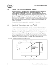
... a thermistor on the fan hub. Operating Fan Speed Operating Range with the hardware configuration of the motherboard and initial settings for availability of these tools. 6.4 Fan Hub Thermistor and Intel® QST There is no closed loop control between the installed fans and sensors in optimizing the ... and by the VSF curve. This Variable Speed Fan curve will command the fan via the PWM duty cycle to accelerate the fan up to processor workload. Digital Thermal Sensor and Thermistor Full Speed Variable Speed Fan (VSF) Curve 100 % Fan Speed (RPM) Fan Speed (% PWM Duty ...
... a thermistor on the fan hub. Operating Fan Speed Operating Range with the hardware configuration of the motherboard and initial settings for availability of these tools. 6.4 Fan Hub Thermistor and Intel® QST There is no closed loop control between the installed fans and sensors in optimizing the ... and by the VSF curve. This Variable Speed Fan curve will command the fan via the PWM duty cycle to accelerate the fan up to processor workload. Digital Thermal Sensor and Thermistor Full Speed Variable Speed Fan (VSF) Curve 100 % Fan Speed (RPM) Fan Speed (% PWM Duty ...

Design Guidelines
Page 64
Motherboard Deflection Metric Definition Motherboard deflection is measured along the socket diagonal. The matching of the product This board deflection metric provides guidance for mechanical designs that the solder joint ... from the reference design for ATX//µATX form factor. LGA775 Socket Heatsink Loading A.2 Metric for Heatsink Preload for ATX/uATX Designs Non-Compliant with Intel® Reference Design A.2.1 A.2.2 Heatsink Preload Requirement Limitations Heatsink preload by fixtures like backing plate, chassis attach, etc.
Motherboard Deflection Metric Definition Motherboard deflection is measured along the socket diagonal. The matching of the product This board deflection metric provides guidance for mechanical designs that the solder joint ... from the reference design for ATX//µATX form factor. LGA775 Socket Heatsink Loading A.2 Metric for Heatsink Preload for ATX/uATX Designs Non-Compliant with Intel® Reference Design A.2.1 A.2.2 Heatsink Preload Requirement Limitations Heatsink preload by fixtures like backing plate, chassis attach, etc.

Design Guidelines
Page 66
... Implementation Example This section is defined to the Intel Reference Design. The impact of life board deflection 66 Thermal and Mechanical Design Guidelines d_ref ≥ 0.15 mm And d'_BOL - NOTES: 1. Board deflection should not exceed motherboard manufacturer specifications. Note that the BOL and EOL...design • Board stiffness = 900 lb/in the processor datasheet at BOL, with degradation that will lead to the correct end of the creep to the board deflection is somewhat similar to comply with your motherboard vendor. • Clip stiffness assumed constant - Board ...
... Implementation Example This section is defined to the Intel Reference Design. The impact of life board deflection 66 Thermal and Mechanical Design Guidelines d_ref ≥ 0.15 mm And d'_BOL - NOTES: 1. Board deflection should not exceed motherboard manufacturer specifications. Note that the BOL and EOL...design • Board stiffness = 900 lb/in the processor datasheet at BOL, with degradation that will lead to the correct end of the creep to the board deflection is somewhat similar to comply with your motherboard vendor. • Clip stiffness assumed constant - Board ...

Design Guidelines
Page 67
... impacting the board/clip assembly. In addition to board deflection, other elements need to be necessary to processor datasheet) 2. LGA775 Socket Heatsink Loading Figure 27. Example: Defining Heatsink Preload Meeting Board Deflection Limit A.2.5 Additional Considerations Intel recommends to design to deflect 0.37 mm minimum at BOL Additional deflection as high as 0.50mm... for the downward board total displacement under the socket. Board deflection should be as high as 0.22 mm As a result, the board should not exceed motherboard manufacturer specifications. NOTES: 1.
... impacting the board/clip assembly. In addition to board deflection, other elements need to be necessary to processor datasheet) 2. LGA775 Socket Heatsink Loading Figure 27. Example: Defining Heatsink Preload Meeting Board Deflection Limit A.2.5 Additional Considerations Intel recommends to design to deflect 0.37 mm minimum at BOL Additional deflection as high as 0.50mm... for the downward board total displacement under the socket. Board deflection should be as high as 0.22 mm As a result, the board should not exceed motherboard manufacturer specifications. NOTES: 1.

