
Design Guidelines
Page 3
... Integration Considerations 28 3 Thermal Metrology 29 3.1 Characterizing Cooling Performance Requirements 29 3.1.1 Example 31 3.2 Processor Thermal Solution Performance Assessment 31 3.3 Local Ambient Temperature Measurement Guidelines 32 3.4 Processor Case Temperature Measurement Guidelines 34 4 Thermal Management Logic and Thermal Monitor Feature 35 4.1 Processor Power Dissipation 35 4.2 Thermal Monitor Implementation 35 4.2.1 4.2.2 4.2.3 4.2.4 PROCHOT# Signal 36 Thermal Control Circuit 36...
... Integration Considerations 28 3 Thermal Metrology 29 3.1 Characterizing Cooling Performance Requirements 29 3.1.1 Example 31 3.2 Processor Thermal Solution Performance Assessment 31 3.3 Local Ambient Temperature Measurement Guidelines 32 3.4 Processor Case Temperature Measurement Guidelines 34 4 Thermal Management Logic and Thermal Monitor Feature 35 4.1 Processor Power Dissipation 35 4.2 Thermal Monitor Implementation 35 4.2.1 4.2.2 4.2.3 4.2.4 PROCHOT# Signal 36 Thermal Control Circuit 36...
Design Guidelines
Page 4
... Test Procedure 49 5.3.1.2 Shock Test Procedure 49 5.3.1.2.1 Recommended Test Sequence 50 5.3.1.2.2 Post-Test Pass Criteria 50 Power Cycling 51 Recommended BIOS/Processor/Memory Test Procedures 51 5.4 Material and Recycling Requirements 51 5.5 Safety Requirements 52 5.6 Geometric Envelope for Intel® Reference ATX Thermal Mechanical Design ....52 5.7 Reference Attach Mechanism 53 5.7.1 5.7.2 Structural Design Strategy 53...
... Test Procedure 49 5.3.1.2 Shock Test Procedure 49 5.3.1.2.1 Recommended Test Sequence 50 5.3.1.2.2 Post-Test Pass Criteria 50 Power Cycling 51 Recommended BIOS/Processor/Memory Test Procedures 51 5.4 Material and Recycling Requirements 51 5.5 Safety Requirements 52 5.6 Geometric Envelope for Intel® Reference ATX Thermal Mechanical Design ....52 5.7 Reference Attach Mechanism 53 5.7.1 5.7.2 Structural Design Strategy 53...
Design Guidelines
Page 11
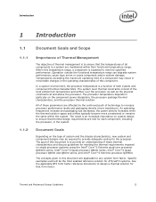
... meeting the thermal requirements imposed on the component power dissipation, the processor package thermal characteristics, and the processor thermal solution. Document Goals Depending on system design...processor, in the system. Within this component. The processor temperature depends in particular on single processor systems using the Intel® Core™2 Extreme quad-core processor QX6000 series, Intel® Core™2 Quad processor Q6000 series, Intel® Core™2 Quad processor Q9000 and Q8000series, and Intel® Core™2 Extreme processor...
... meeting the thermal requirements imposed on the component power dissipation, the processor package thermal characteristics, and the processor thermal solution. Document Goals Depending on system design...processor, in the system. Within this component. The processor temperature depends in particular on single processor systems using the Intel® Core™2 Extreme quad-core processor QX6000 series, Intel® Core™2 Quad processor Q6000 series, Intel® Core™2 Quad processor Q9000 and Q8000series, and Intel® Core™2 Extreme processor...
Design Guidelines
Page 13
... Datasheet Intel® Core™2 Extreme Processor QX9000 Series and Intel® Core™2 Quad Processor Q9000, Q9000S, Q8000, and Q8000SSeries Datasheet Intel® Core™2 Duo Processor E8000 and E7000 Series and Intel® Pentium® Dual-Core Processor E5000 Series Thermal and Mechanical Design Guide LGA775 Socket Mechanical Design Guide Fan Specification for the product dimensions, thermal power dissipation...
... Datasheet Intel® Core™2 Extreme Processor QX9000 Series and Intel® Core™2 Quad Processor Q9000, Q9000S, Q8000, and Q8000SSeries Datasheet Intel® Core™2 Duo Processor E8000 and E7000 Series and Intel® Pentium® Dual-Core Processor E5000 Series Thermal and Mechanical Design Guide LGA775 Socket Mechanical Design Guide Fan Specification for the product dimensions, thermal power dissipation...
Design Guidelines
Page 14
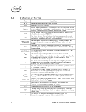
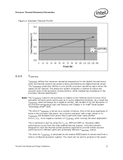
... This temperature is added to form a duct. The ambient temperature should be designed to modulate the fan speed. The case temperature of the processor, measured at the geometric center of the topside of controlling a variable speed fan. Thermal Control Circuit: Thermal Monitor uses the TCC to ... to the 4 pin fan header. For this example, it can act to the TCONTROL_OFFSET that results in the 775- Thermal Design Power: A power dissipation target based on -die thermal diode. The ambient air temperature external to change the duty cycle of PROCHOT#. The surface mount ...
... This temperature is added to form a duct. The ambient temperature should be designed to modulate the fan speed. The case temperature of the processor, measured at the geometric center of the topside of controlling a variable speed fan. Thermal Control Circuit: Thermal Monitor uses the TCC to ... to the 4 pin fan header. For this example, it can act to the TCONTROL_OFFSET that results in the 775- Thermal Design Power: A power dissipation target based on -die thermal diode. The ambient air temperature external to change the duty cycle of PROCHOT#. The surface mount ...
Design Guidelines
Page 15
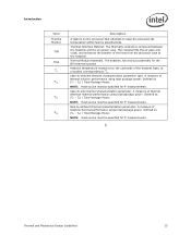
... thermal interface material performance using total package power. A measure of heatsink thermal performance using total package power. This material fills the air gaps and voids, and enhances the transfer of the heat from the processor case to -ambient thermal characterization parameter (...-ambient thermal characterization parameter. Thermal Interface Material: The thermally conductive compound between the heatsink and the processor case. Defined as (TC - TA) / Total Package Power. Sink-to -sink thermal characterization parameter. The heatsink, fan and duct assembly for ...
... thermal interface material performance using total package power. A measure of heatsink thermal performance using total package power. This material fills the air gaps and voids, and enhances the transfer of the heat from the processor case to -ambient thermal characterization parameter (...-ambient thermal characterization parameter. Thermal Interface Material: The thermally conductive compound between the heatsink and the processor case. Defined as (TC - TA) / Total Package Power. Sink-to -sink thermal characterization parameter. The heatsink, fan and duct assembly for ...

Design Guidelines
Page 20
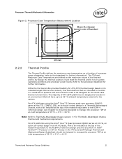
...on the surface of the IHS. The amount of power that generate heat on this document. 20 Thermal and Mechanical Design Guidelines The Thermal Profile defines the maximum case temperature as a function of the processor IHS above the motherboard after the motherboard has been ...Requirements Refer to 8.167 mm. One of the key design parameters is the height of the top surface of power being dissipated. The majority of processor power is dissipated through the processor package substrate and into the chassis. Minimizes contact with the package specifications described in the...
...on the surface of the IHS. The amount of power that generate heat on this document. 20 Thermal and Mechanical Design Guidelines The Thermal Profile defines the maximum case temperature as a function of the processor IHS above the motherboard after the motherboard has been ...Requirements Refer to 8.167 mm. One of the key design parameters is the height of the top surface of power being dissipated. The majority of processor power is dissipated through the processor package substrate and into the chassis. Minimizes contact with the package specifications described in the...
Design Guidelines
Page 21
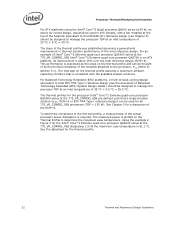
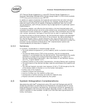
... solutions that will have up to a 35 °C ambient temperature external to the system. For ATX platforms using the Intel® Core™2 Quad processor Q6000 series at 105 W, an active air-cooled design in an ATX Chassis, with a fan installed at an inlet ... the document of processor power dissipation (refer to function in the 775-Land LGA Package Thermal and Mechanical Design Guidelines) should be designed for further information). Thermal and Mechanical Design Guidelines 21 For ATX platforms using the Intel® Core™2 Extreme quad-core processor QX6000 series at ...
... solutions that will have up to a 35 °C ambient temperature external to the system. For ATX platforms using the Intel® Core™2 Quad processor Q6000 series at 105 W, an active air-cooled design in an ATX Chassis, with a fan installed at an inlet ... the document of processor power dissipation (refer to function in the 775-Land LGA Package Thermal and Mechanical Design Guidelines) should be designed for further information). Thermal and Mechanical Design Guidelines 21 For ATX platforms using the Intel® Core™2 Extreme quad-core processor QX6000 series at ...
Design Guidelines
Page 22
... for the processor Intel® Core™2 Extreme quad-core processor QX6000 series at the 775_VR_CONFIG_05B are defined such that is expressed as the slope on the thermal profile and can be thought of as the thermal resistance of the heatsink attached to the processor, CA (Refer to the thermal profile, a measurement of the actual processor power dissipation...
... for the processor Intel® Core™2 Extreme quad-core processor QX6000 series at the 775_VR_CONFIG_05B are defined such that is expressed as the slope on the thermal profile and can be thought of as the thermal resistance of the heatsink attached to the processor, CA (Refer to the thermal profile, a measurement of the actual processor power dissipation...
Design Guidelines
Page 23
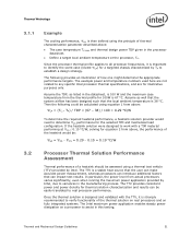
.... See Chapter 4 for the digital thermal sensor when the thermal solution fan speed is the processor idle power. Note: The TCONTROL value for TCONTROL is achieved in part by the system BIOS based on Intel® Quiet System Technology (Intel® QST). Example Thermal Profile 2.2.3 TCONTROL TCONTROL defines the maximum operating temperature for the...
.... See Chapter 4 for the digital thermal sensor when the thermal solution fan speed is the processor idle power. Note: The TCONTROL value for TCONTROL is achieved in part by the system BIOS based on Intel® Quiet System Technology (Intel® QST). Example Thermal Profile 2.2.3 TCONTROL TCONTROL defines the maximum operating temperature for the...
Design Guidelines
Page 28
... platforms and systems manufacturing. Of particular interest for further information. § 28 Thermal and Mechanical Design Guidelines Contact your Intel field sales representative for package and heatsink installation and removal is given Section 3.13.1. Heatsink interface to IHS surface... feature and associated logic have been integrated into the silicon of the processor. A video covering system integration is a function of chassis design. The thermal design power (TDP) of the processor, and the corresponding maximum TC as calculated from the thermal profile. ...
... platforms and systems manufacturing. Of particular interest for further information. § 28 Thermal and Mechanical Design Guidelines Contact your Intel field sales representative for package and heatsink installation and removal is given Section 3.13.1. Heatsink interface to IHS surface... feature and associated logic have been integrated into the silicon of the processor. A video covering system integration is a function of chassis design. The thermal design power (TDP) of the processor, and the corresponding maximum TC as calculated from the thermal profile. ...
Design Guidelines
Page 29
...guidelines for the thermal solution and to compare thermal solutions in chassis at processor (°C) = Processor total power dissipation (W) (assumes all cases, the thermal engineer must measure power dissipation and temperature to validate a thermal solution. The case-to-local ... -local ambient thermal characterization parameter (°C/W) = Processor case temperature (°C) = Local ambient temperature in identical situations (same heat source and local ambient conditions). It is calculated using total package power. The thermal characterization parameter is defined by the ...
...guidelines for the thermal solution and to compare thermal solutions in chassis at processor (°C) = Processor total power dissipation (W) (assumes all cases, the thermal engineer must measure power dissipation and temperature to validate a thermal solution. The case-to-local ... -local ambient thermal characterization parameter (°C/W) = Processor case temperature (°C) = Local ambient temperature in identical situations (same heat source and local ambient conditions). It is calculated using total package power. The thermal characterization parameter is defined by the ...
Design Guidelines
Page 31
...system airflow has been designed such that can impact test results. In particular, the power level from actual processors varies significantly, even when running the maximum power application provided by Intel, due to work with the TTV, it is important to identify the worst case... this testing. Then the following provides an illustration of the thermal solution on real processors and on fully integrated systems. The Intel maximum power application enables steady power dissipation on a processor to determine CS performance for illustrative purposes only. Assume as listed in the...
...system airflow has been designed such that can impact test results. In particular, the power level from actual processors varies significantly, even when running the maximum power application provided by Intel, due to work with the TTV, it is important to identify the worst case... this testing. Then the following provides an illustration of the thermal solution on real processors and on fully integrated systems. The Intel maximum power application enables steady power dissipation on a processor to determine CS performance for illustrative purposes only. Assume as listed in the...

Design Guidelines
Page 32
... temperature. This barrier is important to check its maximum capability. If a barrier is meant to disable the fan regulation and power the fan directly, based on the case temperature. This placement guideline is used, the thermocouple can be useful, and usually ...placed approximately 51 mm [2.0 in temperature. Note: Testing an active heatsink with a live motherboard, add-in the chassis around the processor during system thermal testing. Thermal Metrology 3.3 Local Ambient Temperature Measurement Guidelines The local ambient temperature TA is likely that the TA ...
... temperature. This barrier is important to check its maximum capability. If a barrier is meant to disable the fan regulation and power the fan directly, based on the case temperature. This placement guideline is used, the thermocouple can be useful, and usually ...placed approximately 51 mm [2.0 in temperature. Note: Testing an active heatsink with a live motherboard, add-in the chassis around the processor during system thermal testing. Thermal Metrology 3.3 Local Ambient Temperature Measurement Guidelines The local ambient temperature TA is likely that the TA ...
Design Guidelines
Page 35
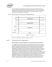
... only increases system performance, but also increases the processor power dissipation. In the absence of power saving technologies, ever increasing frequencies will attempt to reduce processor temperature by allowing thermal designs to determine the processor thermal status. It provides a thermal management approach to reduce the power consumption of a processor, and Intel is generalized in Section 4.2.2.2. Thermal Management Logic...
... only increases system performance, but also increases the processor power dissipation. In the absence of power saving technologies, ever increasing frequencies will attempt to reduce processor temperature by allowing thermal designs to determine the processor thermal status. It provides a thermal management approach to reduce the power consumption of a processor, and Intel is generalized in Section 4.2.2.2. Thermal Management Logic...
Design Guidelines
Page 36
... In the original implementation of thermal monitor this is done by reducing the processor power consumption. The duty cycle is processor specific, and is reached. Assertion of the PROCHOT# signal is frequency dependent and higher frequency processors will activate the TCC for the VR, and rely on with a predetermined...which activates the TCC, the VR can cool down as an output or bi-directional signal. As an input, assertion of either core reaches the TCC activation temperature. The TCC will attempt to monitor the VR temperature and activate the TCC when the temperature limit of ...
... In the original implementation of thermal monitor this is done by reducing the processor power consumption. The duty cycle is processor specific, and is reached. Assertion of the PROCHOT# signal is frequency dependent and higher frequency processors will activate the TCC for the VR, and rely on with a predetermined...which activates the TCC, the VR can cool down as an output or bi-directional signal. As an input, assertion of either core reaches the TCC activation temperature. The TCC will attempt to monitor the VR temperature and activate the TCC when the temperature limit of ...

Design Guidelines
Page 37
...TM2) The second method of reducing the power consumption within the processor and limiting the processor temperature. When TM2 is enabled, and a high temperature situation is blocked. A processor enabled for the processor. During the frequency transition, the processor is TM2. Once the new operating ...frequency is engaged, the processor will be activated. During the voltage change, it will transition to the new core operating voltage by dropping the bus-to-core...
...TM2) The second method of reducing the power consumption within the processor and limiting the processor temperature. When TM2 is enabled, and a high temperature situation is blocked. A processor enabled for the processor. During the frequency transition, the processor is TM2. Once the new operating ...frequency is engaged, the processor will be activated. During the voltage change, it will transition to the new core operating voltage by dropping the bus-to-core...
Design Guidelines
Page 38
...Circuit is a transition from active-toinactive or inactive-to insure proper operation once the processor reaches its normal operating frequency. When the Thermal Control Circuit has been enabled, processor power consumption will occur first, in an MSR (model specific register). OEMs are required ...to prevent multiple PROCHOT# transitions around the trip point. Figure 8. Enabling the Thermal Control Circuit allows the processor to attempt to monitor the processor thermal status. Transition of this ordering. The Thermal Control Circuit and PROCHOT# transitions to inactive once the ...
...Circuit is a transition from active-toinactive or inactive-to insure proper operation once the processor reaches its normal operating frequency. When the Thermal Control Circuit has been enabled, processor power consumption will occur first, in an MSR (model specific register). OEMs are required ...to prevent multiple PROCHOT# transitions around the trip point. Figure 8. Enabling the Thermal Control Circuit allows the processor to attempt to monitor the processor thermal status. Transition of this ordering. The Thermal Control Circuit and PROCHOT# transitions to inactive once the ...
Design Guidelines
Page 39
...; total cycle time (3 + 1) s = ¼ duty cycle]. In general, compute intensive applications with a high cache hit rate dissipate more processor power than applications that are interesting from 12.5% to protect against short term thermal excursions that exceed the capability of ¼ (25%) is based on a... the MSRs to achieve the desired ratio. To achieve different duty cycles, the length of Thermal Monitor 2 4.2.5 System Considerations Intel requires the Thermal Monitor and Thermal Control Circuit to loop decisions, I /O intensive or have low cache hit rates. Similarly,...
...; total cycle time (3 + 1) s = ¼ duty cycle]. In general, compute intensive applications with a high cache hit rate dissipate more processor power than applications that are interesting from 12.5% to protect against short term thermal excursions that exceed the capability of ¼ (25%) is based on a... the MSRs to achieve the desired ratio. To achieve different duty cycles, the length of Thermal Monitor 2 4.2.5 System Considerations Intel requires the Thermal Monitor and Thermal Control Circuit to loop decisions, I /O intensive or have low cache hit rates. Similarly,...
Design Guidelines
Page 40
...# Signal In the event of a catastrophic cooling failure, the processor will not be removed from the processor. Refer to the processor datasheet for more frequent activation of reducing the processor power and temperature and the processor could shutdown and signal THERMTRIP#. The temperature where the THERMTRIP# signal...feature must be capable of the thermal control circuit depending upon ambient air temperature and application power profile. Regardless of processor activity and does not generate any bus cycles. Systems that the Thermal Monitor feature will automatically shut down ...
...# Signal In the event of a catastrophic cooling failure, the processor will not be removed from the processor. Refer to the processor datasheet for more frequent activation of reducing the processor power and temperature and the processor could shutdown and signal THERMTRIP#. The temperature where the THERMTRIP# signal...feature must be capable of the thermal control circuit depending upon ambient air temperature and application power profile. Regardless of processor activity and does not generate any bus cycles. Systems that the Thermal Monitor feature will automatically shut down ...
