
Data Sheet
Page 3
Contents 1 Introduction ...11 1.1 Terminology ...12 1.1.1 Processor Terminology Definitions 12 1.2 References ...14 2 Electrical Specifications 15 2.1 Power and Ground Lands 15 2.2 Decoupling Guidelines 15 2.2.1 VCC Decoupling 15 2.2.2 Vtt Decoupling 15 2.2.3 FSB Decoupling 16 2.3 Voltage Identification 16 2.4 Reserved, Unused, and TESTHI Signals 18 2.5 Power Segment Identifier (PSID 18 2.6 Voltage and Current Specification 19 2.6.1 Absolute Maximum and Minimum...
Contents 1 Introduction ...11 1.1 Terminology ...12 1.1.1 Processor Terminology Definitions 12 1.2 References ...14 2 Electrical Specifications 15 2.1 Power and Ground Lands 15 2.2 Decoupling Guidelines 15 2.2.1 VCC Decoupling 15 2.2.2 Vtt Decoupling 15 2.2.3 FSB Decoupling 16 2.3 Voltage Identification 16 2.4 Reserved, Unused, and TESTHI Signals 18 2.5 Power Segment Identifier (PSID 18 2.6 Voltage and Current Specification 19 2.6.1 Absolute Maximum and Minimum...

Data Sheet
Page 4
...PECI Fault Handling Requirements 87 5.3.2.4 PECI GetTemp0() Error Code Support 87 6 Features ...89 6.1 Power-On Configuration Options 89 6.2 Clock Control and Low Power States 89 6.2.1 Normal State 90 6.2.2 HALT and Extended HALT Powerdown States 90 6.2.2.1 HALT ...Requirements 97 7.3.1 Fan Heatsink Power Supply 97 7.4 Thermal Specifications 99 7.4.1 Boxed Processor Cooling Requirements 99 7.4.2 Variable Speed Fan 100 7.5 Boxed Intel® Core™2 Extreme Processor QX9650 Specifications 101 7.5.1 Boxed Intel® Core™2 Extreme Processor QX9650 Fan Heatsink Weight........ ...
...PECI Fault Handling Requirements 87 5.3.2.4 PECI GetTemp0() Error Code Support 87 6 Features ...89 6.1 Power-On Configuration Options 89 6.2 Clock Control and Low Power States 89 6.2.1 Normal State 90 6.2.2 HALT and Extended HALT Powerdown States 90 6.2.2.1 HALT ...Requirements 97 7.3.1 Fan Heatsink Power Supply 97 7.4 Thermal Specifications 99 7.4.1 Boxed Processor Cooling Requirements 99 7.4.2 Variable Speed Fan 100 7.5 Boxed Intel® Core™2 Extreme Processor QX9650 Specifications 101 7.5.1 Boxed Intel® Core™2 Extreme Processor QX9650 Fan Heatsink Weight........ ...

Data Sheet
Page 5
... 78 5-2 Intel® Core™2 Extreme Processor QX9650 Thermal Profile 79 5-3 Intel® Core™2 Quad Processor Q9000 and Q8000 Series Thermal Profile 80 5-4 Intel® Core™2 Quad Processor Q9000S and Q8000S Series Thermal Profile 81 5-5 Case Temperature (TC) Measurement Location 82 5-6 Thermal Monitor 2 Frequency and Voltage Ordering 84 5-7 Conceptual Fan Control Diagram on PECI-Based Platforms 86 6-1 Processor Low Power State Machine...
... 78 5-2 Intel® Core™2 Extreme Processor QX9650 Thermal Profile 79 5-3 Intel® Core™2 Quad Processor Q9000 and Q8000 Series Thermal Profile 80 5-4 Intel® Core™2 Quad Processor Q9000S and Q8000S Series Thermal Profile 81 5-5 Case Temperature (TC) Measurement Location 82 5-6 Thermal Monitor 2 Frequency and Voltage Ordering 84 5-7 Conceptual Fan Control Diagram on PECI-Based Platforms 86 6-1 Processor Low Power State Machine...

Data Sheet
Page 6
... Assignment 55 4-3 Signal Description 64 5-1 Processor Thermal Specifications 76 5-2 Intel® Core™2 Extreme Processor QX9770 Thermal Profile 78 5-3 Intel® Core™2 Extreme Processor QX9650 Thermal Profile 79 5-4 Intel® Core™2 Quad Processor Q9000 and Q8000 Series Thermal Profile 80 5-5 Intel® Core™2 Quad Processor Q9000S and Q8000S Series Thermal Profile 81 5-6 GetTemp0() Error Codes 87 6-1 Power-On Configuration Option Signals 89 7-1 Fan...
... Assignment 55 4-3 Signal Description 64 5-1 Processor Thermal Specifications 76 5-2 Intel® Core™2 Extreme Processor QX9770 Thermal Profile 78 5-3 Intel® Core™2 Extreme Processor QX9650 Thermal Profile 79 5-4 Intel® Core™2 Quad Processor Q9000 and Q8000 Series Thermal Profile 80 5-5 Intel® Core™2 Quad Processor Q9000S and Q8000S Series Thermal Profile 81 5-6 GetTemp0() Error Codes 87 6-1 Power-On Configuration Option Signals 89 7-1 Fan...

Data Sheet
Page 9
... • Two 6 MB Level 2 caches (Intel® Core™2 Extreme processor QX9000 series, Intel® Core™2 Quad processor Q9650, Q9550, Q9550S, and Q9450) • Two 4 MB Level 2 caches (Intel® Core™2 Quad processor Q9505, Q9505S, Q8400, and Q8400S) • Two 3 MB Level 2 caches (Intel® Core™2 Quad processor Q9400, Q9400S, and Q9300) • Two 2 MB Level 2 caches (Intel® Core™2 Quad processor Q8200, Q8200S, and Q8300) • Intel® HD Boost utilizing...
... • Two 6 MB Level 2 caches (Intel® Core™2 Extreme processor QX9000 series, Intel® Core™2 Quad processor Q9650, Q9550, Q9550S, and Q9450) • Two 4 MB Level 2 caches (Intel® Core™2 Quad processor Q9505, Q9505S, Q8400, and Q8400S) • Two 3 MB Level 2 caches (Intel® Core™2 Quad processor Q9400, Q9400S, and Q9300) • Two 2 MB Level 2 caches (Intel® Core™2 Quad processor Q8200, Q8200S, and Q8300) • Intel® HD Boost utilizing...

Data Sheet
Page 11
... Q9550S, Q9505S, and Q9400S. • The Intel® Core™2 Quad processor Q8000 series refers to the Q8200, Q8300, Q8400. • The Intel® Core™2 Quad processor Q8000S series refers to 12.4 GB/s. The processors feature 1600 MHz and 1333 MHz front side bus (FSB) frequencies.The processors also feature two independent but shared 12 MB of L2 cache (2x6M), two independent...
... Q9550S, Q9505S, and Q9400S. • The Intel® Core™2 Quad processor Q8000 series refers to the Q8200, Q8300, Q8400. • The Intel® Core™2 Quad processor Q8000S series refers to 12.4 GB/s. The processors feature 1600 MHz and 1333 MHz front side bus (FSB) frequencies.The processors also feature two independent but shared 12 MB of L2 cache (2x6M), two independent...

Data Sheet
Page 12
... L2 caches. • Intel® Core™2 Quad processor Q8000 Series - Low power Quad core processor in the FCLGA8 package with two 6 MB L2 caches or two 3 MB L2 caches. • Intel® Core™2 Quad Processor Q8000S Series - For additional information refer to a hex 'A' (H= High logic level, L= Low logic level). Processor die with the processor at the IHS surface. • Retention mechanism (RM) - Component thermal solutions interface with integrated L2 cache. • LGA775 socket...
... L2 caches. • Intel® Core™2 Quad processor Q8000 Series - Low power Quad core processor in the FCLGA8 package with two 6 MB L2 caches or two 3 MB L2 caches. • Intel® Core™2 Quad Processor Q8000S Series - For additional information refer to a hex 'A' (H= High logic level, L= Low logic level). Processor die with the processor at the IHS surface. • Retention mechanism (RM) - Component thermal solutions interface with integrated L2 cache. • LGA775 socket...

Data Sheet
Page 13
... for some classes of viruses or worms that can thus help improve the overall security of Intel 64 architecture. Introduction memory and I /Os biased, or receive any I /O transactions as well as indicated on processor utilization. Processors may lower average power consumption (in conjunction with moisture sensitivity labeling (MSL) as interrupt messages pass between the...
... for some classes of viruses or worms that can thus help improve the overall security of Intel 64 architecture. Introduction memory and I /Os biased, or receive any I /O transactions as well as indicated on processor utilization. Processors may lower average power consumption (in conjunction with moisture sensitivity labeling (MSL) as interrupt messages pass between the...
Data Sheet
Page 14
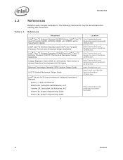
... Intel® Core™2 Extreme Processor QX9000 Series, Intel® Core™2 Quad Processor Q9000, Q9000S, Q8000, and Q8000S Series Specification Update Intel® Core™2 Extreme Processor and Intel® Core™2 Quad Processor Thermal and Mechanical Design Guidelines Intel® Core™2 Extreme Processor QX6800 and Intel® Core™2 Extreme Processor QX9770 Thermal and Mechanical Design Guidelines Voltage Regulator-Down (VRD) 11.0 Processor Power Delivery Design Guidelines For Desktop LGA775...
... Intel® Core™2 Extreme Processor QX9000 Series, Intel® Core™2 Quad Processor Q9000, Q9000S, Q8000, and Q8000S Series Specification Update Intel® Core™2 Extreme Processor and Intel® Core™2 Quad Processor Thermal and Mechanical Design Guidelines Intel® Core™2 Extreme Processor QX6800 and Intel® Core™2 Extreme Processor QX9770 Thermal and Mechanical Design Guidelines Voltage Regulator-Down (VRD) 11.0 Processor Power Delivery Design Guidelines For Desktop LGA775...

Data Sheet
Page 15
... signals. Failure to sag below their minimum specified values if bulk decoupling is capable of low ESR bulk capacitors and high frequency ceramic capacitors. Consult the Voltage Regulator-Down (VRD) 11.0 Processor Power Delivery Design Guidelines For Desktop LGA775 Socket. A conservative decoupling solution would consist of a combination of generating large current swings. Datasheet 15...
... signals. Failure to sag below their minimum specified values if bulk decoupling is capable of low ESR bulk capacitors and high frequency ceramic capacitors. Consult the Voltage Regulator-Down (VRD) 11.0 Processor Power Delivery Design Guidelines For Desktop LGA775 Socket. A conservative decoupling solution would consist of a combination of generating large current swings. Datasheet 15...
Data Sheet
Page 16
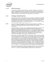
...Note that a low-to-high or high-to the value defined by the processor during manufacturing such that is reflected by the Voltage Regulator-Down (VRD) 11.0 Processor Power Delivery Design Guidelines For Desktop LGA775 Socket. The processor provides the ability...be calibrated during a power management event (Thermal Monitor 2, Enhanced Intel SpeedStep® technology, or Extended HALT State). The processor uses eight voltage identification signals, VID[7:0], to the Intel® Core™2 Extreme Processor QX9000 Series and Intel® Core™2 Quad Processor Q9000, Q9000S, Q8000,...
...Note that a low-to-high or high-to the value defined by the processor during manufacturing such that is reflected by the Voltage Regulator-Down (VRD) 11.0 Processor Power Delivery Design Guidelines For Desktop LGA775 Socket. The processor provides the ability...be calibrated during a power management event (Thermal Monitor 2, Enhanced Intel SpeedStep® technology, or Extended HALT State). The processor uses eight voltage identification signals, VID[7:0], to the Intel® Core™2 Extreme Processor QX9000 Series and Intel® Core™2 Quad Processor Q9000, Q9000S, Q8000,...

Data Sheet
Page 18
... unconnected, however this may interfere with a 65 W or 95 W TDP capable VR may draw too much power and cause a potential VR issue. 18 Datasheet The TESTHI signals may interfere with future processors. A matched resistor must be used outputs must be left as no connects as GTL+ termination is capable of... All RESERVED lands must be individually connected to VTT via a pull-up resistor values used when tying bidirectional signals to detect if the processor in use requires more power than the platform voltage regulator (VR) is provided on -die termination has been included by the...
... unconnected, however this may interfere with a 65 W or 95 W TDP capable VR may draw too much power and cause a potential VR issue. 18 Datasheet The TESTHI signals may interfere with future processors. A matched resistor must be used outputs must be left as no connects as GTL+ termination is capable of... All RESERVED lands must be individually connected to VTT via a pull-up resistor values used when tying bidirectional signals to detect if the processor in use requires more power than the platform voltage regulator (VR) is provided on -die termination has been included by the...

Data Sheet
Page 20
... Cache) Processor Number VCC for 775_VR_CONFIG_05A: Q9650 3.0 GHz (12 MB Cache) Q9550 2.83 GHz (12 MB Cache) Q9550S Q9505 2.83 GHz (12 MB Cache) Refer to Table 2-4 and 2.83 GHz (8 MB Cache) Figure 2-1 Q9505S 2.83 GHz (8 MB Cache) Q9450 2.66 GHz (12 MB Cache) Q9400 2.66 GHz (6 MB Cache) V Q9400S 2.66 GHz (6 MB Cache) Q9300 2.50 GHz (6 MB Cache) Q8400 2.66 GHz (8 MB Cache...
... Cache) Processor Number VCC for 775_VR_CONFIG_05A: Q9650 3.0 GHz (12 MB Cache) Q9550 2.83 GHz (12 MB Cache) Q9550S Q9505 2.83 GHz (12 MB Cache) Refer to Table 2-4 and 2.83 GHz (8 MB Cache) Figure 2-1 Q9505S 2.83 GHz (8 MB Cache) Q9450 2.66 GHz (12 MB Cache) Q9400 2.66 GHz (6 MB Cache) V Q9400S 2.66 GHz (6 MB Cache) Q9300 2.50 GHz (6 MB Cache) Q8400 2.66 GHz (8 MB Cache...
Data Sheet
Page 21
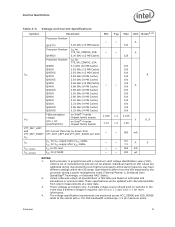
... only. These voltages are calibrated during a power management event (Thermal Monitor 2, Enhanced Intel SpeedStep® Technology, or Extended HALT State). 2. Voltage and Current Specifications Symbol Parameter Processor Number ICC VTT VTT_OUT_LEFT and VTT_OUT_RIGHT ICC ITT ICC_VCCPLL ICC_GTLREF QX9770 Processor Number QX9650 Processor Number Q9650 Q9550 Q9550S Q9505 Q9505S Q9450 Q9400 Q9400S Q9300 Q8400 Q8300 Q8200 Q8400S Q8200S...
... only. These voltages are calibrated during a power management event (Thermal Monitor 2, Enhanced Intel SpeedStep® Technology, or Extended HALT State). 2. Voltage and Current Specifications Symbol Parameter Processor Number ICC VTT VTT_OUT_LEFT and VTT_OUT_RIGHT ICC ITT ICC_VCCPLL ICC_GTLREF QX9770 Processor Number QX9650 Processor Number Q9650 Q9550 Q9550S Q9505 Q9505S Q9450 Q9400 Q9400S Q9300 Q8400 Q8300 Q8200 Q8400S Q8200S...

Data Sheet
Page 26
...power planes for improved noise tolerance as VTT. This configuration allows for each processor (and chipset), separate VCC and VTT supplies are necessary. Termination resistors (RTT) for GTL+ signals defined as processor...ADSTB1# DSTBP0#, DSTBN0# DSTBP1#, DSTBN1# DSTBP2#, DSTBN2# DSTBP3#, DSTBN3# 26 Datasheet Intel chipsets will also provide on the motherboard (see Table 2-13 for the source synchronous ... Table 2-6. This technology provides improved noise margins and reduced ringing through low voltage swings and controlled edge rates. The GTL+ inputs require a reference...
...power planes for improved noise tolerance as VTT. This configuration allows for each processor (and chipset), separate VCC and VTT supplies are necessary. Termination resistors (RTT) for GTL+ signals defined as processor...ADSTB1# DSTBP0#, DSTBN0# DSTBP1#, DSTBN1# DSTBP2#, DSTBN2# DSTBP3#, DSTBN3# 26 Datasheet Intel chipsets will also provide on the motherboard (see Table 2-13 for the source synchronous ... Table 2-6. This technology provides improved noise margins and reduced ringing through low voltage swings and controlled edge rates. The GTL+ inputs require a reference...

Data Sheet
Page 27
... BR0#, TDO, TDO_M, FCx NOTES: 1. The value of 2) Signal Group Type Signals1 GTL+ Strobes CMOS Open Drain Output Open Drain Input/Output FSB Clock Power/Other Synchronous to BCLK[1:0] ADSTB[1:0]#, DSTBP[3:0]#, DSTBN[3:0]# A20M#, DPSLP#, DPRSTP#, IGNNE#, INIT#, LINT0/ INTR, LINT1/NMI, SMI#3, STPCLK#, PWRGOOD, SLP#, TCK,... during the active-to support a debug port interposer. Datasheet 27 NOTES: 1. See Section 6.1 for more information. Table 2-8. In processor systems where no connects. 3. Signals that do not have RTT, nor are used to -inactive edge of RESET# defines the...
... BR0#, TDO, TDO_M, FCx NOTES: 1. The value of 2) Signal Group Type Signals1 GTL+ Strobes CMOS Open Drain Output Open Drain Input/Output FSB Clock Power/Other Synchronous to BCLK[1:0] ADSTB[1:0]#, DSTBP[3:0]#, DSTBN[3:0]# A20M#, DPSLP#, DPRSTP#, IGNNE#, INIT#, LINT0/ INTR, LINT1/NMI, SMI#3, STPCLK#, PWRGOOD, SLP#, TCK,... during the active-to support a debug port interposer. Datasheet 27 NOTES: 1. See Section 6.1 for more information. Table 2-8. In processor systems where no connects. 3. Signals that do not have RTT, nor are used to -inactive edge of RESET# defines the...

Data Sheet
Page 28
... at a receiving agent that will be interpreted as a logical low value. 3. Measured at the processor core (pads) unless otherwise stated. Electrical Specifications 2.7.2 CMOS and Open... See Section 6.2 for additional timing requirements for entering and leaving the low power states. 2.7.3 Processor DC Specifications The processor DC specifications in this table apply to all specifications in order for the...defined at VTT * 0.2V. 3. See Section 2.7.3 for the processor to all frequencies and cache sizes unless otherwise stated. All specifications apply to in this table ...
... at a receiving agent that will be interpreted as a logical low value. 3. Measured at the processor core (pads) unless otherwise stated. Electrical Specifications 2.7.2 CMOS and Open... See Section 6.2 for additional timing requirements for entering and leaving the low power states. 2.7.3 Processor DC Specifications The processor DC specifications in this table apply to all specifications in order for the...defined at VTT * 0.2V. 3. See Section 2.7.3 for the processor to all frequencies and cache sizes unless otherwise stated. All specifications apply to in this table ...

Data Sheet
Page 30
... voltage called GTLREF. Each GTLREF land must be generated on the PECI bus. 3. COMP[3:0] and COMP8 resistors are to powered devices on the system board using high precision voltage divider circuits. PECI DC Electrical Limits Symbol Definition and Conditions Min Max ... Vp-p NOTES: 1. One node is used on -die termination. See Table 2-7 for the system host. Valid high and low levels are integrated into the processor silicon. GTL+ Bus Resistance Definitions Symbol Parameter Min GTLREF_PU GTLREF_PD RTT COMP[3:0] COMP8 GTLREF pull up resistor GTLREF pull down resistor ...
... voltage called GTLREF. Each GTLREF land must be generated on the PECI bus. 3. COMP[3:0] and COMP8 resistors are to powered devices on the system board using high precision voltage divider circuits. PECI DC Electrical Limits Symbol Definition and Conditions Min Max ... Vp-p NOTES: 1. One node is used on -die termination. See Table 2-7 for the system host. Valid high and low levels are integrated into the processor silicon. GTL+ Bus Resistance Definitions Symbol Parameter Min GTLREF_PU GTLREF_PD RTT COMP[3:0] COMP8 GTLREF pull up resistor GTLREF pull down resistor ...

Data Sheet
Page 46
.../Output Common Clock Input/Output Common Clock Input Common Clock Input/Output Asynch CMOS Output Asynch CMOS Output Asynch CMOS Output Power/Other Input Power/Other Input Power/Other Input Power/Other Input Power/Other Input Source Synch Input/Output Source Synch Input/Output Source Synch Input/Output Source Synch Input/Output Source Synch Input...
.../Output Common Clock Input/Output Common Clock Input Common Clock Input/Output Asynch CMOS Output Asynch CMOS Output Asynch CMOS Output Power/Other Input Power/Other Input Power/Other Input Power/Other Input Power/Other Input Source Synch Input/Output Source Synch Input/Output Source Synch Input/Output Source Synch Input/Output Source Synch Input...

Data Sheet
Page 47
... Input/Output Source Synch Input/Output Power/Other Power/Other Power/Other Power/Other Power/Other Power/Other Power/Other Power/Other Power/Other Power/Other Power/Other Power/Other Power/Other Power/Other Power/Other FC31 FC32 J16 H15 Power/Other Power/Other FC33 FC34 H16 J17 Power/Other Power/Other FC35 FC36 H4 AD3 Power/Other Power/Other FC37 FC39 AB3 AA2 Power/Other Power/Other FC40 AM6 FERR#/PBE# R3...
... Input/Output Source Synch Input/Output Power/Other Power/Other Power/Other Power/Other Power/Other Power/Other Power/Other Power/Other Power/Other Power/Other Power/Other Power/Other Power/Other Power/Other Power/Other FC31 FC32 J16 H15 Power/Other Power/Other FC33 FC34 H16 J17 Power/Other Power/Other FC35 FC36 H4 AD3 Power/Other Power/Other FC37 FC39 AB3 AA2 Power/Other Power/Other FC40 AM6 FERR#/PBE# R3...