
Product Specification
Page 5
...Diagram 15 1.2 Online Support ...16 1.3 Operating System Support 16 1.4 Design Specifications 17 1.5 Processor ...20 1.6 System Memory ...21 1.6.1 Memory Features 21 1.6.2 Memory Configurations 23 1.7 Intel® 875P Chipset ...28 1.7.1 AGP ...29 1.7.2 USB...29 1.7.3 IDE Support 30 1.7.4 Real-Time Clock..., CMOS SRAM, and Battery 32 1.7.5 Intel® 82802AC Firmware Hub (FWH 32 1.8 I/O Controller ...32 ...
...Diagram 15 1.2 Online Support ...16 1.3 Operating System Support 16 1.4 Design Specifications 17 1.5 Processor ...20 1.6 System Memory ...21 1.6.1 Memory Features 21 1.6.2 Memory Configurations 23 1.7 Intel® 875P Chipset ...28 1.7.1 AGP ...29 1.7.2 USB...29 1.7.3 IDE Support 30 1.7.4 Real-Time Clock..., CMOS SRAM, and Battery 32 1.7.5 Intel® 82802AC Firmware Hub (FWH 32 1.8 I/O Controller ...32 ...

Product Specification
Page 9
Mic In Connector ...59 20. Processor Fan Connector 64 28. Main Power Connector 65 29. Chassis Intrusion Connector 65 31. States for Components 80 42. Front Panel Audio Connector or Jumper ...
Mic In Connector ...59 20. Processor Fan Connector 64 28. Main Power Connector 65 29. Chassis Intrusion Connector 65 31. States for Components 80 42. Front Panel Audio Connector or Jumper ...

Product Specification
Page 11
1 Product Description What This Chapter Contains 1.1 Overview ...12 1.2 Online Support ...16 1.3 Operating System Support 16 1.4 Design Specifications 17 1.5 Processor ...20 1.6 System Memory ...21 1.7 Intel® 875P Chipset ...28 1.8 I/O Controller ...32 1.9 Audio Subsystem (Optional 34 1.10 LAN Subsystem...37 1.11 Hardware Management Subsystem 38 1.12 Power Management 40 11
1 Product Description What This Chapter Contains 1.1 Overview ...12 1.2 Online Support ...16 1.3 Operating System Support 16 1.4 Design Specifications 17 1.5 Processor ...20 1.6 System Memory ...21 1.7 Intel® 875P Chipset ...28 1.8 I/O Controller ...32 1.9 Audio Subsystem (Optional 34 1.10 LAN Subsystem...37 1.11 Hardware Management Subsystem 38 1.12 Power Management 40 11

Product Specification
Page 12
... Expansion Capabilities I/O Control LAN Hardware Monitor Subsystem Support for an Intel® Pentium® 4 processor in an mPGA478 socket with a 533/800 MHz system bus • Four 184-pin DDR SDRAM Dual Inline Memory Module (DIMM) sockets • Support ...for DDR400 and DDR333 SDRAM DIMMs • Support for up to 4 GB of system memory Intel® 875P Chipset, consisting of: • Intel® 82875P Memory Controller Hub (MCH) • Intel...
... Expansion Capabilities I/O Control LAN Hardware Monitor Subsystem Support for an Intel® Pentium® 4 processor in an mPGA478 socket with a 533/800 MHz system bus • Four 184-pin DDR SDRAM Dual Inline Memory Module (DIMM) sockets • Support ...for DDR400 and DDR333 SDRAM DIMMs • Support for up to 4 GB of system memory Intel® 875P Chipset, consisting of: • Intel® 82875P Memory Controller Hub (MCH) • Intel...

Product Specification
Page 15
...of the Desktop Board D875PBZ. = connector or socket Parallel ATA IDE Connectors (2) Parallel ATA IDE Interface mPGA478 Processor Socket System Bus (533/800 MHz) LAN Connector Intel 82547EI PLC Device CSA Interface USB LPC Bus I/O Controller LPC Bus Back Panel/ Front Panel USB Ports ... PCI Slot 2 PCI Slot 3 PCI Slot 4 PCI Slot 5 SMBus Hardware Monitoring and Fan Control ASIC Intel 82801ER I/O Controller Hub (ICH5-R) Intel 82802AC 8 Mbit Firmware Hub (FWH) Intel 875P Chipset Serial ATA IDE Interface Serial ATA IDE Connectors (2) AC Link AD1985 Audio Codec (Optional) Front Left ...
...of the Desktop Board D875PBZ. = connector or socket Parallel ATA IDE Connectors (2) Parallel ATA IDE Interface mPGA478 Processor Socket System Bus (533/800 MHz) LAN Connector Intel 82547EI PLC Device CSA Interface USB LPC Bus I/O Controller LPC Bus Back Panel/ Front Panel USB Ports ... PCI Slot 2 PCI Slot 3 PCI Slot 4 PCI Slot 5 SMBus Hardware Monitoring and Fan Control ASIC Intel 82801ER I/O Controller Hub (ICH5-R) Intel 82802AC 8 Mbit Firmware Hub (FWH) Intel 875P Chipset Serial ATA IDE Interface Serial ATA IDE Connectors (2) AC Link AD1985 Audio Codec (Optional) Front Left ...
Product Specification
Page 16
... Support" Available configurations for the Desktop Board D875PBZ Processor data sheets ICH5-R addressing Custom splash screens Audio software and utilities LAN software and drivers Visit this World Wide Web site: http://www.intel.com/design/motherbd http://support.intel.com/support/motherboards/desktop http://developer.intel.com/design/motherbd/bz/bz_available.htm http://www...
... Support" Available configurations for the Desktop Board D875PBZ Processor data sheets ICH5-R addressing Custom splash screens Audio software and utilities LAN software and drivers Visit this World Wide Web site: http://www.intel.com/design/motherbd http://support.intel.com/support/motherboards/desktop http://developer.intel.com/design/motherbd/bz/bz_available.htm http://www...

Product Specification
Page 20
... below for the most up-to the corresponding connectors, otherwise the board will not boot with a 533/800 MHz system bus. For information about ... The board is designed to support Intel Pentium 4 processors in an mPGA478 processor socket with a standard ATX power supply. • Refer to Table 4 on web site above 2.80 GHz with...
... below for the most up-to the corresponding connectors, otherwise the board will not boot with a 533/800 MHz system bus. For information about ... The board is designed to support Intel Pentium 4 processors in an mPGA478 processor socket with a standard ATX power supply. • Refer to Table 4 on web site above 2.80 GHz with...

Product Specification
Page 21
... 533 MHz (Note) Note: When using an 800 MHz system bus frequency processor, DDR333 memory is installed, the BIOS will take ...D875PBZ has four DIMM sockets and supports the following memory features: • 2.5 V (only) 184-pin DDR SDRAM DIMMs with gold-plated contacts • Unbuffered, single-sided or double-sided DIMMs with the following restriction:...the memory retention mechanism. • To be fully compliant with all applicable DDR SDRAM memory specifications, the board should be ... The processor's system bus frequency must be populated with x16 organization are used, the ...
... 533 MHz (Note) Note: When using an 800 MHz system bus frequency processor, DDR333 memory is installed, the BIOS will take ...D875PBZ has four DIMM sockets and supports the following memory features: • 2.5 V (only) 184-pin DDR SDRAM DIMMs with gold-plated contacts • Unbuffered, single-sided or double-sided DIMMs with the following restriction:...the memory retention mechanism. • To be fully compliant with all applicable DDR SDRAM memory specifications, the board should be ... The processor's system bus frequency must be populated with x16 organization are used, the ...
Product Specification
Page 30
...a hard disk drive. The Parallel ATA IDE interfaces support the following modes: • Programmed I/O (PIO): processor controls data transfer. • 8237-style DMA: DMA offloads the processor, supporting transfer rates of up to 16 MB/sec. • Ultra DMA: DMA protocol on IDE bus ...9999; NOTE ATA-66 and ATA-100 are faster timings and require a specialized cable to reduce reflections, noise, and inductive coupling. Intel Desktop Board D875PBZ Technical Product Specification For information about The location of four devices (two per connector 1.7.3.1 Parallel ATA IDE Interfaces The ...
...a hard disk drive. The Parallel ATA IDE interfaces support the following modes: • Programmed I/O (PIO): processor controls data transfer. • 8237-style DMA: DMA offloads the processor, supporting transfer rates of up to 16 MB/sec. • Ultra DMA: DMA protocol on IDE bus ...9999; NOTE ATA-66 and ATA-100 are faster timings and require a specialized cable to reduce reflections, noise, and inductive coupling. Intel Desktop Board D875PBZ Technical Product Specification For information about The location of four devices (two per connector 1.7.3.1 Parallel ATA IDE Interfaces The ...

Product Specification
Page 38
Intel Desktop Board D875PBZ Technical Product Specification Table 7. The Desktop Board D875PBZ has the following hardware management features: • Fan monitoring and control (through the I/O ... fan control ASIC (Standard Microsystems SMSC EMC6D101 or equivalent) include: • Internal ambient temperature sensor • Two remote thermal diode sensors for direct monitoring of processor temperature and ambient temperature sensing • Power supply monitoring of five voltages (+5 V, +12 V, +3.3 V Standby, +1.5 V, and +VCCP) to detect levels above or below acceptable values &#...
Intel Desktop Board D875PBZ Technical Product Specification Table 7. The Desktop Board D875PBZ has the following hardware management features: • Fan monitoring and control (through the I/O ... fan control ASIC (Standard Microsystems SMSC EMC6D101 or equivalent) include: • Internal ambient temperature sensor • Two remote thermal diode sensors for direct monitoring of processor temperature and ambient temperature sensing • Power supply monitoring of five voltages (+5 V, +12 V, +3.3 V Standby, +1.5 V, and +VCCP) to detect levels above or below acceptable values &#...

Product Specification
Page 39
1.11.2 Thermal Monitoring Figure 13 shows the location of the sensors and fan connectors. Product Description 1 3 1 3 A B 1 C 3 D 3 1 G F E Item A B C D E F G Description Thermal diode, located on processor die Remote ambient temperature sensor Ambient temperature sensor, internal to hardware monitoring ASIC Processor fan Rear chassis fan Front chassis fan Voltage regulator fan Figure 13. Thermal Monitoring OM15884 39
1.11.2 Thermal Monitoring Figure 13 shows the location of the sensors and fan connectors. Product Description 1 3 1 3 A B 1 C 3 D 3 1 G F E Item A B C D E F G Description Thermal diode, located on processor die Remote ambient temperature sensor Ambient temperature sensor, internal to hardware monitoring ASIC Processor fan Rear chassis fan Front chassis fan Voltage regulator fan Figure 13. Thermal Monitoring OM15884 39
Product Specification
Page 42
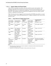
... lists the power states supported by battery or external source. sleeping state G1 - working state. S5 - D3 - Notes: 1. Intel Desktop Board D875PBZ Technical Product Specification 1.12.1.1 System States and Power States Under ACPI, the operating system directs all system and device ... turned off . The operating system uses information from the computer. Table 9. Power States and Targeted System Power Global States Sleeping States Processor States Device States Targeted System Power (Note 1) G0 - working C1 - sleeping state G2/G5 G3 - mechanical off AC power ...
... lists the power states supported by battery or external source. sleeping state G1 - working state. S5 - D3 - Notes: 1. Intel Desktop Board D875PBZ Technical Product Specification 1.12.1.1 System States and Power States Under ACPI, the operating system directs all system and device ... turned off . The operating system uses information from the computer. Table 9. Power States and Targeted System Power Global States Sleeping States Processor States Device States Targeted System Power (Note 1) G0 - working C1 - sleeping state G2/G5 G3 - mechanical off AC power ...

Product Specification
Page 44
... about : The location of the fan connectors The signal names of the fan connectors The location of the fan connectors and sensors for a processor fan or active fan heatsink. • Fan is on or off). For information about The power connector locations The power connector signal names The... the processor fan to a chassis fan connector may result in onboard component damage that can adjust the fan speed or switch the fan on or off as needed . • +12 V DC connection for a system or chassis fan. • Fan is off the system power through system control. Intel Desktop ...
... about : The location of the fan connectors The signal names of the fan connectors The location of the fan connectors and sensors for a processor fan or active fan heatsink. • Fan is on or off). For information about The power connector locations The power connector signal names The... the processor fan to a chassis fan connector may result in onboard component damage that can adjust the fan speed or switch the fan on or off as needed . • +12 V DC connection for a system or chassis fan. • Fan is off the system power through system control. Intel Desktop ...

Product Specification
Page 60
... on the Desktop Board D875PBZ. ✏ NOTE This document references back-panel slot numbering with the slot closest to processor location on page 66 illustrates the Desktop Board D875PBZ's PCI slot numbering. 60 Intel Desktop Board D875PBZ Technical Product Specification 2.8.2 Internal I/O Connectors The internal I/O connectors are identified as PCI slot #x, starting with...
... on the Desktop Board D875PBZ. ✏ NOTE This document references back-panel slot numbering with the slot closest to processor location on page 66 illustrates the Desktop Board D875PBZ's PCI slot numbering. 60 Intel Desktop Board D875PBZ Technical Product Specification 2.8.2 Internal I/O Connectors The internal I/O connectors are identified as PCI slot #x, starting with...

Product Specification
Page 63
...B 1 3 12 34 1 C 3 1 3 D 1 3 1 20 11 10 1 G F E Item A B C D E F G Description Rear chassis fan +12 V power connector (ATX12V) Voltage regulator fan Processor fan Main power Front chassis fan Chassis intrusion For more information see: Table 24 Table 25 Table 26 Table 27 Table 28 Table 29 Table... 30 OM15888 Figure 18. Connecting the processor fan to a chassis fan connector. Technical Reference 2.8.2.3 Power and Hardware Control Connectors CAUTION The processor fan must be connected to the processor fan connector, not to a chassis fan connector may result ...
...B 1 3 12 34 1 C 3 1 3 D 1 3 1 20 11 10 1 G F E Item A B C D E F G Description Rear chassis fan +12 V power connector (ATX12V) Voltage regulator fan Processor fan Main power Front chassis fan Chassis intrusion For more information see: Table 24 Table 25 Table 26 Table 27 Table 28 Table 29 Table... 30 OM15888 Figure 18. Connecting the processor fan to a chassis fan connector. Technical Reference 2.8.2.3 Power and Hardware Control Connectors CAUTION The processor fan must be connected to the processor fan connector, not to a chassis fan connector may result ...

Product Specification
Page 64
...information about The power connector The functions of the fan connectors Refer to both the 4-pin and 20-pin power connectors. Processor Fan Connector Pin Signal Name 1 Control 2 +12 V 3 TACH 64 ATX12V power supplies have an additional power lead that provides ...required supplemental power for the Intel Pentium 4 processor. Rear Chassis Fan Connector Pin Signal Name 1 Control 2 +12 V 3 TACH Table 25. The Desktop Board D875PBZ will not boot with the Desktop Board D875PBZ. Intel Desktop Board D875PBZ Technical Product Specification ✏ NOTE...
...information about The power connector The functions of the fan connectors Refer to both the 4-pin and 20-pin power connectors. Processor Fan Connector Pin Signal Name 1 Control 2 +12 V 3 TACH 64 ATX12V power supplies have an additional power lead that provides ...required supplemental power for the Intel Pentium 4 processor. Rear Chassis Fan Connector Pin Signal Name 1 Control 2 +12 V 3 TACH Table 25. The Desktop Board D875PBZ will not boot with the Desktop Board D875PBZ. Intel Desktop Board D875PBZ Technical Product Specification ✏ NOTE...

Product Specification
Page 73
... signals if 6-channel audio (line out signals if 2-channel audio) are routed to configure mode and the computer is powered-up, the BIOS compares the processor version and the microcode version in connectors are removed and this connector is used for the three modes: normal, configure, and recovery. BIOS Setup Configuration...
... signals if 6-channel audio (line out signals if 2-channel audio) are routed to configure mode and the computer is powered-up, the BIOS compares the processor version and the microcode version in connectors are removed and this connector is used for the three modes: normal, configure, and recovery. BIOS Setup Configuration...

Product Specification
Page 77
...D875PBZ (all five expansion slots and the AGP slot filled) must not exceed 12 A. 2.11.3 Fan Connector Current Capability CAUTION The processor fan must be connected to the processor fan connector, not to provide 2 A (average) of +5 V current for each add-in board. Table 40. Fan Connector ...Current Capability Fan Connector Maximum Available Current Processor fan 1000 mA Front chassis fan 600 mA Rear chassis fan 600 mA Voltage regulator fan 1000 mA 77 Table 40 lists the current ...
...D875PBZ (all five expansion slots and the AGP slot filled) must not exceed 12 A. 2.11.3 Fan Connector Current Capability CAUTION The processor fan must be connected to the processor fan connector, not to provide 2 A (average) of +5 V current for each add-in board. Table 40. Fan Connector ...Current Capability Fan Connector Maximum Available Current Processor fan 1000 mA Front chassis fan 600 mA Rear chassis fan 600 mA Voltage regulator fan 1000 mA 77 Table 40 lists the current ...

Product Specification
Page 79
...maintained in a system with adequate thermal performance. The processor voltage regulator area (item A in Figure 27) can reach a temperature of up to the following website: http://developer.intel.com/design/motherbd/cooling.htm All responsibility for Pentium 4 processors operating above 2.80 GHz with this document will ... please refer to 85 °C in Section 2.14. Technical Reference 2.12 Thermal Considerations CAUTION The use of an Intel Pentium 4 processor operating above 2.80 GHz Failure to ensure appropriate airflow may result in some instances, damage to the desktop board. ...
...maintained in a system with adequate thermal performance. The processor voltage regulator area (item A in Figure 27) can reach a temperature of up to the following website: http://developer.intel.com/design/motherbd/cooling.htm All responsibility for Pentium 4 processors operating above 2.80 GHz with this document will ... please refer to 85 °C in Section 2.14. Technical Reference 2.12 Thermal Considerations CAUTION The use of an Intel Pentium 4 processor operating above 2.80 GHz Failure to ensure appropriate airflow may result in some instances, damage to the desktop board. ...

Product Specification
Page 80
... 27 shows the locations of the localized high temperature zones. Item A B C D Description Processor voltage regulator area Processor Intel 82875P MCH Intel 82801ER ICH5-R Figure 27. Thermal Considerations for components on the Desktop Board D875PBZ that are important... for Components Component Intel Pentium 4 processor Intel 82875P MCH Intel 82801ER ICH5-R Maximum Case Temperature For processor case temperature, see processor datasheets and processor specification updates 99 oC (under bias) 115 oC (under bias) For information about Intel Pentium 4 processor datasheets and specification...
... 27 shows the locations of the localized high temperature zones. Item A B C D Description Processor voltage regulator area Processor Intel 82875P MCH Intel 82801ER ICH5-R Figure 27. Thermal Considerations for components on the Desktop Board D875PBZ that are important... for Components Component Intel Pentium 4 processor Intel 82875P MCH Intel 82801ER ICH5-R Maximum Case Temperature For processor case temperature, see processor datasheets and processor specification updates 99 oC (under bias) 115 oC (under bias) For information about Intel Pentium 4 processor datasheets and specification...


