
Quick Start Guide
Page 1
ISP2150 2U Rack Server Platform Quick Start Guide A Guide for Technically Qualified Assemblers of Intel® Identified Subassemblies/ Products Before You Begin FCC Declaration of Conformity 4 Cautions and Warnings ...6 Product Regulation Compliance 7 Safety Compliance...7 Electromagnetic Compatibility (EMC 7 ISP2150 Opening ...Installing a Microprocessor...10 Installing Memory...11 Installing a Hard Drive...13 Installing Add-in Cards...14 Installing a Slim-Line CD-ROM Drive 16 Removing a Diskette Drive...17 Re-Installing a Diskette Drive 17 Close the Cover...17 Installing the Front Bracket...
ISP2150 2U Rack Server Platform Quick Start Guide A Guide for Technically Qualified Assemblers of Intel® Identified Subassemblies/ Products Before You Begin FCC Declaration of Conformity 4 Cautions and Warnings ...6 Product Regulation Compliance 7 Safety Compliance...7 Electromagnetic Compatibility (EMC 7 ISP2150 Opening ...Installing a Microprocessor...10 Installing Memory...11 Installing a Hard Drive...13 Installing Add-in Cards...14 Installing a Slim-Line CD-ROM Drive 16 Removing a Diskette Drive...17 Re-Installing a Diskette Drive 17 Close the Cover...17 Installing the Front Bracket...
Quick Start Guide
Page 11
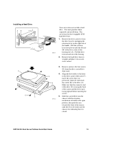
... the drive (A). Installing a Hard Drive AB E D C OM09317 Your server does not include a hard drive. Remove the hard drive from its wrapper and place it is facing upward before inserting the screws. 5. Make sure that it on the right side of the housing slot (A). Pull the drive forward and out of the carrier and the drive top is closed. ISP2150 2U Rack Server Platform...
... the drive (A). Installing a Hard Drive AB E D C OM09317 Your server does not include a hard drive. Remove the hard drive from its wrapper and place it is facing upward before inserting the screws. 5. Make sure that it on the right side of the housing slot (A). Pull the drive forward and out of the carrier and the drive top is closed. ISP2150 2U Rack Server Platform...
Quick Start Guide
Page 23
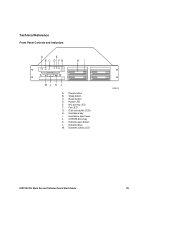
NIC activity LED F. Hard drive bay I. Diskette drive M. CDROM drive bay K. Hard drive eject lever J. Diskette activity LED OM09320 ISP2150 2U Rack Server Platform Quick Start Guide 25 Power LED E. Power button B. Sleep button C. Diskette eject button L. Fail LED G. Disk activity/fail LEDs H. Technical Reference Front Panel Controls and Indicators A E B C D FG HI ML K J A. Reset button D.
NIC activity LED F. Hard drive bay I. Diskette drive M. CDROM drive bay K. Hard drive eject lever J. Diskette activity LED OM09320 ISP2150 2U Rack Server Platform Quick Start Guide 25 Power LED E. Power button B. Sleep button C. Diskette eject button L. Fail LED G. Disk activity/fail LEDs H. Technical Reference Front Panel Controls and Indicators A E B C D FG HI ML K J A. Reset button D.
Quick Start Guide
Page 27
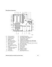
... AA O Z P Y Q XW V U T SR OM08561 A. Battery N. Server Monitor Module (SMM) connector T. Fan connector FAN2B CC. NIC connector FF. Parallel ...ISP2150 2U Rack Server Platform Quick Start Guide 29 Isolated Server Management (ISOL) IMB connector O. Jumper block Q. Fansink connector 2 B. Secondary processor C. Fansink connector 1 D. Main power connector G. ATX aux power connector H. Floppy connector J. IDE connectors K. Front panel connector, 16 pin M. Jumper block P. Fan connector 1 R. Ultra wide SCSI connector S. External Wake on LAN connector U. Hard drive...
... AA O Z P Y Q XW V U T SR OM08561 A. Battery N. Server Monitor Module (SMM) connector T. Fan connector FAN2B CC. NIC connector FF. Parallel ...ISP2150 2U Rack Server Platform Quick Start Guide 29 Isolated Server Management (ISOL) IMB connector O. Jumper block Q. Fansink connector 2 B. Secondary processor C. Fansink connector 1 D. Main power connector G. ATX aux power connector H. Floppy connector J. IDE connectors K. Front panel connector, 16 pin M. Jumper block P. Fan connector 1 R. Ultra wide SCSI connector S. External Wake on LAN connector U. Hard drive...