
Smart Response Technology User Guide
Page 1
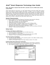
... Response Technology caching is an Intel® Rapid Storage Technology (Intel® RST) caching feature that the SATA controller be set to RAID • Intel Rapid Storage Technology software 10.5 version release or later • Single Hard Disk Drive (HDD) or multiple HDD's in a single ...single drive letter solution; Select the setting for Chipset SATA Mode and change the value to Configuration > SATA Drives 3. Press the F2 key during boot up to configure computer systems with SATA mode set to RAID mode via the system BIOS. Intel ® Smart Response Technology User Guide Note: ...
... Response Technology caching is an Intel® Rapid Storage Technology (Intel® RST) caching feature that the SATA controller be set to RAID • Intel Rapid Storage Technology software 10.5 version release or later • Single Hard Disk Drive (HDD) or multiple HDD's in a single ...single drive letter solution; Select the setting for Chipset SATA Mode and change the value to Configuration > SATA Drives 3. Press the F2 key during boot up to configure computer systems with SATA mode set to RAID mode via the system BIOS. Intel ® Smart Response Technology User Guide Note: ...

Technical Product Specification
Page 7
... 1.1.3 Block Diagram 16 1.2 Online Support 17 1.3 Processor 17 1.3.1 Graphics Subsystem 18 1.4 System Memory 19 1.4.1 Memory Configurations 21 1.5 Intel® Z77 Express Chipset 23 1.5.1 Direct Media Interface (DMI 23 1.5.2 Display Interfaces 23 1.5.3 USB 24 1.5.4 SATA Interfaces 25 1.6 Real-Time Clock Subsystem 26 1.7 Legacy I/O Controller 27 1.7.1 Consumer Infrared (CIR 27 1.8 Audio Subsystem 28 1.8.1 Audio...
... 1.1.3 Block Diagram 16 1.2 Online Support 17 1.3 Processor 17 1.3.1 Graphics Subsystem 18 1.4 System Memory 19 1.4.1 Memory Configurations 21 1.5 Intel® Z77 Express Chipset 23 1.5.1 Direct Media Interface (DMI 23 1.5.2 Display Interfaces 23 1.5.3 USB 24 1.5.4 SATA Interfaces 25 1.6 Real-Time Clock Subsystem 26 1.7 Legacy I/O Controller 27 1.7.1 Consumer Infrared (CIR 27 1.8 Audio Subsystem 28 1.8.1 Audio...

Technical Product Specification
Page 10
...Auxiliary (4-Pin) Fan Headers ..... 55 22. Thermal Considerations for a One-Color Power LED 59 29. Boot Device Menu Options 74 39. SATA Connectors 54 18. Processor Core Power Connector 57 26. Fan Header Current Capability 65 33. Environmental Specifications 68 35. BIOS Setup Program Menu Bar... LED Header 56 25. Front Panel Header 58 28. Front-panel Power LED Blink Codes 80 42. Safety Standards 87 47. Intel Desktop Board DZ77RE-75K Technical Product Specification 13. BIOS Setup Program Function Keys 70 37. Port 80h POST Codes 82 45. IEEE 1394a Header 53 14...
...Auxiliary (4-Pin) Fan Headers ..... 55 22. Thermal Considerations for a One-Color Power LED 59 29. Boot Device Menu Options 74 39. SATA Connectors 54 18. Processor Core Power Connector 57 26. Fan Header Current Capability 65 33. Environmental Specifications 68 35. BIOS Setup Program Menu Bar... LED Header 56 25. Front Panel Header 58 28. Front-panel Power LED Blink Codes 80 42. Safety Standards 87 47. Intel Desktop Board DZ77RE-75K Technical Product Specification 13. BIOS Setup Program Function Keys 70 37. Port 80h POST Codes 82 45. IEEE 1394a Header 53 14...

Technical Product Specification
Page 12
Intel Desktop Board DZ77RE-75K Technical Product Specification Table 1. Feature Summary (continued) Peripheral Interfaces • Eight USB 3.0 ports: ― Four ports implemented with stacked back panel connectors (blue) ― ... through a Marvel 88SE9172 controller (gray) ― One back panel eSATA 6.0 Gb/s port through a Marvel 88SE9172 controller (red) ― Four internal SATA 3.0 Gb/s interfaces through the Intel Z77 Express Chipset with Intel Rapid Storage Technology RAID support (black) • Two IEEE 1394a ports: ― One port via a back panel connector ― One port...
Intel Desktop Board DZ77RE-75K Technical Product Specification Table 1. Feature Summary (continued) Peripheral Interfaces • Eight USB 3.0 ports: ― Four ports implemented with stacked back panel connectors (blue) ― ... through a Marvel 88SE9172 controller (gray) ― One back panel eSATA 6.0 Gb/s port through a Marvel 88SE9172 controller (red) ― Four internal SATA 3.0 Gb/s interfaces through the Intel Z77 Express Chipset with Intel Rapid Storage Technology RAID support (black) • Two IEEE 1394a ports: ― One port via a back panel connector ― One port...
Technical Product Specification
Page 14
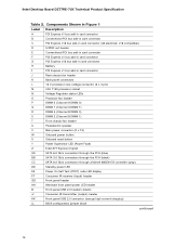
... Express x16 bus add-in card connector H Battery I PCI Express x1 bus add-in card connector (x8 electrical; Intel Desktop Board DZ77RE-75K Technical Product Specification Table 2. Components Shown in Figure 1 Label Description A PCI Express x1 bus add-in card connector...Onboard power button X Onboard reset button Y Power Supervisor LED (Power Fault) Z Intel Z77 Express Chipset AA SATA 6.0 Gb/s connectors through the PCH (blue) BB SATA 3.0 Gb/s connectors through the PCH (black) CC SATA 6.0 Gb/s connectors through a Marvel 88SE9172 controller (gray) DD Standby power LED ...
... Express x16 bus add-in card connector H Battery I PCI Express x1 bus add-in card connector (x8 electrical; Intel Desktop Board DZ77RE-75K Technical Product Specification Table 2. Components Shown in Figure 1 Label Description A PCI Express x1 bus add-in card connector...Onboard power button X Onboard reset button Y Power Supervisor LED (Power Fault) Z Intel Z77 Express Chipset AA SATA 6.0 Gb/s connectors through the PCH (blue) BB SATA 3.0 Gb/s connectors through the PCH (black) CC SATA 6.0 Gb/s connectors through a Marvel 88SE9172 controller (gray) DD Standby power LED ...

Technical Product Specification
Page 23
... and Direct Media Interface (DMI) interconnect provides interfaces to the processor and the display, USB, SATA, LPC, LAN, and PCI Express interfaces. Product Description 1.5 Intel® Z77 Express Chipset Intel Z77 Express Chipset with all ATSC and DVB HDTV standards and supports eight full range channels at 24-bit.../96 kHz audio of the processor and sent to the PCH over Intel FDI and transcodes the data as per the display protocol and driven to the display monitor. 1.5.2.2 High-bandwidth Digital Content Protection (HDCP)...
... and Direct Media Interface (DMI) interconnect provides interfaces to the processor and the display, USB, SATA, LPC, LAN, and PCI Express interfaces. Product Description 1.5 Intel® Z77 Express Chipset Intel Z77 Express Chipset with all ATSC and DVB HDTV standards and supports eight full range channels at 24-bit.../96 kHz audio of the processor and sent to the PCH over Intel FDI and transcodes the data as per the display protocol and driven to the display monitor. 1.5.2.2 High-bandwidth Digital Content Protection (HDCP)...

Technical Product Specification
Page 25
... (gray) • One back panel eSATA 6.0 Gb/s port through a Marvel 88SE9172 controller (red) • Four internal SATA 3.0 Gb/s interfaces through the Intel Z77 Express Chipset with Intel Rapid Storage Technology RAID support (black) The PCH provides independent SATA ports with low-voltage power connectors. data striping • RAID 1 - In native mode, standard PCI Conventional...
... (gray) • One back panel eSATA 6.0 Gb/s port through a Marvel 88SE9172 controller (red) • Four internal SATA 3.0 Gb/s interfaces through the Intel Z77 Express Chipset with Intel Rapid Storage Technology RAID support (black) The PCH provides independent SATA ports with low-voltage power connectors. data striping • RAID 1 - In native mode, standard PCI Conventional...

Technical Product Specification
Page 52
...Express x16 bus add-in card connector H PCI Express x1 bus add-in card connector (x8 electrical; Intel Desktop Board DZ77RE-75K Technical Product Specification Table 12. Component-side Connectors and Headers Shown in Figure 14 Item/callout from Figure 14... x 4 pin) K Processor fan header L Front chassis fan header M Main power connector (2 x 12) N SATA 6.0 Gb/s connectors through the PCH (blue) O SATA 3.0 Gb/s connectors through the PCH (black) P SATA 6.0 Gb/s connectors through a Marvel 88SE9772 controller (gray) Q Consumer IR receiver (input) header R Front panel header...
...Express x16 bus add-in card connector H PCI Express x1 bus add-in card connector (x8 electrical; Intel Desktop Board DZ77RE-75K Technical Product Specification Table 12. Component-side Connectors and Headers Shown in Figure 14 Item/callout from Figure 14... x 4 pin) K Processor fan header L Front chassis fan header M Main power connector (2 x 12) N SATA 6.0 Gb/s connectors through the PCH (blue) O SATA 3.0 Gb/s connectors through the PCH (black) P SATA 6.0 Gb/s connectors through a Marvel 88SE9772 controller (gray) Q Consumer IR receiver (input) header R Front panel header...

Technical Product Specification
Page 54
... Pin Signal Name 1 +5 V DC 2 +5 V DC 3 D− 4 D− 5 D+ 6 D+ 7 Ground 8 Ground 9 KEY (no pin) 10 No Connect Table 19. SATA Connectors Pin Signal Name 1 Ground 2 TXP 3 TXN 4 Ground 5 RXN 6 RXP 7 Ground Table 18. Intel Desktop Board DZ77RE-75K Technical Product Specification Table 17. Front Panel USB 3.0 Connectors Pin Signal Name Description 1 Vbus Power 2 IntA_P1_SSRX− USB3...
... Pin Signal Name 1 +5 V DC 2 +5 V DC 3 D− 4 D− 5 D+ 6 D+ 7 Ground 8 Ground 9 KEY (no pin) 10 No Connect Table 19. SATA Connectors Pin Signal Name 1 Ground 2 TXP 3 TXN 4 Ground 5 RXN 6 RXP 7 Ground Table 18. Intel Desktop Board DZ77RE-75K Technical Product Specification Table 17. Front Panel USB 3.0 Connectors Pin Signal Name Description 1 Vbus Power 2 IntA_P1_SSRX− USB3...

Technical Product Specification
Page 58
... Pin Signal In/ Out Description Hard Drive Activity LED 1 HD_PWR Out Hard disk LED pull-up to an onboard SATA connector. 58 Proper LED function requires a SATA hard drive or optical drive connected to +5 V 3 HDA# Out Hard disk active LED Reset Switch 5 Ground ... Ground Not Connected 10 N/C Description Front panel green LED Front panel yellow LED Power switch Ground Not connected Figure 15. Intel Desktop Board DZ77RE-75K Technical Product Specification 2.2.2.4 Front Panel Header This section describes the functions of the front panel header. Figure 15 is being...
... Pin Signal In/ Out Description Hard Drive Activity LED 1 HD_PWR Out Hard disk LED pull-up to an onboard SATA connector. 58 Proper LED function requires a SATA hard drive or optical drive connected to +5 V 3 HDA# Out Hard disk active LED Reset Switch 5 Ground ... Ground Not Connected 10 N/C Description Front panel green LED Front panel yellow LED Power switch Ground Not connected Figure 15. Intel Desktop Board DZ77RE-75K Technical Product Specification 2.2.2.4 Front Panel Header This section describes the functions of the front panel header. Figure 15 is being...

Technical Product Specification
Page 73
For information about BIOS recovery Refer to http://www.intel.com/support/motherboards/desktop/sb /cs-023360.htm 73 however, if an interruption occurs, the BIOS could be augmented with a custom splash screen. Optical drive connected to the SATA interface Yes USB removable drive (a USB Flash Drive..., for example) Yes USB diskette drive (with the Intel branded logo. This splash screen can and cannot be used for BIOS Recovery Media ...
For information about BIOS recovery Refer to http://www.intel.com/support/motherboards/desktop/sb /cs-023360.htm 73 however, if an interruption occurs, the BIOS could be augmented with a custom splash screen. Optical drive connected to the SATA interface Yes USB removable drive (a USB Flash Drive..., for example) Yes USB diskette drive (with the Intel branded logo. This splash screen can and cannot be used for BIOS Recovery Media ...

Technical Product Specification
Page 75
... delays. • Select an optical drive with parameters such as "power-up to a boot time that the Intel logo screen (or a custom logo splash screen) will automatically not load the option ROM for the SATA controller if no drives are installed in POST. Some monitors initialize and communicate with the BIOS more...
... delays. • Select an optical drive with parameters such as "power-up to a boot time that the Intel logo screen (or a custom logo splash screen) will automatically not load the option ROM for the SATA controller if no drives are installed in POST. Some monitors initialize and communicate with the BIOS more...

Technical Product Specification
Page 82
Intel Desktop Board DZ77RE-75K Technical Product Specification Table 44. Port 80h POST Codes Port 80 Code Progress Code Enumeration ACPI S States 0x00,0x01,0x02,0x03,0x04,0x05 0x10,0x20,... MRC PEI Platform driver 0x11 Set bootmode, GPIO init 0x12 Early chipset register programming including graphics init 0x13 Basic PCH init, discrete device init (1394, SATA) 0x14 LAN init 0x15 0x16 Exit early platform init driver PEI SMBUS SMBUSriver init 0x17 Entry to SMBUS execute read/write 0x18 Exit SMBUS execute...
Intel Desktop Board DZ77RE-75K Technical Product Specification Table 44. Port 80h POST Codes Port 80 Code Progress Code Enumeration ACPI S States 0x00,0x01,0x02,0x03,0x04,0x05 0x10,0x20,... MRC PEI Platform driver 0x11 Set bootmode, GPIO init 0x12 Early chipset register programming including graphics init 0x13 Basic PCH init, discrete device init (1394, SATA) 0x14 LAN init 0x15 0x16 Exit early platform init driver PEI SMBUS SMBUSriver init 0x17 Entry to SMBUS execute read/write 0x18 Exit SMBUS execute...

Technical Product Specification
Page 83
... PCI buses 0x51 0x52 Allocating resources to PCI bus Hot Plug PCI controller initialization USB 0x58 Resetting USB bus 0x59 Reserved for USB ATA/ATAPI/SATA 0x5A Resetting PATA/SATA bus and all devices 0x5B Reserved for ATA continued 83
... PCI buses 0x51 0x52 Allocating resources to PCI bus Hot Plug PCI controller initialization USB 0x58 Resetting USB bus 0x59 Reserved for USB ATA/ATAPI/SATA 0x5A Resetting PATA/SATA bus and all devices 0x5B Reserved for ATA continued 83

Technical Product Specification
Page 86
Intel Desktop Board DZ77RE-75K Technical Product Specification Table 45. Typical Port 80h POST Sequence POST Code Description 21 Initializing a chipset component 22 Reading SPD from memory DIMMs 23 Detecting ... the keyboard 90 Resetting keyboard 94 Clearing keyboard input buffer 95 Keyboard Self Test EB Calling Video BIOS 58 Resetting USB bus 5A Resetting PATA/SATA bus and all devices 92 Detecting the presence of the keyboard 90 Resetting keyboard 94 Clearing keyboard input buffer 5A Resetting PATA...
Intel Desktop Board DZ77RE-75K Technical Product Specification Table 45. Typical Port 80h POST Sequence POST Code Description 21 Initializing a chipset component 22 Reading SPD from memory DIMMs 23 Detecting ... the keyboard 90 Resetting keyboard 94 Clearing keyboard input buffer 95 Keyboard Self Test EB Calling Video BIOS 58 Resetting USB bus 5A Resetting PATA/SATA bus and all devices 92 Detecting the presence of the keyboard 90 Resetting keyboard 94 Clearing keyboard input buffer 5A Resetting PATA...


