
Smart Response Technology User Guide
Page 1
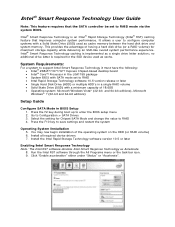
... is required for Chipset SATA Mode and change the value to RAID 4. Go to enter the BIOS setup menu 2. Select the setting for the SSD device used as cache. Intel ® Smart Response Technology User Guide Note: This feature requires that improves computer system performance....the F10 key to configure computer systems with SATA mode set to RAID mode via the system BIOS. It allows a user to save settings and restart the system Operating System Installation 5. Intel® Smart Response Technology is implemented as Accelerate 8. Install all required device drivers 7. Run ...
... is required for Chipset SATA Mode and change the value to RAID 4. Go to enter the BIOS setup menu 2. Select the setting for the SSD device used as cache. Intel ® Smart Response Technology User Guide Note: This feature requires that improves computer system performance....the F10 key to configure computer systems with SATA mode set to RAID mode via the system BIOS. It allows a user to save settings and restart the system Operating System Installation 5. Intel® Smart Response Technology is implemented as Accelerate 8. Install all required device drivers 7. Run ...

Technical Product Specification
Page 2
... in personal computers (PC) for other PC or embedded non-PC applications or other intellectual property rights that relate to only the standard Intel® Desktop Board DZ77BH-55K with BIOS identifier BHZ7710H.86A. NO LICENSE, EXPRESS OR IMPLIED, BY ESTOPPEL OR OTHERWISE, TO ANY INTELLECTUAL PROPERTY RIGHTS IS GRANTED BY THIS DOCUMENT. UNLESS...
... in personal computers (PC) for other PC or embedded non-PC applications or other intellectual property rights that relate to only the standard Intel® Desktop Board DZ77BH-55K with BIOS identifier BHZ7710H.86A. NO LICENSE, EXPRESS OR IMPLIED, BY ESTOPPEL OR OTHERWISE, TO ANY INTELLECTUAL PROPERTY RIGHTS IS GRANTED BY THIS DOCUMENT. UNLESS...

Technical Product Specification
Page 3
...if any, are documented in a separate Specification Update. August 2012 Spec Clarification Updated to the Intel® Desktop Board DZ77BH-55K. iii The AA number is found on a small label on this AA revision consists of Changes...Intel Z77 Express Chipset Stepping C1 S-Spec Numbers SLJC7 Specification Changes or Clarifications Table 1 indicates the Specification Changes or Specification Clarifications that apply to show eSATA through the PCH and not through a Marvell controller. Board Identification Information Basic Desktop Board DZ77BH-55K Identification Information AA Revision BIOS...
...if any, are documented in a separate Specification Update. August 2012 Spec Clarification Updated to the Intel® Desktop Board DZ77BH-55K. iii The AA number is found on a small label on this AA revision consists of Changes...Intel Z77 Express Chipset Stepping C1 S-Spec Numbers SLJC7 Specification Changes or Clarifications Table 1 indicates the Specification Changes or Specification Clarifications that apply to show eSATA through the PCH and not through a Marvell controller. Board Identification Information Basic Desktop Board DZ77BH-55K Identification Information AA Revision BIOS...
Technical Product Specification
Page 5
... abbreviations appear in this level of the BIOS error messages, beep codes, and POST codes Regulatory compliance and battery disposal information Typographical Conventions This section contains information about the Intel Desktop Board DZ77BH-55K and its components to the vendors, system... not intended for the Intel® Desktop Board DZ77BH-55K. It is intended to provide detailed, technical information about the conventions used on the Intel Desktop Board DZ77BH-55K A map of the resources of the Intel Desktop Board The features supported by the BIOS Setup program A description ...
... abbreviations appear in this level of the BIOS error messages, beep codes, and POST codes Regulatory compliance and battery disposal information Typographical Conventions This section contains information about the Intel Desktop Board DZ77BH-55K and its components to the vendors, system... not intended for the Intel® Desktop Board DZ77BH-55K. It is intended to provide detailed, technical information about the conventions used on the Intel Desktop Board DZ77BH-55K A map of the resources of the Intel Desktop Board The features supported by the BIOS Setup program A description ...
Technical Product Specification
Page 8
Intel Desktop Board DZ77BH-55K Technical Product Specification 1.11 Power Management 34 1.11.1 ACPI 34 1.11.2 Hardware Support 37 1.12 Board Status LEDs 42 1.13 Onboard...Considerations 64 2.7 Reliability 67 2.8 Environmental 67 3 Overview of BIOS Features 3.1 Introduction 69 3.2 BIOS Flash Memory Organization 70 3.3 Resource Configuration 70 3.3.1 PCI Autoconfiguration 70 3.4 System Management BIOS (SMBIOS 71 3.5 Legacy USB Support 71 3.6 BIOS Updates 72 3.6.1 Language Support 72 3.6.2 Custom Splash Screen 73 3.7 BIOS Recovery 73 3.8 Boot Options 74 3.8.1 Optical Drive Boot 74...
Intel Desktop Board DZ77BH-55K Technical Product Specification 1.11 Power Management 34 1.11.1 ACPI 34 1.11.2 Hardware Support 37 1.12 Board Status LEDs 42 1.13 Onboard...Considerations 64 2.7 Reliability 67 2.8 Environmental 67 3 Overview of BIOS Features 3.1 Introduction 69 3.2 BIOS Flash Memory Organization 70 3.3 Resource Configuration 70 3.3.1 PCI Autoconfiguration 70 3.4 System Management BIOS (SMBIOS 71 3.5 Legacy USB Support 71 3.6 BIOS Updates 72 3.6.1 Language Support 72 3.6.2 Custom Splash Screen 73 3.7 BIOS Recovery 73 3.8 Boot Options 74 3.8.1 Optical Drive Boot 74...
Technical Product Specification
Page 9
... Diagram for Front Panel Header 56 15. HDMI Port Status Conditions 23 6. Contents 4 Error Messages and Beep Codes 4.1 Speaker 79 4.2 BIOS Beep Codes 79 4.3 Front-panel Power LED Blink Codes 80 4.4 BIOS Error Messages 80 4.5 Port 80h Power On Self Test (POST) Codes 81 5 Regulatory Compliance and Battery Disposal Information 5.1 Regulatory Compliance...
... Diagram for Front Panel Header 56 15. HDMI Port Status Conditions 23 6. Contents 4 Error Messages and Beep Codes 4.1 Speaker 79 4.2 BIOS Beep Codes 79 4.3 Front-panel Power LED Blink Codes 80 4.4 BIOS Error Messages 80 4.5 Port 80h Power On Self Test (POST) Codes 81 5 Regulatory Compliance and Battery Disposal Information 5.1 Regulatory Compliance...

Technical Product Specification
Page 10
... ..... 53 25. Processor Core Power Connector 55 29. States for Intel HD Audio 51 18. Thermal Considerations for Components 66 37. BIOS Setup Program Menu Bar 70 39. Supervisor and User Password Functions 76 43. BIOS Beep Codes 79 44. EMC Regulations 91 51. Power States and...IEEE 1394a Header 51 17. Dual-Port Front Panel USB 2.0 Headers 52 22. States for BIOS Recovery 73 41. AccepDrives/Media Types for a Two-Color Power LED 57 33. Intel Desktop Board DZ77BH-55K Technical Product Specification 7. Port 80h POST Code Ranges 81 47. Audio Jack Support 28 9....
... ..... 53 25. Processor Core Power Connector 55 29. States for Intel HD Audio 51 18. Thermal Considerations for Components 66 37. BIOS Setup Program Menu Bar 70 39. Supervisor and User Password Functions 76 43. BIOS Beep Codes 79 44. EMC Regulations 91 51. Power States and...IEEE 1394a Header 51 17. Dual-Port Front Panel USB 2.0 Headers 52 22. States for BIOS Recovery 73 41. AccepDrives/Media Types for a Two-Color Power LED 57 33. Intel Desktop Board DZ77BH-55K Technical Product Specification 7. Port 80h POST Code Ranges 81 47. Audio Jack Support 28 9....
Technical Product Specification
Page 12
Intel Desktop Board DZ77BH-55K Technical Product Specification Table 2. Feature Summary (continued) Peripheral Interfaces BIOS • Six USB 3.0 ports: ― Four ports implemented with stacked back panel connectors (blue) ― Two ports implemented through one dual-port ...• Two IEEE 1394a ports: ― One port via a back panel connector ― One port via a front-panel header (blue) • Intel® BIOS resident in the SPI Flash device • Support for Advanced Configuration and Power Interface (ACPI), Plug and Play, and SMBIOS Instantly Available PC Technology LAN...
Intel Desktop Board DZ77BH-55K Technical Product Specification Table 2. Feature Summary (continued) Peripheral Interfaces BIOS • Six USB 3.0 ports: ― Four ports implemented with stacked back panel connectors (blue) ― Two ports implemented through one dual-port ...• Two IEEE 1394a ports: ― One port via a back panel connector ― One port via a front-panel header (blue) • Intel® BIOS resident in the SPI Flash device • Support for Advanced Configuration and Power Interface (ACPI), Plug and Play, and SMBIOS Instantly Available PC Technology LAN...

Technical Product Specification
Page 15
Components Shown in Figure 1 (continued) Label Description MM BIOS configuration jumper block NN S/PDIF out header OO Board status LEDs PP Auxiliary fan header QQ IEEE 1394a front panel header 15 Product Description Table 3.
Components Shown in Figure 1 (continued) Label Description MM BIOS configuration jumper block NN S/PDIF out header OO Board status LEDs PP Auxiliary fan header QQ IEEE 1394a front panel header 15 Product Description Table 3.

Technical Product Specification
Page 17
... processors. NOTE This board has specific requirements for the Intel http://ark.intel.com Desktop Board DZ77BH-55K Supported processors Chipset information BIOS and driver updates Tested memory Integration information http://processormatch.intel.com http://www.intel.com/products/desktop/chipsets/index.htm http://downloadcenter.intel.com http://www.intel.com/support/motherboards/desktop/sb/CS025414.htm http://www...
... processors. NOTE This board has specific requirements for the Intel http://ark.intel.com Desktop Board DZ77BH-55K Supported processors Chipset information BIOS and driver updates Tested memory Integration information http://processormatch.intel.com http://www.intel.com/products/desktop/chipsets/index.htm http://downloadcenter.intel.com http://www.intel.com/support/motherboards/desktop/sb/CS025414.htm http://www...

Technical Product Specification
Page 19
.../s. Refer to correctly configure the memory settings, but performance and reliability may not function under the determined frequency. 19 This allows the BIOS to read the SPD data and program the chipset to support higher performance DDR3 SDRAM DIMMs. • 1.35 V Low Voltage DDR3...memory specifications, the board should be impacted or the DIMMs may be populated with x16 organization are only supported by 3rd generation Intel Core processor family processors • XMP version 1.3 performance profile support for optimum performance. For information about PCI Express technology ...
.../s. Refer to correctly configure the memory settings, but performance and reliability may not function under the determined frequency. 19 This allows the BIOS to read the SPD data and program the chipset to support higher performance DDR3 SDRAM DIMMs. • 1.35 V Low Voltage DDR3...memory specifications, the board should be impacted or the DIMMs may be populated with x16 organization are only supported by 3rd generation Intel Core processor family processors • XMP version 1.3 performance profile support for optimum performance. For information about PCI Express technology ...
Technical Product Specification
Page 23
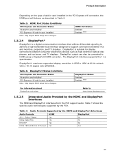
...6. HDMI Port Status Conditions PCI Express x16 Connector Status No add-in card installed PCI Express x16 add-in card installed Note: May require BIOS setup menu changes. DisplayPort Status Enabled Enabled (Note) For information about DisplayPort technology Refer to HDMI using a DisplayPort-HDMI converter. Table 7 ... Status Conditions PCI Express x16 Connector Status No add-in card installed PCI Express x16 add-in card installed Note: May require BIOS setup menu changes. Product Description Depending on the type of add-in card installed in the PCI Express x16 connector, the HDMI...
...6. HDMI Port Status Conditions PCI Express x16 Connector Status No add-in card installed PCI Express x16 add-in card installed Note: May require BIOS setup menu changes. DisplayPort Status Enabled Enabled (Note) For information about DisplayPort technology Refer to HDMI using a DisplayPort-HDMI converter. Table 7 ... Status Conditions PCI Express x16 Connector Status No add-in card installed PCI Express x16 add-in card installed Note: May require BIOS setup menu changes. Product Description Depending on the type of add-in card installed in the PCI Express x16 connector, the HDMI...

Technical Product Specification
Page 26
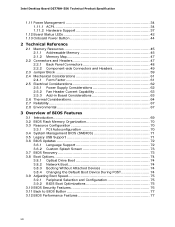
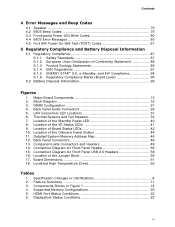
... separate RAID drivers using the F6 switch in the BIOS. distributed parity 1.5.4.2 Intel® Smart Response Technology Intel® Smart Response Technology is a disk caching solution that can provide improved computer system performance with system performance at or near SSD performance levels. Intel Desktop Board DZ77BH-55K Technical Product Specification 1.5.4.1 SATA RAID The board supports the...
... separate RAID drivers using the F6 switch in the BIOS. distributed parity 1.5.4.2 Intel® Smart Response Technology Intel® Smart Response Technology is a disk caching solution that can provide improved computer system performance with system performance at or near SSD performance levels. Intel Desktop Board DZ77BH-55K Technical Product Specification 1.5.4.1 SATA RAID The board supports the...

Technical Product Specification
Page 27
... accurate to control external electronic hardware. When the computer is made up event interface • PCI power management support The BIOS Setup program provides configuration options for PCI systems • Intelligent power management, including a programmable wake-up of a filtered translated...battery. 1.7 Legacy I/O Controller The I /O controller. 1.7.1 Consumer Infrared (CIR) The Consumer Infrared (CIR) feature is not plugged into Intel Desktop Boards for example, the date and time) might not be notified during POST. When the computer is designed to emulate "learned" ...
... accurate to control external electronic hardware. When the computer is made up event interface • PCI power management support The BIOS Setup program provides configuration options for PCI systems • Intelligent power management, including a programmable wake-up of a filtered translated...battery. 1.7 Legacy I/O Controller The I /O controller. 1.7.1 Consumer Infrared (CIR) The Consumer Infrared (CIR) feature is not plugged into Intel Desktop Boards for example, the date and time) might not be notified during POST. When the computer is designed to emulate "learned" ...

Technical Product Specification
Page 37
... full ACPI support. 1.11.2.1 Power Connector ATX12V-compliant power supplies can be set using the Last Power State feature in before power was in the BIOS Setup program's Boot menu. When an ACPI-enabled system receives the correct command, the power supply removes all non-standby voltages. The computer's response can...
... full ACPI support. 1.11.2.1 Power Connector ATX12V-compliant power supplies can be set using the Last Power State feature in before power was in the BIOS Setup program's Boot menu. When an ACPI-enabled system receives the correct command, the power supply removes all non-standby voltages. The computer's response can...

Technical Product Specification
Page 39
....) When signaled by the operating system. 1.11.2.6 PME# Signal Wake-up Support When the PME# signal on the Conventional PCI bus is set in the BIOS). 1.11.2.7 WAKE# Signal Wake-up device or event, the system quickly returns to its last known wake state. Table 12 on PME enabled in the... BIOS, the computer will automatically wake from an ACPI S5 state. 39 The board supports the PCI Bus Power Management Interface Specification. NOTE Wake from USB ...
....) When signaled by the operating system. 1.11.2.6 PME# Signal Wake-up Support When the PME# signal on the Conventional PCI bus is set in the BIOS). 1.11.2.7 WAKE# Signal Wake-up device or event, the system quickly returns to its last known wake state. Table 12 on PME enabled in the... BIOS, the computer will automatically wake from an ACPI S5 state. 39 The board supports the PCI Bus Power Management Interface Specification. NOTE Wake from USB ...

Technical Product Specification
Page 40
...physical damage. If the Power Supervisor detects an out of spec voltage, the following will be added to the BIOS Event Log for each event that takes place until the BIOS Event Log is cleared. 1.11.2.11 +5 V Standby Power Indicator LED The +5 V standby power indicator LED... will activate as a visual cue. 3. A message will happen: 1. Figure 9 shows the location of the Standby Power LED 40 Intel Desktop Board DZ77BH-55K Technical Product Specification 1.11.2.10 Power Supervisor The Power Supervisor actively monitors the input voltages from the power supply and protects the board and...
...physical damage. If the Power Supervisor detects an out of spec voltage, the following will be added to the BIOS Event Log for each event that takes place until the BIOS Event Log is cleared. 1.11.2.11 +5 V Standby Power Indicator LED The +5 V standby power indicator LED... will activate as a visual cue. 3. A message will happen: 1. Figure 9 shows the location of the Standby Power LED 40 Intel Desktop Board DZ77BH-55K Technical Product Specification 1.11.2.10 Power Supervisor The Power Supervisor actively monitors the input voltages from the power supply and protects the board and...

Technical Product Specification
Page 42
... an activity such as processor and voltage regulator overheating and hard drive activity. Refer to monitor the board's progress through the BIOS Power-on Self-Test. Intel Desktop Board DZ77BH-55K Technical Product Specification 1.12 Board Status LEDs The Desktop Board provides eight LEDs that allow you to Table 13 for a description of all...
... an activity such as processor and voltage regulator overheating and hard drive activity. Refer to monitor the board's progress through the BIOS Power-on Self-Test. Intel Desktop Board DZ77BH-55K Technical Product Specification 1.12 Board Status LEDs The Desktop Board provides eight LEDs that allow you to Table 13 for a description of all...

Technical Product Specification
Page 43
.../Callout in Figure 9 LED Name A Hard Drive Activity LED Color Blue B CPU Hot Red C VR Hot Red D Watch Dog Fire / Back to Red BIOS E CPU Initialization Green F Memory Initialization Green G Video Initialization Green H USB Initialization Green I Hard Drive Initialization Green J Option ROM Initialization Green K Operating System ...Start Green Supported Modes On/Off On/Off On/Off On/Off/Flash Control Source Hard drive controller(s) Discrete circuit Discrete circuit BIOS On/Off/Flash On/Off/Flash On/Off/Flash On/Off/Flash On/Off/Flash On/Off/Flash On/Off/Flash...
.../Callout in Figure 9 LED Name A Hard Drive Activity LED Color Blue B CPU Hot Red C VR Hot Red D Watch Dog Fire / Back to Red BIOS E CPU Initialization Green F Memory Initialization Green G Video Initialization Green H USB Initialization Green I Hard Drive Initialization Green J Option ROM Initialization Green K Operating System ...Start Green Supported Modes On/Off On/Off On/Off On/Off/Flash Control Source Hard drive controller(s) Discrete circuit Discrete circuit BIOS On/Off/Flash On/Off/Flash On/Off/Flash On/Off/Flash On/Off/Flash On/Off/Flash On/Off/Flash...

Technical Product Specification
Page 45
... provides the capability to use all of DRAM (total system memory). Figure 11 shows a schematic of system addresses. 45 These functions include the following: • BIOS/SPI Flash device (32 Mb) • Local APIC (19 MB) • Direct Media Interface (40 MB) • PCI Express configuration space (256 MB) • PCH...-mapped I/O that has 32 GB of system memory installed, it is allocated for Conventional PCI and PCI Express add-in cards, PCI Express configuration space, BIOS (SPI Flash device), and chipset overhead resides above the 4 GB boundary.
... provides the capability to use all of DRAM (total system memory). Figure 11 shows a schematic of system addresses. 45 These functions include the following: • BIOS/SPI Flash device (32 Mb) • Local APIC (19 MB) • Direct Media Interface (40 MB) • PCI Express configuration space (256 MB) • PCH...-mapped I/O that has 32 GB of system memory installed, it is allocated for Conventional PCI and PCI Express add-in cards, PCI Express configuration space, BIOS (SPI Flash device), and chipset overhead resides above the 4 GB boundary.


