
Product Guide
Page 5
Contents 1 Desktop Board Features Supported Operating Systems 11 Desktop Board Components 12 Processor ...14 Main Memory...15 Intel® Z68 Express Chipset 16 Intel® Rapid Storage Technology 16 Intel® Smart Response Technology 16 Audio Subsystem 16 LAN Subsystem 17 USB Support ...18 SATA Support...18 SATA RAID 19 Legacy I/O ...19 Expandability...19 Bluetooth...
Contents 1 Desktop Board Features Supported Operating Systems 11 Desktop Board Components 12 Processor ...14 Main Memory...15 Intel® Z68 Express Chipset 16 Intel® Rapid Storage Technology 16 Intel® Smart Response Technology 16 Audio Subsystem 16 LAN Subsystem 17 USB Support ...18 SATA Support...18 SATA RAID 19 Legacy I/O ...19 Expandability...19 Bluetooth...
Product Guide
Page 6
Intel Desktop Board DZ68BC Product Guide 2 Installing and Replacing Desktop Board Components Before You Begin 31 ... Connecting the Processor Fan Heat Sink Cable 39 Removing the Processor 39 Installing and Removing System Memory 40 Guidelines for Dual Channel Memory Configuration 40 Two or Four DIMMs 40 Three DIMMs 41 Installing DIMMs 42 Removing DIMMs 44... PCI Express Graphics Cards 46 Connecting SATA Cables 48 Connecting to the Internal Headers and Connectors 49 Front Panel Intel HD Audio Header 50 S/PDIF Header 50 IEEE 1394a Header 50 Chassis Intrusion Header 51 Consumer IR (CIR)...
Intel Desktop Board DZ68BC Product Guide 2 Installing and Replacing Desktop Board Components Before You Begin 31 ... Connecting the Processor Fan Heat Sink Cable 39 Removing the Processor 39 Installing and Removing System Memory 40 Guidelines for Dual Channel Memory Configuration 40 Two or Four DIMMs 40 Three DIMMs 41 Installing DIMMs 42 Removing DIMMs 44... PCI Express Graphics Cards 46 Connecting SATA Cables 48 Connecting to the Internal Headers and Connectors 49 Front Panel Intel HD Audio Header 50 S/PDIF Header 50 IEEE 1394a Header 50 Chassis Intrusion Header 51 Consumer IR (CIR)...
Product Guide
Page 7
...11. Install the Processor 37 13. Example Dual Channel Memory Configuration with Two DIMMs 40 16. Installing Linked PCI Express Graphics Cards 47 23. Intel Desktop Board DZ68BC Components 12 2. Onboard Power and Reset Buttons 27 6. Intel Desktop Board DZ68BC Mounting Screw Hole Locations 34 9. Internal Headers and ...in Place 38 14. Connecting the Processor Fan Heat Sink Power Cable to BIOS Button 22 4. Example Dual Channel Memory Configuration with Three DIMMs 41 18. Example Dual Channel Memory Configuration with Four DIMMs 41 17. Installing a DIMM 43 20.
...11. Install the Processor 37 13. Example Dual Channel Memory Configuration with Two DIMMs 40 16. Installing Linked PCI Express Graphics Cards 47 23. Intel Desktop Board DZ68BC Components 12 2. Onboard Power and Reset Buttons 27 6. Intel Desktop Board DZ68BC Mounting Screw Hole Locations 34 9. Internal Headers and ...in Place 38 14. Connecting the Processor Fan Heat Sink Power Cable to BIOS Button 22 4. Example Dual Channel Memory Configuration with Three DIMMs 41 18. Example Dual Channel Memory Configuration with Four DIMMs 41 17. Installing a DIMM 43 20.
Product Guide
Page 9
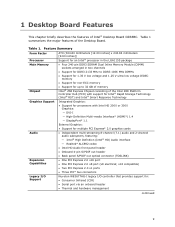
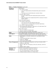
...V ultra low voltage JEDEC memory • Support for non-ECC memory • Support for up to 32 GB of memory Intel® Z68 Express Chipset consisting of the Intel Z68 Platform Controller Hub (PCH) with support for Intel® Rapid Storage Technology (Intel® RST) and Intel® Smart Response Technology ... (CIR) • Serial port via an onboard header • Thermal and hardware management continued 9 Table 1 summarizes the major features of Intel® Desktop Board DZ68BC. Table 1. 1 Desktop Board Features This chapter briefly describes the features of the Desktop Board.
...V ultra low voltage JEDEC memory • Support for non-ECC memory • Support for up to 32 GB of memory Intel® Z68 Express Chipset consisting of the Intel Z68 Platform Controller Hub (PCH) with support for Intel® Rapid Storage Technology (Intel® RST) and Intel® Smart Response Technology ... (CIR) • Serial port via an onboard header • Thermal and hardware management continued 9 Table 1 summarizes the major features of Intel® Desktop Board DZ68BC. Table 1. 1 Desktop Board Features This chapter briefly describes the features of the Desktop Board.
Product Guide
Page 10
Intel Desktop Board DZ68BC Product Guide Table 1. Feature Summary (continued) Peripheral Interfaces USB Support: • Four USB 3.0 ports: ― Two ports implemented with stacked back panel connectors (blue) ―... Mb/s) Ethernet LAN controller including an RJ-45 back panel connector with integrated status LEDs • Intel® Platform Innovation Framework for extensible firmware interface • 32 Mb symmetrical flash memory device • Support for SMBIOS • Intel® Express BIOS Update • Support for Advanced Configuration and Power Interface (ACPI) • ...
Intel Desktop Board DZ68BC Product Guide Table 1. Feature Summary (continued) Peripheral Interfaces USB Support: • Four USB 3.0 ports: ― Two ports implemented with stacked back panel connectors (blue) ―... Mb/s) Ethernet LAN controller including an RJ-45 back panel connector with integrated status LEDs • Intel® Platform Innovation Framework for extensible firmware interface • 32 Mb symmetrical flash memory device • Support for SMBIOS • Intel® Express BIOS Update • Support for Advanced Configuration and Power Interface (ACPI) • ...
Product Guide
Page 15
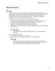
...structure. These operating systems will report less than 1.65 V may damage the processor. • Non-ECC DDR3 memory • Serial Presence Detect (SPD) memory only • Up to 32 GB maximum total system memory using 8 GB DIMMs NOTE 32-bit operating systems are limited to a maximum of 4 GB of... resources. 15 The BIOS will see a notification to this effect on the screen at power up. Desktop Board Features Main Memory NOTE To be fully compliant with all applicable Intel ® SDRAM memory specifications, the board should be populated with a voltage rating higher than 4 GB because of the...
...structure. These operating systems will report less than 1.65 V may damage the processor. • Non-ECC DDR3 memory • Serial Presence Detect (SPD) memory only • Up to 32 GB maximum total system memory using 8 GB DIMMs NOTE 32-bit operating systems are limited to a maximum of 4 GB of... resources. 15 The BIOS will see a notification to this effect on the screen at power up. Desktop Board Features Main Memory NOTE To be fully compliant with all applicable Intel ® SDRAM memory specifications, the board should be populated with a voltage rating higher than 4 GB because of the...
Product Guide
Page 25
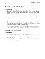
...shown in Figure 4, is lit when there is standby power still present on the front panel, the sleep state is still present at the memory module sockets and the PCI Express connector. 25 If the computer has a dual-colored power LED on the board even when the computer appears ... supply capacity, the Desktop Board may lose register settings stored in the S3 sleep state, the computer will appear to wake the computer. While in memory. Power supplies used to be capable of delivering adequate +5 V standby current. Failure to enter the ACPI S3 (Suspend-toRAM) sleep state. When signaled...
...shown in Figure 4, is lit when there is standby power still present on the front panel, the sleep state is still present at the memory module sockets and the PCI Express connector. 25 If the computer has a dual-colored power LED on the board even when the computer appears ... supply capacity, the Desktop Board may lose register settings stored in the S3 sleep state, the computer will appear to wake the computer. While in memory. Power supplies used to be capable of delivering adequate +5 V standby current. Failure to enter the ACPI S3 (Suspend-toRAM) sleep state. When signaled...
Product Guide
Page 27
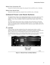
To turn the computer on the board. The Power button stays lit when there is still present at the memory module sockets and the PCI bus connectors. For example, when this button is lit, standby power is standby power still present on or off. This ...
To turn the computer on the board. The Power button stays lit when there is still present at the memory module sockets and the PCI bus connectors. For example, when this button is lit, standby power is standby power still present on or off. This ...
Product Guide
Page 28
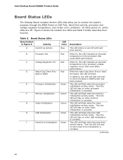
...Activity A Hard Drive Activity B Processor Hot C Voltage Regulator Hot D Watch Dog Timer Fire/ Back to BIOS E Processor Initialization F Memory Initialization G Video Initialization H USB Initialization I Hard Drive Initialization LED Color Blue Red Red Red Green Green Green Green Green Description This LED... light and stay on when memory initialization is complete. Then the LED will flash when the hard drive activity starts. Figure 6 shows the location the LEDs and Table 5 briefly describes their function. Intel Desktop Board DZ68BC Product Guide Board Status LEDs The...
...Activity A Hard Drive Activity B Processor Hot C Voltage Regulator Hot D Watch Dog Timer Fire/ Back to BIOS E Processor Initialization F Memory Initialization G Video Initialization H USB Initialization I Hard Drive Initialization LED Color Blue Red Red Red Green Green Green Green Green Description This LED... light and stay on when memory initialization is complete. Then the LED will flash when the hard drive activity starts. Figure 6 shows the location the LEDs and Table 5 briefly describes their function. Intel Desktop Board DZ68BC Product Guide Board Status LEDs The...
Product Guide
Page 31
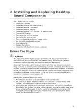
... chapter tells you how to: • Install the I/O shield • Install and remove the Desktop Board • Install and remove a processor • Install and remove memory • Install and remove a PCI Express x16 graphics card • Connect SATA cables • Connect to the internal headers • Connect to operate even though...
... chapter tells you how to: • Install the I/O shield • Install and remove the Desktop Board • Install and remove a processor • Install and remove memory • Install and remove a PCI Express x16 graphics card • Connect SATA cables • Connect to the internal headers • Connect to operate even though...
Product Guide
Page 40
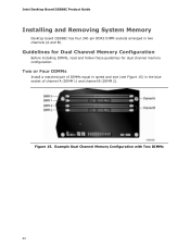
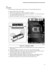
Two or Four DIMMs Install a matched pair of DIMMs equal in speed and size (see Figure 15) in two channels (A and B). Figure 15. Example Dual Channel Memory Configuration with Two DIMMs 40 Intel Desktop Board DZ68BC Product Guide Installing and Removing System Memory Desktop board DZ68BC has four 240-pin DDR3 DIMM sockets arranged in the blue socket of channel A (DIMM 1) and channel B (DIMM 2). Guidelines for Dual Channel Memory Configuration Before installing DIMMs, read and follow these guidelines for dual channel memory configuration.
Two or Four DIMMs Install a matched pair of DIMMs equal in speed and size (see Figure 15) in two channels (A and B). Figure 15. Example Dual Channel Memory Configuration with Two DIMMs 40 Intel Desktop Board DZ68BC Product Guide Installing and Removing System Memory Desktop board DZ68BC has four 240-pin DDR3 DIMM sockets arranged in the blue socket of channel A (DIMM 1) and channel B (DIMM 2). Guidelines for Dual Channel Memory Configuration Before installing DIMMs, read and follow these guidelines for dual channel memory configuration.
Product Guide
Page 41
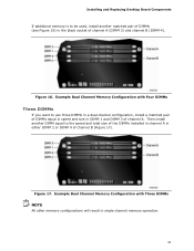
... channel A in either DIMM 2 or DIMM 4 of channel B (Figure 17). Example Dual Channel Memory Configuration with Three DIMMs NOTE All other memory configurations will result in single channel memory operation. 41 Installing and Replacing Desktop Board Components If additional memory is to use three DIMMs in a dual-channel configuration, install a matched pair of DIMMs...
... channel A in either DIMM 2 or DIMM 4 of channel B (Figure 17). Example Dual Channel Memory Configuration with Three DIMMs NOTE All other memory configurations will result in single channel memory operation. 41 Installing and Replacing Desktop Board Components If additional memory is to use three DIMMs in a dual-channel configuration, install a matched pair of DIMMs...
Product Guide
Page 43
... the bottom edge of the DIMM socket(s) are firmly in the blue DIMM sockets first. Installing and Replacing Desktop Board Components NOTE For best memory performance, install memory in place. 9. Align the small notch at either end of the DIMM into place. Replace the computer's cover and reconnect the AC power cord...
... the bottom edge of the DIMM socket(s) are firmly in the blue DIMM sockets first. Installing and Replacing Desktop Board Components NOTE For best memory performance, install memory in place. 9. Align the small notch at either end of the DIMM into place. Replace the computer's cover and reconnect the AC power cord...
Product Guide
Page 60
Intel Desktop Board DZ68BC Product Guide Replacing the Battery A coin-cell battery (CR2032) powers the real-time clock and CMOS memory. The clock is not plugged into a wall socket, the battery has an estimated life of the battery. When the voltage drops below a certain level, the ...
Intel Desktop Board DZ68BC Product Guide Replacing the Battery A coin-cell battery (CR2032) powers the real-time clock and CMOS memory. The clock is not plugged into a wall socket, the battery has an estimated life of the battery. When the voltage drops below a certain level, the ...
Product Guide
Page 67
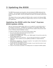
...after the Power-On Self-Test (POST) memory test begins and before the operating system boot begins. Follow the instructions provided in the dialog boxes to the DZ68BC page. 3 Updating the BIOS The BIOS Setup program can be rebooted at http://downloadcenter.intel.com/ 2. This chapter tells you how... BIOS file is useful if you can update the system BIOS while in an automated update utility that combines the functionality of the Intel Flash Memory Update Utility and the ease of use of Windows-based installation wizards. This is included in the Windows environment. Double-click the ...
...after the Power-On Self-Test (POST) memory test begins and before the operating system boot begins. Follow the instructions provided in the dialog boxes to the DZ68BC page. 3 Updating the BIOS The BIOS Setup program can be rebooted at http://downloadcenter.intel.com/ 2. This chapter tells you how... BIOS file is useful if you can update the system BIOS while in an automated update utility that combines the functionality of the Intel Flash Memory Update Utility and the ease of use of Windows-based installation wizards. This is included in the Windows environment. Double-click the ...
Product Guide
Page 68
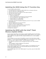
...new version of the target computer. 4. On the DZ68BC page, click on the Intel World Wide Web site Download Center at http://downloadcenter.intel.com. Go to a USB thumb drive. 3. Press the F10 key to complete. 11. The Intel Flash Memory BIOS update file is displayed, press the F7 ...Remove the thumb drive. 12. Download and save and exit. 6. Power the computer on. Updating the BIOS with the Intel® Flash Memory Update Utility You can update to the Intel Desktop Board DZ68BC page on the "BIOS Update" link and then select the Iflash BIOS Update file. 68
...new version of the target computer. 4. On the DZ68BC page, click on the Intel World Wide Web site Download Center at http://downloadcenter.intel.com. Go to a USB thumb drive. 3. Press the F10 key to complete. 11. The Intel Flash Memory BIOS update file is displayed, press the F7 ...Remove the thumb drive. 12. Download and save and exit. 6. Power the computer on. Updating the BIOS with the Intel® Flash Memory Update Utility You can update to the Intel Desktop Board DZ68BC page on the "BIOS Update" link and then select the Iflash BIOS Update file. 68
Product Guide
Page 71
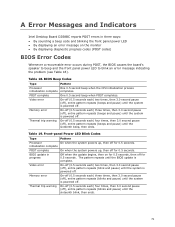
...is powered off. Front-panel Power LED Blink Codes Type Pattern Processor On when the system powers up , then off for 0.5 seconds. Memory error On-off (0.5 seconds each ) two times, then 3.0 second pause (off), entire pattern repeats (beeps and pause) until the system... One 0.5 second beep when POST completes. Memory error On-off (0.5 seconds each ) four times, then 3.0 second pause (off), entire pattern repeats (beeps and pause) until the system is complete. A Error Messages and Indicators Intel Desktop Board DZ68BC reports POST errors in progress Video error Off...
...is powered off. Front-panel Power LED Blink Codes Type Pattern Processor On when the system powers up , then off for 0.5 seconds. Memory error On-off (0.5 seconds each ) two times, then 3.0 second pause (off), entire pattern repeats (beeps and pause) until the system... One 0.5 second beep when POST completes. Memory error On-off (0.5 seconds each ) four times, then 3.0 second pause (off), entire pattern repeats (beeps and pause) until the system is complete. A Error Messages and Indicators Intel Desktop Board DZ68BC reports POST errors in progress Video error Off...
Product Guide
Page 72
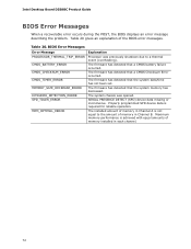
...to a thermal event (overheating). Table 20 gives an explanation of memory installed in Channel B. The installed amount of memory in each channel. 72 The firmware has detected that the system memory has decreased. SERIAL PRESENCE DETECT (SPD) device data missing or ...inconclusive. The firmware has detected that the system date/time has not been set. The firmware has detected that a CMOS Checksum Error occurred. The firmware has detected that a CMOS battery failure occurred. Intel Desktop Board DZ68BC...
...to a thermal event (overheating). Table 20 gives an explanation of memory installed in Channel B. The installed amount of memory in each channel. 72 The firmware has detected that the system memory has decreased. SERIAL PRESENCE DETECT (SPD) device data missing or ...inconclusive. The firmware has detected that the system date/time has not been set. The firmware has detected that a CMOS Checksum Error occurred. The firmware has detected that a CMOS battery failure occurred. Intel Desktop Board DZ68BC...
Product Guide
Page 74
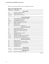
...Entry/Exit to CK505 programming Entry/Exit to PEI overclock programming MEC Memory Detection 21 MRC entry point 23 Reading SPD from memory DIMMs 24 Detecting presence of memory DIMMs 27 Configuring memory 28 Testing memory 29 Exit MRC driver 2A, 2B PEI After MRC Start/finish ...programming MTRR settings 31, 33, 34 PEIMs/Recovery Recovery has initiate, load, valid continued 74 Table 21. Intel Desktop Board DZ68BC Product ...
...Entry/Exit to CK505 programming Entry/Exit to PEI overclock programming MEC Memory Detection 21 MRC entry point 23 Reading SPD from memory DIMMs 24 Detecting presence of memory DIMMs 27 Configuring memory 28 Testing memory 29 Exit MRC driver 2A, 2B PEI After MRC Start/finish ...programming MTRR settings 31, 33, 34 PEIMs/Recovery Recovery has initiate, load, valid continued 74 Table 21. Intel Desktop Board DZ68BC Product ...
Technical Product Specification
Page 7
... 1.1.1 Feature Summary 11 1.1.2 Board Layout 13 1.1.3 Block Diagram 16 1.2 Legacy Considerations 17 1.3 Online Support 17 1.4 Processor 17 1.4.1 PCI Express x16 Graphics 18 1.5 System Memory 18 1.5.1 Memory Configurations 20 1.6 Intel® Z68 Express Chipset 22 1.6.1 USB 22 1.6.2 SATA Interfaces 23 1.7 Graphics Subsystem 24 1.7.1 Integrated Graphics 24 1.8 Real-Time Clock Subsystem 27 1.9 Legacy I/O Controller 27...
... 1.1.1 Feature Summary 11 1.1.2 Board Layout 13 1.1.3 Block Diagram 16 1.2 Legacy Considerations 17 1.3 Online Support 17 1.4 Processor 17 1.4.1 PCI Express x16 Graphics 18 1.5 System Memory 18 1.5.1 Memory Configurations 20 1.6 Intel® Z68 Express Chipset 22 1.6.1 USB 22 1.6.2 SATA Interfaces 23 1.7 Graphics Subsystem 24 1.7.1 Integrated Graphics 24 1.8 Real-Time Clock Subsystem 27 1.9 Legacy I/O Controller 27...


