

Product Specification
Page 5
Contents 1 Product Description 1.1 Overview 9 1.1.1 Feature Summary 9 1.1.2 Board Layout 11 1.1.3 Block Diagram 13 1.2 Legacy Considerations 14 1.3 Online Support 14 1.4 Processor 14 1.5 Intel® Q67 Express Chipset 15 1.6 System Memory 15 1.6.1 Memory Configurations 16 1.7 Graphics Subsystem 18 1.7.1 Integrated Graphics 18 1.7.2 PCI Express x16 Graphics 19 1.8 USB 19 1.9 SATA Interfaces 20 1.10 Legacy I/O Controller 21 1.10.1 Serial...
Contents 1 Product Description 1.1 Overview 9 1.1.1 Feature Summary 9 1.1.2 Board Layout 11 1.1.3 Block Diagram 13 1.2 Legacy Considerations 14 1.3 Online Support 14 1.4 Processor 14 1.5 Intel® Q67 Express Chipset 15 1.6 System Memory 15 1.6.1 Memory Configurations 16 1.7 Graphics Subsystem 18 1.7.1 Integrated Graphics 18 1.7.2 PCI Express x16 Graphics 19 1.8 USB 19 1.9 SATA Interfaces 20 1.10 Legacy I/O Controller 21 1.10.1 Serial...
Product Specification
Page 7
... Reset Header Signals 56 26. Recommended Power Supply Current Values 58 27. LAN Connector LED Locations 25 6. Connection Diagram for Intel HD Audio 47 14. Supported Memory Configurations 16 4. Wake-up Devices and Events 36 8. Component-side Connectors and Headers Shown in Figure 1 12 3. Front Panel Audio Header for Front Panel USB...
... Reset Header Signals 56 26. Recommended Power Supply Current Values 58 27. LAN Connector LED Locations 25 6. Connection Diagram for Intel HD Audio 47 14. Supported Memory Configurations 16 4. Wake-up Devices and Events 36 8. Component-side Connectors and Headers Shown in Figure 1 12 3. Front Panel Audio Header for Front Panel USB...
Product Specification
Page 9
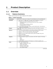
...― Front panel audio header ― Mono speaker header continued 9 Intel® Q67 Express Chipset consisting of the Intel® Q67 Platform Controller Hub (PCH) • Two 240-pin DDR3 SDRAM Dual Inline Memory Module (DIMM) sockets • Support for DDR3 1333 MHz and DDR3 ... thermal solution. See the Note on page 14 for up to 16 GB of system memory with two DIMMs using 4 Gb memory technology • Support for non-ECC memory • Integrated graphics support for processors with Intel® Graphics Technology) ― External graphics interface controller ― Integrated...
...― Front panel audio header ― Mono speaker header continued 9 Intel® Q67 Express Chipset consisting of the Intel® Q67 Platform Controller Hub (PCH) • Two 240-pin DDR3 SDRAM Dual Inline Memory Module (DIMM) sockets • Support for DDR3 1333 MHz and DDR3 ... thermal solution. See the Note on page 14 for up to 16 GB of system memory with two DIMMs using 4 Gb memory technology • Support for non-ECC memory • Integrated graphics support for processors with Intel® Graphics Technology) ― External graphics interface controller ― Integrated...
Product Specification
Page 14
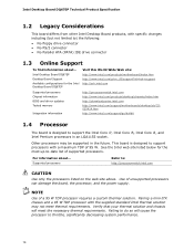
... listed below for the Intel Desktop Board DQ67EP Visit this World Wide Web site: http://www.intel.com/products/motherboard/index.htm http://www.intel.com/p/en_US/support?iid=hdr+support http://ark.intel.com Supported processors Chipset information BIOS and driver updates Tested memory Integration information http://processormatch.intel.com http://www.intel.com/products/desktop/chipsets...
... listed below for the Intel Desktop Board DQ67EP Visit this World Wide Web site: http://www.intel.com/products/motherboard/index.htm http://www.intel.com/p/en_US/support?iid=hdr+support http://ark.intel.com Supported processors Chipset information BIOS and driver updates Tested memory Integration information http://processormatch.intel.com http://www.intel.com/products/desktop/chipsets...

Product Specification
Page 15
... chipset Resources used by the chipset Refer to http://www.intel.com/products/desktop/chipsets/index.htm Chapter 2 1.6 System Memory The board has two DIMM sockets and supports the following memory features: • Two independent memory channels with interleaved mode support • Supports 1.2 V - 1.8 V DIMM memory voltage • Support for information on the total amount of...
... chipset Resources used by the chipset Refer to http://www.intel.com/products/desktop/chipsets/index.htm Chapter 2 1.6 System Memory The board has two DIMM sockets and supports the following memory features: • Two independent memory channels with interleaved mode support • Supports 1.2 V - 1.8 V DIMM memory voltage • Support for information on the total amount of...
Product Specification
Page 16
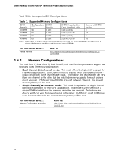
... device width can vary from one channel to : http://support.intel.com/support/motherboards/desktop/sb/CS025414.htm 1.6.1 Memory Configurations The Intel Core i7, Intel Core i5, Intel Core i3, and Intel Pentium processors support the following types of both DIMM channels are ...This mode is installed or the memory capacities are used between channels, the slowest memory timing will be used. This mode is enabled when the installed memory capacities of memory organization: • Dual channel (Interleaved) mode. Intel Desktop Board DQ67EP Technical Product Specification Table 3 lists...
... device width can vary from one channel to : http://support.intel.com/support/motherboards/desktop/sb/CS025414.htm 1.6.1 Memory Configurations The Intel Core i7, Intel Core i5, Intel Core i3, and Intel Pentium processors support the following types of both DIMM channels are ...This mode is installed or the memory capacities are used between channels, the slowest memory timing will be used. This mode is enabled when the installed memory capacities of memory organization: • Dual channel (Interleaved) mode. Intel Desktop Board DQ67EP Technical Product Specification Table 3 lists...

Product Specification
Page 17
Product Description Figure 3 illustrates the memory channel and DIMM configuration. Figure 3. Memory Channel and DIMM Configuration 17
Product Description Figure 3 illustrates the memory channel and DIMM configuration. Figure 3. Memory Channel and DIMM Configuration 17

Product Specification
Page 26
... in , the standby current from the power supply extends the life of the battery. 26 Figure 1 on page 11 shows the location of the battery. Intel Desktop Board DQ67EP Technical Product Specification 1.13 Real-Time Clock Subsystem A coin-cell battery (CR2032) powers the real-time clock and CMOS...
... in , the standby current from the power supply extends the life of the battery. 26 Figure 1 on page 11 shows the location of the battery. Intel Desktop Board DQ67EP Technical Product Specification 1.13 Real-Time Clock Subsystem A coin-cell battery (CR2032) powers the real-time clock and CMOS...

Product Specification
Page 41
...boundary to CPU MTRR cache allocation. 41 2 Technical Reference 2.1 Memory Resources 2.1.1 Addressable Memory The board utilizes 16 GB of the system memory map. Typically the address space that is no overlap of DRAM (total system memory). Check with your operating system vendor. NOTE 32-bit operating ...used when there is allocated for other system critical functions. All installed system memory can be able to reclaim the physical memory overlapped by the memory mapped I /O that has 16 GB of system memory installed, it is dynamically allocated for PCI Express add-in cards, PCI ...
...boundary to CPU MTRR cache allocation. 41 2 Technical Reference 2.1 Memory Resources 2.1.1 Addressable Memory The board utilizes 16 GB of the system memory map. Typically the address space that is no overlap of DRAM (total system memory). Check with your operating system vendor. NOTE 32-bit operating ...used when there is allocated for other system critical functions. All installed system memory can be able to reclaim the physical memory overlapped by the memory mapped I /O that has 16 GB of system memory installed, it is dynamically allocated for PCI Express add-in cards, PCI ...

Product Specification
Page 43
...BIOS Extended BIOS data (movable by the external devices could cause damage to the computer, the power cable, and the external devices themselves. System Memory Map Address Range (decimal) Address Range (hex) 1024 K - 16777216 K 100000 - 3FFFFFFFF 960 K - 1024 K F0000 - Do not...power devices external to the board. EFFFF 800 K - 896 K C8000 - A fault in the load presented by memory manager software) Extended conventional memory Conventional memory 2.2 Connectors and Headers CAUTION Only the following connectors and headers have overcurrent protection: back panel and front panel USB....
...BIOS Extended BIOS data (movable by the external devices could cause damage to the computer, the power cable, and the external devices themselves. System Memory Map Address Range (decimal) Address Range (hex) 1024 K - 16777216 K 100000 - 3FFFFFFFF 960 K - 1024 K F0000 - Do not...power devices external to the board. EFFFF 800 K - 896 K C8000 - A fault in the load presented by memory manager software) Extended conventional memory Conventional memory 2.2 Connectors and Headers CAUTION Only the following connectors and headers have overcurrent protection: back panel and front panel USB....
Product Specification
Page 63
... the BIOS to AHCI. 63 Maintenance Main Configuration Performance Security Power Boot Intel ME Exit NOTE The maintenance menu is displayed only when the board is in a 64 Mbit (8,192 KB) Serial Peripheral Interface Flash Memory (SPI Flash) device which can be updated using a set of utilities.... 3 Overview of BIOS Features 3.1 Introduction The board uses an Intel BIOS that is stored in configure mode. The initial production BIOSs are identified...
... the BIOS to AHCI. 63 Maintenance Main Configuration Performance Security Power Boot Intel ME Exit NOTE The maintenance menu is displayed only when the board is in a 64 Mbit (8,192 KB) Serial Peripheral Interface Flash Memory (SPI Flash) device which can be updated using a set of utilities.... 3 Overview of BIOS Features 3.1 Introduction The board uses an Intel BIOS that is stored in configure mode. The initial production BIOSs are identified...

Product Specification
Page 64
...and displays processor information Displays processor and memory configuration Configures advanced features available through the chipset Configures Memory and Processor overrides Sets passwords and security features Configures power management features Selects boot options Configure Intel ME and Intel AMT settings Saves or discards changes to... field (i.e., date/time) Executes command or selects the submenu Load the default configuration values for menu screens. Intel Desktop Board DQ67EP Technical Product Specification Table 31 lists the BIOS Setup program menu features.
...and displays processor information Displays processor and memory configuration Configures advanced features available through the chipset Configures Memory and Processor overrides Sets passwords and security features Configures power management features Selects boot options Configure Intel ME and Intel AMT settings Saves or discards changes to... field (i.e., date/time) Executes command or selects the submenu Load the default configuration values for menu screens. Intel Desktop Board DQ67EP Technical Product Specification Table 31 lists the BIOS Setup program menu features.

Product Specification
Page 65
...; BIOS data, such as the BIOS revision level • Fixed-system data, such as peripherals, serial numbers, and asset tags • Resource data, such as memory size, cache size, and processor speed • Dynamic data, such as third-party management software to use a USB keyboard to use SMBIOS. After the operating...
...; BIOS data, such as the BIOS revision level • Fixed-system data, such as peripherals, serial numbers, and asset tags • Resource data, such as memory size, cache size, and processor speed • Dynamic data, such as third-party management software to use a USB keyboard to use SMBIOS. After the operating...

Product Specification
Page 66
...(a flash drive or a USB drive), or an optical drive. • Intel® Flash Memory Update Utility, which requires booting from a file on the Intel World Wide Web site: • Intel® Express BIOS Update utility, which are supported in the Windows environment. ...NOTE Review the instructions distributed with the upgrade utility before attempting a BIOS update. Intel Desktop Board DQ67EP...
...(a flash drive or a USB drive), or an optical drive. • Intel® Flash Memory Update Utility, which requires booting from a file on the Intel World Wide Web site: • Intel® Express BIOS Update utility, which are supported in the Windows environment. ...NOTE Review the instructions distributed with the upgrade utility before attempting a BIOS update. Intel Desktop Board DQ67EP...

Product Specification
Page 73
... shut down. For information about The location of the onboard speaker Refer to Figure 1, page 11 4.2 BIOS Beep Codes Whenever a recoverable error occurs during POST. Memory error On-off (1.0 second each) three times, then 2.5-second pause (off), entire pattern repeats (beeps and pause) until the system is ready to Prompt accept...
... shut down. For information about The location of the onboard speaker Refer to Figure 1, page 11 4.2 BIOS Beep Codes Whenever a recoverable error occurs during POST. Memory error On-off (1.0 second each) three times, then 2.5-second pause (off), entire pattern repeats (beeps and pause) until the system is ready to Prompt accept...
Product Specification
Page 74
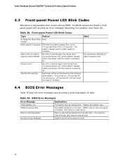
...Table 39. BIOS Error Messages Error Message Explanation CMOS Battery Low The battery may be losing power. Run Setup to boot. 74 Intel Desktop Board DQ67EP Technical Product Specification 4.3 Front-panel Power LED Blink Codes Whenever a recoverable error occurs during POST, the BIOS causes the board's ...4.4 BIOS Error Messages Table 39 lists the error messages and provides a brief description of 16 blinks. Table 38. Video error (no memory was removed, then memory may be bad. On-off (1.0 second each ) two times, then 2.5-second pause (off . Note For processors requiring an add-...
...Table 39. BIOS Error Messages Error Message Explanation CMOS Battery Low The battery may be losing power. Run Setup to boot. 74 Intel Desktop Board DQ67EP Technical Product Specification 4.3 Front-panel Power LED Blink Codes Whenever a recoverable error occurs during POST, the BIOS causes the board's ...4.4 BIOS Error Messages Table 39 lists the error messages and provides a brief description of 16 blinks. Table 38. Video error (no memory was removed, then memory may be bad. On-off (1.0 second each ) two times, then 2.5-second pause (off . Note For processors requiring an add-...
Product Specification
Page 75
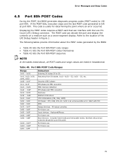
... display the contents on a medium such as a seven-segment display. Resuming from SX states. 0x10 -0x20 - Security (SEC) phase PEI phase pre MRC execution MRC memory detection PEI phase post MRC execution Recovery Platform DXE driver CPU Initialization (PEI, DXE, SMM) I /O port 80h. Start with the Low Pin Count (LPC) Debug...
... display the contents on a medium such as a seven-segment display. Resuming from SX states. 0x10 -0x20 - Security (SEC) phase PEI phase pre MRC execution MRC memory detection PEI phase post MRC execution Recovery Platform DXE driver CPU Initialization (PEI, DXE, SMM) I /O port 80h. Start with the Low Pin Count (LPC) Debug...

Product Specification
Page 76
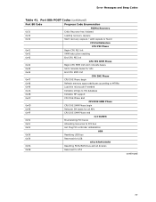
Intel Desktop Board DQ67EP Technical Product Specification Table 41. Port 80h POST Codes Port 80 Code Progress Code Enumeration ACPI S States 0x00,0x01,0x02,0x03,0x04,0x05 Entering S0, ... Programming 0x1B Entry to entry to PEI over-clock programming 0x1C Exit PEI over-clock programming Memory 0x21 0x23 MRC entry point Reading SPD from memory DIMMs 0x24 Detecting presence of memory DIMMs 0x27 Configuring memory 0x28 Testing memory 0x29 Exit MRC driver PEI after MRC 0x2A Start to Program MTRR Settings 0x2B Done Programming...
Intel Desktop Board DQ67EP Technical Product Specification Table 41. Port 80h POST Codes Port 80 Code Progress Code Enumeration ACPI S States 0x00,0x01,0x02,0x03,0x04,0x05 Entering S0, ... Programming 0x1B Entry to entry to PEI over-clock programming 0x1C Exit PEI over-clock programming Memory 0x21 0x23 MRC entry point Reading SPD from memory DIMMs 0x24 Detecting presence of memory DIMMs 0x27 Configuring memory 0x28 Testing memory 0x29 Exit MRC driver PEI after MRC 0x2A Start to Program MTRR Settings 0x2B Done Programming...
Product Specification
Page 77
... Init smm relocate bases 0x45 Smm relocate bases for APs 0x46 End CPU SMM Init CPU DXE Phase 0x47 CPU DXE Phase begin 0x48 Refresh memory space attributes according to MTRRs 0x49 Load the microcode if needed 0x4A Initialize strings to HII database 0x4B Initialize MP support 0x4C CPU DXE Phase...
... Init smm relocate bases 0x45 Smm relocate bases for APs 0x46 End CPU SMM Init CPU DXE Phase 0x47 CPU DXE Phase begin 0x48 Refresh memory space attributes according to MTRRs 0x49 Load the microcode if needed 0x4A Initialize strings to HII database 0x4B Initialize MP support 0x4C CPU DXE Phase...

Product Specification
Page 80
Intel Desktop Board DQ67EP Technical Product Specification Table 42. Typical Port 80h POST Sequence POST Code Description 21 Initializing a chipset component 22 Reading SPD from memory DIMMs 23 Detecting presence of memory DIMMs 25 Configuring memory 28 Testing memory 34 Loading recovery capsule E4 Entered DXE phase 12 Starting ...90 Resetting keyboard 94 Clearing keyboard input buffer 5A Resetting PATA/SATA bus and all devices 28 Testing memory 90 Resetting keyboard 94 Clearing keyboard input buffer E7 Waiting for user input 01 INT 19 00 Ready to boot 80
Intel Desktop Board DQ67EP Technical Product Specification Table 42. Typical Port 80h POST Sequence POST Code Description 21 Initializing a chipset component 22 Reading SPD from memory DIMMs 23 Detecting presence of memory DIMMs 25 Configuring memory 28 Testing memory 34 Loading recovery capsule E4 Entered DXE phase 12 Starting ...90 Resetting keyboard 94 Clearing keyboard input buffer 5A Resetting PATA/SATA bus and all devices 28 Testing memory 90 Resetting keyboard 94 Clearing keyboard input buffer E7 Waiting for user input 01 INT 19 00 Ready to boot 80


