Product Guide
Page 7
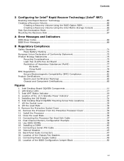
... 22. Location of the +5 V Standby Power Indicator 27 5. LAN Status LEDs 17 3. Remove the Protective Socket Cover 34 10. Dual Channel Memory Configuration Example 38 15. Intel AMT Status Indicator 19 4. Intel Desktop Board DQ45EK Mounting Screw Hole Locations 32 7. Intel Desktop Board DQ45EK Components 11 2. Installing the I/O Shield 31 6. Remove the Processor from the Protective Processor Cover 35 11...
... 22. Location of the +5 V Standby Power Indicator 27 5. LAN Status LEDs 17 3. Remove the Protective Socket Cover 34 10. Dual Channel Memory Configuration Example 38 15. Intel AMT Status Indicator 19 4. Intel Desktop Board DQ45EK Mounting Screw Hole Locations 32 7. Intel Desktop Board DQ45EK Components 11 2. Installing the I/O Shield 31 6. Remove the Processor from the Protective Processor Cover 35 11...

Product Guide
Page 9
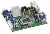
...Desktop Board. Feature Summary Form Factor Processor Main Memory Chipset Graphics Audio Mini-ITX (170.18 millimeters [6.70 inches] x 170.18 millimeters [6.70 inches]) Support for an Intel® processor in the LGA775 package • Two 240-pin, DDR2 1.8 V SDRAM Dual Inline Memory Module (DIMM) sockets...; SATA RAID support via Intel® Matrix Storage Technology (Intel® MST) including support for Intel® Rapid Recover Technology (Intel® RRT) continued 9 Table 1. 1 Desktop Board Features This chapter briefly describes the features of Intel® Desktop Board DQ45EK.
...Desktop Board. Feature Summary Form Factor Processor Main Memory Chipset Graphics Audio Mini-ITX (170.18 millimeters [6.70 inches] x 170.18 millimeters [6.70 inches]) Support for an Intel® processor in the LGA775 package • Two 240-pin, DDR2 1.8 V SDRAM Dual Inline Memory Module (DIMM) sockets...; SATA RAID support via Intel® Matrix Storage Technology (Intel® MST) including support for Intel® Rapid Recover Technology (Intel® RRT) continued 9 Table 1. 1 Desktop Board Features This chapter briefly describes the features of Intel® Desktop Board DQ45EK.
Product Guide
Page 13
... the 12 V (2 x 2 pin) power connector to the Desktop Board may result in damage to the Desktop Board through the LGA775 socket. Go to 4.0 GB utilizing 1 Gb technology • Double-sided DIMMs with x16 organization are not included with DIMMs that support the Serial Presence Detect (SPD) data structure. Intel Desktop Board DQ45EK supports an Intel processor in the LGA775 package.
... the 12 V (2 x 2 pin) power connector to the Desktop Board may result in damage to the Desktop Board through the LGA775 socket. Go to 4.0 GB utilizing 1 Gb technology • Double-sided DIMMs with x16 organization are not included with DIMMs that support the Serial Presence Detect (SPD) data structure. Intel Desktop Board DQ45EK supports an Intel processor in the LGA775 package.
Product Guide
Page 24
...space for key operations and other security critical tasks. Hardware Management Features The hardware management features of Intel Desktop Board DQ45EK enable the board to detect levels above and beyond the capabilities of the monotonic counters is specifically designed to enhance platform... socket to enable Intel Quiet System Technology. • Thermally monitored closed-loop fan control, for all onboard fans, that can adjust fan speed according to maintain its monotonic counters. Intel Desktop Board DQ45EK Product Guide Intel® Trusted Platform Module (Intel® TPM) The Intel TPM...
...space for key operations and other security critical tasks. Hardware Management Features The hardware management features of Intel Desktop Board DQ45EK enable the board to detect levels above and beyond the capabilities of the monotonic counters is specifically designed to enhance platform... socket to enable Intel Quiet System Technology. • Thermally monitored closed-loop fan control, for all onboard fans, that can adjust fan speed according to maintain its monotonic counters. Intel Desktop Board DQ45EK Product Guide Intel® Trusted Platform Module (Intel® TPM) The Intel TPM...
Product Guide
Page 27
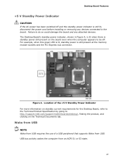
... so could damage the board and any devices connected to http://support.intel.com/support/motherboards/desktop/, finding the product, and clicking on the board even when the computer appears to be off and the standby power indicator is still present at the memory module sockets and the PCI Express bus connector. Desktop Board Features +5 V Standby Power Indicator...
... so could damage the board and any devices connected to http://support.intel.com/support/motherboards/desktop/, finding the product, and clicking on the board even when the computer appears to be off and the standby power indicator is still present at the memory module sockets and the PCI Express bus connector. Desktop Board Features +5 V Standby Power Indicator...

Product Guide
Page 33
Failure to install and remove a processor on the Desktop Board. To install a processor, follow these instructions: 1. the standby power LED should not be lit (see Figure 4 on page 29. 2. Open the socket lever by unplugging the power cord from the socket (Figure 7, A and B). Figure 7. Observe the... page 27). Lift the Socket Lever 33 Installing a Processor CAUTION Before installing or removing the processor, make sure the AC power has been removed by pushing the lever down and away from the computer; Installing and Replacing Desktop Board Components Installing and Removing a...
Failure to install and remove a processor on the Desktop Board. To install a processor, follow these instructions: 1. the standby power LED should not be lit (see Figure 4 on page 29. 2. Open the socket lever by unplugging the power cord from the socket (Figure 7, A and B). Figure 7. Observe the... page 27). Lift the Socket Lever 33 Installing a Processor CAUTION Before installing or removing the processor, make sure the AC power has been removed by pushing the lever down and away from the computer; Installing and Replacing Desktop Board Components Installing and Removing a...

Product Guide
Page 34
Do not touch the socket contacts (Figure 8, B). Lift the Load Plate 4. Do not discard the protective socket cover. Figure 8. Remove the Protective Socket Cover 34 Remove the plastic protective socket cover from the socket. Always replace the socket cover if the processor is removed from the load plate (Figure 9). Intel Desktop Board DQ45EK Product Guide 3. Lift the load plate (Figure 8, A). Figure 9.
Do not touch the socket contacts (Figure 8, B). Lift the Load Plate 4. Do not discard the protective socket cover. Figure 8. Remove the Protective Socket Cover 34 Remove the plastic protective socket cover from the socket. Always replace the socket cover if the processor is removed from the load plate (Figure 9). Intel Desktop Board DQ45EK Product Guide 3. Lift the load plate (Figure 8, A). Figure 9.

Product Guide
Page 35
... thumb and index fingers oriented as shown in the socket. Figure 11. Install the Processor 35 Always replace the processor cover if the processor is removed from the Protective Processor Cover 6. Installing and Replacing Desktop Board Components 5. Hold the processor only at the edges,... being careful not to the socket cutouts (Figure 11, A). Remove the Processor from the socket. Align notches (Figure 11, B) with your fingers align to...
... thumb and index fingers oriented as shown in the socket. Figure 11. Install the Processor 35 Always replace the processor cover if the processor is removed from the Protective Processor Cover 6. Installing and Replacing Desktop Board Components 5. Hold the processor only at the edges,... being careful not to the socket cutouts (Figure 11, A). Remove the Processor from the socket. Align notches (Figure 11, B) with your fingers align to...

Product Guide
Page 36
Pressing down on how to attach the processor fan heat sink to the Desktop Board, refer to the boxed processor manual. 36 Intel Desktop Board DQ45EK Product Guide 7. Close the Load Plate Installing a Processor Fan Heat Sink Intel Desktop Board DQ45EK has mounting holes for a processor fan heat sink. For instructions on the load plate (Figure 12, A), close and engage the socket lever (Figure 12, B). Figure 12.
Pressing down on how to attach the processor fan heat sink to the Desktop Board, refer to the boxed processor manual. 36 Intel Desktop Board DQ45EK Product Guide 7. Close the Load Plate Installing a Processor Fan Heat Sink Intel Desktop Board DQ45EK has mounting holes for a processor fan heat sink. For instructions on the load plate (Figure 12, A), close and engage the socket lever (Figure 12, B). Figure 12.
Product Guide
Page 38
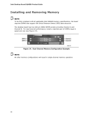
Intel Desktop Board DQ45EK Product Guide Installing and Removing Memory NOTE To be fully compliant with all applicable Intel SDRAM memory specifications, the board requires DIMMs that support the Serial Presence Detect (SPD) data structure. Figure 14. Dual Channel Memory Configuration Example NOTE All other memory configurations will result in speed and size (see Figure 14). For dual-channel performance, install a matched pair of DIMMs equal in single-channel memory operation. 38 The desktop board has two 240-pin DDR2 DIMM sockets providing Channel A and Channel B.
Intel Desktop Board DQ45EK Product Guide Installing and Removing Memory NOTE To be fully compliant with all applicable Intel SDRAM memory specifications, the board requires DIMMs that support the Serial Presence Detect (SPD) data structure. Figure 14. Dual Channel Memory Configuration Example NOTE All other memory configurations will result in speed and size (see Figure 14). For dual-channel performance, install a matched pair of DIMMs equal in single-channel memory operation. 38 The desktop board has two 240-pin DDR2 DIMM sockets providing Channel A and Channel B.

Product Guide
Page 40
... inset in "Before You Begin" on page 29. 2. Align the small notch at either end of the DIMM with the keys in the socket (see Figure 16). Observe the precautions in Figure 16). 40 Turn off the computer and disconnect the AC power cord. 3. Installing a DIMM 4. Holding ...the DIMM by the edges, remove it from its anti-static package. 6. Make sure the clips at the bottom edge of the DIMM socket(s) are pushed outward to the computer. Figure 16. Position the DIMM above the socket. Intel Desktop Board DQ45EK Product Guide To install a DIMM, follow these steps: 1.
... inset in "Before You Begin" on page 29. 2. Align the small notch at either end of the DIMM with the keys in the socket (see Figure 16). Observe the precautions in Figure 16). 40 Turn off the computer and disconnect the AC power cord. 3. Installing a DIMM 4. Holding ...the DIMM by the edges, remove it from its anti-static package. 6. Make sure the clips at the bottom edge of the DIMM socket(s) are pushed outward to the computer. Figure 16. Position the DIMM above the socket. Intel Desktop Board DQ45EK Product Guide To install a DIMM, follow these steps: 1.

Product Guide
Page 41
...are firmly in "Before You Begin" on the top edge of the DIMM into place. Remove the AC power cord from the socket, and store it away from the computer. 4. Installing and Replacing Desktop Board Components 7. Insert the bottom edge of the DIMM until the retaining clips snap into the... socket. 8. When the DIMM is inserted, push down on page 29. 2. Replace the computer's cover and reconnect the AC power cord. 41 Replace...
...are firmly in "Before You Begin" on the top edge of the DIMM into place. Remove the AC power cord from the socket, and store it away from the computer. 4. Installing and Replacing Desktop Board Components 7. Insert the bottom edge of the DIMM until the retaining clips snap into the... socket. 8. When the DIMM is inserted, push down on page 29. 2. Replace the computer's cover and reconnect the AC power cord. 41 Replace...

Product Guide
Page 52
Intel Desktop Board DQ45EK Product Guide 8. Use the arrow keys to save the current values and exit Setup. 10....(CR2032) powers the real-time clock and CMOS memory. The clock is accurate to maintain its monotonic counters. NOTE The Intel TPM uses the onboard coin-cell battery (CR2032) to ± 13 minutes/year at 25 ºC with an equivalent.... When the computer is plugged in accordance with an incorrect type. When the computer is not plugged into a wall socket, the battery has an estimated life of used batteries must be accurate. When the voltage drops below . 13. Figure...
Intel Desktop Board DQ45EK Product Guide 8. Use the arrow keys to save the current values and exit Setup. 10....(CR2032) powers the real-time clock and CMOS memory. The clock is accurate to maintain its monotonic counters. NOTE The Intel TPM uses the onboard coin-cell battery (CR2032) to ± 13 minutes/year at 25 ºC with an equivalent.... When the computer is plugged in accordance with an incorrect type. When the computer is not plugged into a wall socket, the battery has an estimated life of used batteries must be accurate. When the voltage drops below . 13. Figure...

