Product Guide
Page 6
Intel Desktop Board DQ45EK Product Guide 2 Installing and Replacing Desktop Board Components Before You Begin 29 Installation Precautions 30 Prevent Power Supply Overload 30 Observe Safety and Regulatory Requirements 30 Installing the I/O Shield 31 Installing and Removing the Desktop Board 32 Installing and Removing a Processor 33 Installing a Processor 33 ...Jumper 50 Clearing BIOS Security Passwords 51 Replacing the Battery 52 3 Updating the BIOS Updating the BIOS with the Intel® Express BIOS Update Utility 59 Updating the BIOS with the ISO Image BIOS Update File or the Iflash ...
Intel Desktop Board DQ45EK Product Guide 2 Installing and Replacing Desktop Board Components Before You Begin 29 Installation Precautions 30 Prevent Power Supply Overload 30 Observe Safety and Regulatory Requirements 30 Installing the I/O Shield 31 Installing and Removing the Desktop Board 32 Installing and Removing a Processor 33 Installing a Processor 33 ...Jumper 50 Clearing BIOS Security Passwords 51 Replacing the Battery 52 3 Updating the BIOS Updating the BIOS with the Intel® Express BIOS Update Utility 59 Updating the BIOS with the ISO Image BIOS Update File or the Iflash ...
Product Guide
Page 7
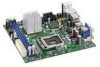
...Shield 31 6. Lift the Load Plate 34 9. Back Panel Audio Connectors 47 20. Location of the Chassis Fan Headers 48 21. Remove the Protective Socket Cover 34 10. Location of the BIOS Configuration Jumper Block 50 vii Connecting Power Supply Cables 49 22. Intel...Dual Channel Memory Configuration Example 38 15. Connecting a Serial ATA Cable 42 18. Lift the Socket Lever 33 8. Intel Desktop Board DQ45EK Components 11 2. Intel Desktop Board DQ45EK Mounting Screw Hole Locations 32 7. Remove the Processor from the Protective Processor Cover 35 11. Installing a DIMM 40...
...Shield 31 6. Lift the Load Plate 34 9. Back Panel Audio Connectors 47 20. Location of the Chassis Fan Headers 48 21. Remove the Protective Socket Cover 34 10. Location of the BIOS Configuration Jumper Block 50 vii Connecting Power Supply Cables 49 22. Intel...Dual Channel Memory Configuration Example 38 15. Connecting a Serial ATA Cable 42 18. Lift the Socket Lever 33 8. Intel Desktop Board DQ45EK Components 11 2. Intel Desktop Board DQ45EK Mounting Screw Hole Locations 32 7. Remove the Processor from the Protective Processor Cover 35 11. Installing a DIMM 40...
Product Guide
Page 21
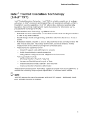
... chipsets that it has correctly invoked the Intel Trusted Execution Technology environment, as well as enable a verified measurement of the software running in use of any other software. • Sealed storage shields encryption keys and other data from attack ...a system to provide assurance that , with appropriate software, enhance the platform security capabilities. Desktop Board Features Intel® Trusted Execution Technology (Intel® TXT) Intel® Trusted Execution Technology (Intel® TXT) is a highly versatile set of hardware extensions to address the increasing frequency...
... chipsets that it has correctly invoked the Intel Trusted Execution Technology environment, as well as enable a verified measurement of the software running in use of any other software. • Sealed storage shields encryption keys and other data from attack ...a system to provide assurance that , with appropriate software, enhance the platform security capabilities. Desktop Board Features Intel® Trusted Execution Technology (Intel® TXT) Intel® Trusted Execution Technology (Intel® TXT) is a highly versatile set of hardware extensions to address the increasing frequency...
Product Guide
Page 24
... beyond the capabilities of the internal Intel TPM data. NOTE The Intel TPM uses the onboard coin-cell battery (CR2032) to shield unencrypted keys and platform authentication information from softwarebased attacks. The board has several hardware management features including the...intrusion detection Fan Speed, Thermal, and Voltage Monitoring and Control The board's fan speed, thermal, and voltage monitoring and control features include the following: • Monitoring of Intel Desktop Board DQ45EK enable the board to thermal conditions. • Fan speed controllers and sensors integrated...
... beyond the capabilities of the internal Intel TPM data. NOTE The Intel TPM uses the onboard coin-cell battery (CR2032) to shield unencrypted keys and platform authentication information from softwarebased attacks. The board has several hardware management features including the...intrusion detection Fan Speed, Thermal, and Voltage Monitoring and Control The board's fan speed, thermal, and voltage monitoring and control features include the following: • Monitoring of Intel Desktop Board DQ45EK enable the board to thermal conditions. • Fan speed controllers and sensors integrated...

Product Guide
Page 29
... computer or perform any of the computer chassis. 29 Perform the procedures described in this chapter. Some circuitry on the board can continue to operate even though the front panel power button is not available, you can provide some ESD protection by... performing any procedures can damage components. If such a station is off. 2 Installing and Replacing Desktop Board Components This chapter tells you how to: • Install the I/O shield • Install and remove the Desktop Board • Install and remove a processor • Install and remove memory • Connect the ...
... computer or perform any of the computer chassis. 29 Perform the procedures described in this chapter. Some circuitry on the board can continue to operate even though the front panel power button is not available, you can provide some ESD protection by... performing any procedures can damage components. If such a station is off. 2 Installing and Replacing Desktop Board Components This chapter tells you how to: • Install the I/O shield • Install and remove the Desktop Board • Install and remove a processor • Install and remove memory • Connect the ...

Product Guide
Page 31
Installing and Replacing Desktop Board Components Installing the I/O Shield The Desktop Board comes with an I /O shield before installing the Desktop Board in the chassis. Place the shield inside the chassis as shown in the chassis, the shield blocks radio frequency transmissions, protects internal components from the chassis supplier. Install the I /O shield. Installing the I/O Shield 31 Press the shield into place so that it fits...
Installing and Replacing Desktop Board Components Installing the I/O Shield The Desktop Board comes with an I /O shield before installing the Desktop Board in the chassis. Place the shield inside the chassis as shown in the chassis, the shield blocks radio frequency transmissions, protects internal components from the chassis supplier. Install the I /O shield. Installing the I/O Shield 31 Press the shield into place so that it fits...

Product Guide
Page 45
Each USB header can be assigned as needed. Use a shielded cable that have an unshielded cable attached to a USB port might not meet FCC Class B requirements, even if no device or a low-speed USB device ... the pin assignments for a full-speed USB device. Serial Port Header See Figure 18, D for the location of the two USB 2.0 headers. Installing and Replacing Desktop Board Components USB 2.0 Headers See Figure 18, C for the location of the serial port header. Table 9. USB Port B Signal Name Power (+5 V) DD+ Ground No Connection NOTE...
Each USB header can be assigned as needed. Use a shielded cable that have an unshielded cable attached to a USB port might not meet FCC Class B requirements, even if no device or a low-speed USB device ... the pin assignments for a full-speed USB device. Serial Port Header See Figure 18, D for the location of the two USB 2.0 headers. Installing and Replacing Desktop Board Components USB 2.0 Headers See Figure 18, C for the location of the serial port header. Table 9. USB Port B Signal Name Power (+5 V) DD+ Ground No Connection NOTE...

Product Guide
Page 81
... following when reading the installation instructions for the host chassis, power supply, and other modules: • Product certifications or lack of certifications • External I/O cable shielding and filtering • Mounting, grounding, and bonding requirements • Keying connectors when mating the wrong connectors could be hazardous If the power supply and other...
... following when reading the installation instructions for the host chassis, power supply, and other modules: • Product certifications or lack of certifications • External I/O cable shielding and filtering • Mounting, grounding, and bonding requirements • Keying connectors when mating the wrong connectors could be hazardous If the power supply and other...