

Product Guide
Page 5
Contents 1 Desktop Board Features Supported Operating Systems 11 Desktop Board Components 12 Online Support 14 Processor ...14 Main Memory...15 Intel® P43 Express Chipset 16 Graphics Support 16 Audio Subsystem 16 Legacy Input/Output (I/O) Controller 17 LAN Subsystem 18 Hi-Speed USB 2.0 Support 19 IEEE ...
Contents 1 Desktop Board Features Supported Operating Systems 11 Desktop Board Components 12 Online Support 14 Processor ...14 Main Memory...15 Intel® P43 Express Chipset 16 Graphics Support 16 Audio Subsystem 16 Legacy Input/Output (I/O) Controller 17 LAN Subsystem 18 Hi-Speed USB 2.0 Support 19 IEEE ...
Product Guide
Page 6
Intel Desktop Board DP43BF Product Guide Installing the I/O Shield 29 Installing and Removing the Desktop Board 30 Installing and Removing a Processor 31 Installing a Processor 31 Installing a Processor Fan Heat Sink 34 Connecting the Processor Fan Heat Sink Cable 35 Removing the Processor 35 Installing and Removing Memory 36 ...Replacing the Battery 55 3 Updating the BIOS Updating the BIOS with the Intel® Express BIOS Update Utility 61 Updating the BIOS with the ISO Image BIOS Update File or the Intel® Flash Memory Update Utility 62 Obtaining the BIOS Update File 62...
Intel Desktop Board DP43BF Product Guide Installing the I/O Shield 29 Installing and Removing the Desktop Board 30 Installing and Removing a Processor 31 Installing a Processor 31 Installing a Processor Fan Heat Sink 34 Connecting the Processor Fan Heat Sink Cable 35 Removing the Processor 35 Installing and Removing Memory 36 ...Replacing the Battery 55 3 Updating the BIOS Updating the BIOS with the Intel® Express BIOS Update Utility 61 Updating the BIOS with the ISO Image BIOS Update File or the Intel® Flash Memory Update Utility 62 Obtaining the BIOS Update File 62...

Product Guide
Page 7
Installing the I/O Shield 29 5. Intel Desktop Board DP43BF Mounting Screw Hole Locations 30 6. Lift the Socket Lever 31 7. Lift the Load Plate 32 8. Install the Processor 33 11. Dual Channel Memory Configuration with Two DIMMs 36 14. Back Panel Audio Connectors 50 24. Removing the Battery 60 28. LAN... 26. Close the Load Plate 34 12. Connecting the IDE Cable 43 21. Remove the Protective Socket Cover 32 9. Internal Headers 45 23. Intel Desktop Board DP43BF China RoHS Material Self Declaration Table 72 vii Connecting the Processor Fan Heat Sink Cable 35 13.
Installing the I/O Shield 29 5. Intel Desktop Board DP43BF Mounting Screw Hole Locations 30 6. Lift the Socket Lever 31 7. Lift the Load Plate 32 8. Install the Processor 33 11. Dual Channel Memory Configuration with Two DIMMs 36 14. Back Panel Audio Connectors 50 24. Removing the Battery 60 28. LAN... 26. Close the Load Plate 34 12. Connecting the IDE Cable 43 21. Remove the Protective Socket Cover 32 9. Internal Headers 45 23. Intel Desktop Board DP43BF China RoHS Material Self Declaration Table 72 vii Connecting the Processor Fan Heat Sink Cable 35 13.
Product Guide
Page 9
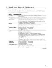
...External Graphics Audio Expansion Capabilities Legacy I/O Support ATX (243.84 millimeters [9.60 inches] x 294.64 millimeters [11.60 inches]) Support for an Intel® processor in the LGA775 package • Four 240-pin, DDR3 SDRAM Dual Inline Memory Module (DIMM) sockets • 1333/1066/800 MHz single ...or dual channel DDR3 SDRAM interface • Support for up to 8 GB of main memory • Intel® P43 Express Chipset consisting of the board. ...
...External Graphics Audio Expansion Capabilities Legacy I/O Support ATX (243.84 millimeters [9.60 inches] x 294.64 millimeters [11.60 inches]) Support for an Intel® processor in the LGA775 package • Four 240-pin, DDR3 SDRAM Dual Inline Memory Module (DIMM) sockets • 1333/1066/800 MHz single ...or dual channel DDR3 SDRAM interface • Support for up to 8 GB of main memory • Intel® P43 Express Chipset consisting of the board. ...

Product Guide
Page 14
... • Available configurations for Intel Desktop Board DP43BF, can be purchased separately. Intel Desktop Board DP43BF supports an Intel processor in the LGA775 package. A list of supported processors for Intel Desktop Board DP43BF http://www.intel.com/products/motherboard/DP43BF/in dex.htm • Supported processors http://processormatch.intel.com • Chipset information http://www.intel.com/products/desktop/chipsets...
... • Available configurations for Intel Desktop Board DP43BF, can be purchased separately. Intel Desktop Board DP43BF supports an Intel processor in the LGA775 package. A list of supported processors for Intel Desktop Board DP43BF http://www.intel.com/products/motherboard/DP43BF/in dex.htm • Supported processors http://processormatch.intel.com • Chipset information http://www.intel.com/products/desktop/chipsets...

Product Guide
Page 16
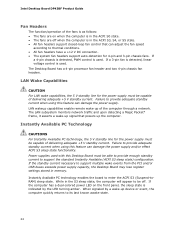
...The onboard audio subsystem consists of the following: • Intel ICH10R I/O controller hub • Realtek ALC888S 10-channel audio codec • Front panel audio header with DMI The MCH component provides interfaces to the processor, memory, PCI Express, and the DMI interconnect. For .../s total). The maximum theoretical bandwidth on the Intel P43 Express Chipset go to http://pcisig.com. Intel Desktop Board DP43BF Product Guide Intel® P43 Express Chipset The Intel P43 Express Chipset consists of the following devices: • Intel P43 Express Chipset Memory Controller Hub (MCH) ...
...The onboard audio subsystem consists of the following: • Intel ICH10R I/O controller hub • Realtek ALC888S 10-channel audio codec • Front panel audio header with DMI The MCH component provides interfaces to the processor, memory, PCI Express, and the DMI interconnect. For .../s total). The maximum theoretical bandwidth on the Intel P43 Express Chipset go to http://pcisig.com. Intel Desktop Board DP43BF Product Guide Intel® P43 Express Chipset The Intel P43 Express Chipset consists of the following devices: • Intel P43 Express Chipset Memory Controller Hub (MCH) ...

Product Guide
Page 19
... throttling. USB 1.1 devices will function normally at USB 1.1 speeds. The PATA interface supports the following modes: • Programmed I/O (PIO): the processor controls data transfer. • 8237-style DMA: DMA offloads the processor, supporting transfer rates of up to 16 MB/s. • Ultra DMA: DMA protocol on the ATA bus supporting host and...
... throttling. USB 1.1 devices will function normally at USB 1.1 speeds. The PATA interface supports the following modes: • Programmed I/O (PIO): the processor controls data transfer. • 8237-style DMA: DMA offloads the processor, supporting transfer rates of up to 16 MB/s. • Ultra DMA: DMA protocol on the ATA bus supporting host and...

Product Guide
Page 22
...• Smart fan control provided by the legacy I /O controller. • Thermally monitored closed-loop fan control, for all Setup options. Intel Desktop Board DP43BF Product Guide Security Passwords The BIOS includes security features that can boot the computer. A supervisor password and a user password can ...be accessed and who can enter either the supervisor password or the user password to thermal conditions. • Two thermal sensors (processor and a remote thermal sensor). 22 The password prompt is displayed before the computer is set , you can boot the computer. If ...
...• Smart fan control provided by the legacy I /O controller. • Thermally monitored closed-loop fan control, for all Setup options. Intel Desktop Board DP43BF Product Guide Security Passwords The BIOS includes security features that can boot the computer. A supervisor password and a user password can ...be accessed and who can enter either the supervisor password or the user password to thermal conditions. • Two thermal sensors (processor and a remote thermal sensor). 22 The password prompt is displayed before the computer is set , you can boot the computer. If ...
Product Guide
Page 24
...standby current necessary to enter the ACPI S3 (Suspend-toRAM) sleep state. When signaled by the LED turning amber. The Desktop Board has a 4-pin processor fan header and two 4-pin chassis fan headers. While in the S3 sleep state, the computer will appear to be able to provide enough standby... current to its last known awake state. 24 Intel Desktop Board DP43BF Product Guide Fan Headers The function/operation of the fans is as follows: • The fans are off . LAN wakeup capabilities...
...standby current necessary to enter the ACPI S3 (Suspend-toRAM) sleep state. When signaled by the LED turning amber. The Desktop Board has a 4-pin processor fan header and two 4-pin chassis fan headers. While in the S3 sleep state, the computer will appear to be able to provide enough standby... current to its last known awake state. 24 Intel Desktop Board DP43BF Product Guide Fan Headers The function/operation of the fans is as follows: • The fans are off . LAN wakeup capabilities...
Product Guide
Page 27
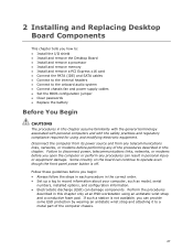
... Replacing Desktop Board Components This chapter tells you how to: • Install the I/O shield • Install and remove the Desktop Board • Install and remove a processor • Install and remove memory • Install and remove a PCI Express x16 card • Connect the PATA (IDE) and SATA cables • Connect to the...
... Replacing Desktop Board Components This chapter tells you how to: • Install the I/O shield • Install and remove the Desktop Board • Install and remove a processor • Install and remove memory • Install and remove a PCI Express x16 card • Connect the PATA (IDE) and SATA cables • Connect to the...

Product Guide
Page 28
...overload the power supply output. For information about regulatory compliance, go to Appendix B on the chassis • Hot components (such as processors, voltage regulators, and heat sinks) • Damage to wires that could cause a short circuit Observe all warnings and cautions that ... the instructions provided by the chassis and module suppliers, you can ensure that your computer meets safety and regulatory requirements. Intel Desktop Board DP43BF Product Guide Installation Precautions When you to refer computer servicing to qualified technical personnel. To avoid overloading the...
...overload the power supply output. For information about regulatory compliance, go to Appendix B on the chassis • Hot components (such as processors, voltage regulators, and heat sinks) • Damage to wires that could cause a short circuit Observe all warnings and cautions that ... the instructions provided by the chassis and module suppliers, you can ensure that your computer meets safety and regulatory requirements. Intel Desktop Board DP43BF Product Guide Installation Precautions When you to refer computer servicing to qualified technical personnel. To avoid overloading the...
Product Guide
Page 31
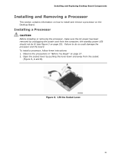
... B). Lift the Socket Lever 31 Figure 6. Installing and Replacing Desktop Board Components Installing and Removing a Processor This section contains information on how to do so could damage the processor and the board. Observe the precautions in "Before You Begin" on page 27. 2. To install... a processor, follow these instructions: 1. Failure to install and remove a processor on page 25). Installing a Processor CAUTION Before installing or removing the processor, make sure the AC power has been removed by pushing the lever down...
... B). Lift the Socket Lever 31 Figure 6. Installing and Replacing Desktop Board Components Installing and Removing a Processor This section contains information on how to do so could damage the processor and the board. Observe the precautions in "Before You Begin" on page 27. 2. To install... a processor, follow these instructions: 1. Failure to install and remove a processor on page 25). Installing a Processor CAUTION Before installing or removing the processor, make sure the AC power has been removed by pushing the lever down...
Product Guide
Page 32
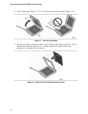
Do not touch the socket contacts (Figure 7, B). Do not discard the protective socket cover. Always replace the socket cover if the processor is removed from the load plate (Figure 8). Figure 7. Remove the Protective Socket Cover 32 Lift the Load Plate 4. Intel Desktop Board DP43BF Product Guide 3. Lift the load plate (Figure 7, A). Figure 8. Remove the plastic protective socket cover from the socket.
Do not touch the socket contacts (Figure 7, B). Do not discard the protective socket cover. Always replace the socket cover if the processor is removed from the load plate (Figure 8). Figure 7. Remove the Protective Socket Cover 32 Lift the Load Plate 4. Intel Desktop Board DP43BF Product Guide 3. Lift the load plate (Figure 7, A). Figure 8. Remove the plastic protective socket cover from the socket.
Product Guide
Page 33
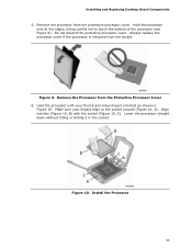
...processor from the Protective Processor Cover 6. Do not discard the protective processor cover. Figure 10. Remove the Processor from the protective processor cover. Always replace the processor cover if the processor is removed from the socket. Hold the processor with the socket (Figure 10, C). Hold the processor... socket. Figure 9. Install the Processor 33 Align notches (Figure 10, B) with your fingers align to touch the bottom of the processor (see Figure 9). Installing and Replacing Desktop Board Components 5. Lower the processor straight down without tilting or sliding...
...processor from the Protective Processor Cover 6. Do not discard the protective processor cover. Figure 10. Remove the Processor from the protective processor cover. Always replace the processor cover if the processor is removed from the socket. Hold the processor with the socket (Figure 10, C). Hold the processor... socket. Figure 9. Install the Processor 33 Align notches (Figure 10, B) with your fingers align to touch the bottom of the processor (see Figure 9). Installing and Replacing Desktop Board Components 5. Lower the processor straight down without tilting or sliding...
Product Guide
Page 34
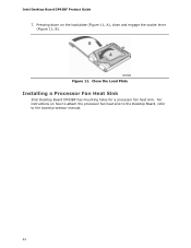
Intel Desktop Board DP43BF Product Guide 7. Pressing down on how to attach the processor fan heat sink to the Desktop Board, refer to the boxed processor manual. 34 For instructions on the load plate (Figure 11, A), close and engage the socket lever (Figure 11, B). Close the Load Plate Installing a Processor Fan Heat Sink Intel Desktop Board DP43BF has mounting holes for a processor fan heat sink. Figure 11.
Intel Desktop Board DP43BF Product Guide 7. Pressing down on how to attach the processor fan heat sink to the Desktop Board, refer to the boxed processor manual. 34 For instructions on the load plate (Figure 11, A), close and engage the socket lever (Figure 11, B). Close the Load Plate Installing a Processor Fan Heat Sink Intel Desktop Board DP43BF has mounting holes for a processor fan heat sink. Figure 11.
Product Guide
Page 35
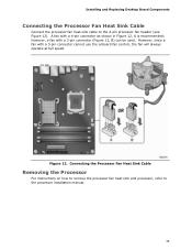
Installing and Replacing Desktop Board Components Connecting the Processor Fan Heat Sink Cable Connect the processor fan heat sink cable to the processor installation manual. 35 however, a fan with a 3-pin connector cannot use the onboard fan control, the fan will always operate at full... a fan with a 3-pin connector (Figure 12, B) can be used. Connecting the Processor Fan Heat Sink Cable Removing the Processor For instructions on how to remove the processor fan heat sink and processor, refer to the 4-pin processor fan header (see Figure 12). Figure 12. A fan with a 4-pin connector as ...
Installing and Replacing Desktop Board Components Connecting the Processor Fan Heat Sink Cable Connect the processor fan heat sink cable to the processor installation manual. 35 however, a fan with a 3-pin connector cannot use the onboard fan control, the fan will always operate at full... a fan with a 3-pin connector (Figure 12, B) can be used. Connecting the Processor Fan Heat Sink Cable Removing the Processor For instructions on how to remove the processor fan heat sink and processor, refer to the 4-pin processor fan header (see Figure 12). Figure 12. A fan with a 4-pin connector as ...
Product Guide
Page 52
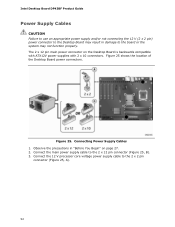
Connect the 12 V processor core voltage power supply cable to the 2 x 12 pin connector (Figure 25, B). 3. Intel Desktop Board DP43BF Product Guide Power Supply Cables CAUTION Failure to use an appropriate power supply and/or not connecting the 12 V (2 x 2 pin) power connector ...
Connect the 12 V processor core voltage power supply cable to the 2 x 12 pin connector (Figure 25, B). 3. Intel Desktop Board DP43BF Product Guide Power Supply Cables CAUTION Failure to use an appropriate power supply and/or not connecting the 12 V (2 x 2 pin) power connector ...
Product Guide
Page 65
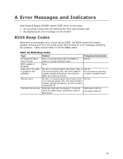
... BIOS update in graphics card On-off (1.0 second each ) for eight beeps followed by system shut down. Table 16. A Error Messages and Indicators Intel Desktop Board DP43BF reports POST errors in two ways: • By sounding a beep code and blinking the front panel power LED • By displaying... recoverable error occurs during POST, the BIOS causes the board's speaker to beep and the front panel power LED to boot. 932 Hz For processors requiring an add-in progress Video error (no addin graphics card installed) Memory error Thermal trip warning Pattern One 0.5 second beep when the BIOS ...
... BIOS update in graphics card On-off (1.0 second each ) for eight beeps followed by system shut down. Table 16. A Error Messages and Indicators Intel Desktop Board DP43BF reports POST errors in two ways: • By sounding a beep code and blinking the front panel power LED • By displaying... recoverable error occurs during POST, the BIOS causes the board's speaker to beep and the front panel power LED to boot. 932 Hz For processors requiring an add-in progress Video error (no addin graphics card installed) Memory error Thermal trip warning Pattern One 0.5 second beep when the BIOS ...
Product Guide
Page 66
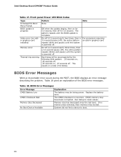
.... BIOS Error Messages When a recoverable error occurs during the POST, the BIOS displays an error message describing the problem. The CMOS checksum is complete. For processors requiring an add-in graphics card On-off (0.5 second each ) two times, then a 3.0-second pause (off for 0.5 second, then off ), the entire pattern repeats (blink... have been corrupted. Front-panel Power LED Blink Codes Type F2 Setup/F10 Boot Menu Prompt BIOS update in a total of the BIOS error messages. Intel Desktop Board DP43BF Product Guide Table 17.
.... BIOS Error Messages When a recoverable error occurs during the POST, the BIOS displays an error message describing the problem. The CMOS checksum is complete. For processors requiring an add-in graphics card On-off (0.5 second each ) two times, then a 3.0-second pause (off for 0.5 second, then off ), the entire pattern repeats (blink... have been corrupted. Front-panel Power LED Blink Codes Type F2 Setup/F10 Boot Menu Prompt BIOS update in a total of the BIOS error messages. Intel Desktop Board DP43BF Product Guide Table 17.
Product Specification
Page 7
Contents 1 Product Description 1.1 Overview 11 1.1.1 Feature Summary 11 1.1.2 Board Layout 13 1.1.3 Block Diagram 15 1.2 Legacy Considerations 16 1.3 Online Support 16 1.4 Processor 17 1.5 System Memory 18 1.5.1 Memory Configurations 19 1.6 Intel® P43 Express Chipset 21 1.6.2 USB 21 1.6.3 ATA Support 22 1.7 Real-Time Clock Subsystem 24 1.8 Legacy I/O Controller 24 1.8.1 Serial Port 24 1.9 Audio Subsystem 25...
Contents 1 Product Description 1.1 Overview 11 1.1.1 Feature Summary 11 1.1.2 Board Layout 13 1.1.3 Block Diagram 15 1.2 Legacy Considerations 16 1.3 Online Support 16 1.4 Processor 17 1.5 System Memory 18 1.5.1 Memory Configurations 19 1.6 Intel® P43 Express Chipset 21 1.6.2 USB 21 1.6.3 ATA Support 22 1.7 Real-Time Clock Subsystem 24 1.8 Legacy I/O Controller 24 1.8.1 Serial Port 24 1.9 Audio Subsystem 25...


