Product Guide
Page 5
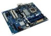
...Desktop Board Features Supported Operating Systems 10 Desktop Board Components 11 Processor ...13 Main Memory...13 Intel® P35 Express Chipset 14 Audio Subsystem 15 Legacy Input/Output (I/O) Controller 15 LAN Subsystem 16 RJ-45 LAN Connector LEDs 16 Hi-Speed USB 2.0 Support 17 Enhanced IDE Interface 17 Serial ATA...18 Serial ATA RAID 18 Intel... ENERGY STAR* Capable 24 Speaker...24 Battery ...24 Real-Time Clock 24 2 Installing and Replacing Desktop Board Components Before You Begin 25 Installation Precautions 26 Prevent Power Supply Overload 26 Observe Safety and Regulatory ...
...Desktop Board Features Supported Operating Systems 10 Desktop Board Components 11 Processor ...13 Main Memory...13 Intel® P35 Express Chipset 14 Audio Subsystem 15 Legacy Input/Output (I/O) Controller 15 LAN Subsystem 16 RJ-45 LAN Connector LEDs 16 Hi-Speed USB 2.0 Support 17 Enhanced IDE Interface 17 Serial ATA...18 Serial ATA RAID 18 Intel... ENERGY STAR* Capable 24 Speaker...24 Battery ...24 Real-Time Clock 24 2 Installing and Replacing Desktop Board Components Before You Begin 25 Installation Precautions 26 Prevent Power Supply Overload 26 Observe Safety and Regulatory ...
Product Guide
Page 6
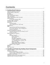
Intel Desktop Board DP35DP Product Guide Installing a Processor 29 Installing the Processor Fan Heat Sink 32 Connecting the Processor Fan Heat Sink Cable 33 Removing the Processor 34 Installing and Removing Memory 34 Guidelines for Dual Channel Memory Configuration 35 Two or Four DIMMs 35 Three DIMMs 36 ... Headers 46 Connecting to the HD Audio Link Header 47 Connecting to the IEEE 1394a Header 47 Installing a Front Panel Audio Solution for Intel® High Definition Audio 47 Connecting to the Consumer IR (CIR) Headers 48 Connecting to the Serial Port Header 49 Connecting to the...
Intel Desktop Board DP35DP Product Guide Installing a Processor 29 Installing the Processor Fan Heat Sink 32 Connecting the Processor Fan Heat Sink Cable 33 Removing the Processor 34 Installing and Removing Memory 34 Guidelines for Dual Channel Memory Configuration 35 Two or Four DIMMs 35 Three DIMMs 36 ... Headers 46 Connecting to the HD Audio Link Header 47 Connecting to the IEEE 1394a Header 47 Installing a Front Panel Audio Solution for Intel® High Definition Audio 47 Connecting to the Consumer IR (CIR) Headers 48 Connecting to the Serial Port Header 49 Connecting to the...
Product Guide
Page 7
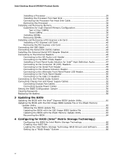
... the Socket Lever 29 7. Back Panel Audio Connectors 51 25. Installing the I/O Shield 27 5. Desktop Board DP35DP Mounting Screw Hole Locations 28 6. Connecting the Processor Fan Heat Sink Cable to the Processor Fan Header ..........33 13. Dual Channel Memory Configuration with Two DIMMs 35 14. Dual Channel Memory ...67 Creating a Recovery Volume 68 Creating a Recovery Volume Using the RAID Option ROM 68 Creating a Recovery Volume Using the Intel Matrix Storage Console 68 Disk Synchronization Mode 69 Mounting the Recovery Disk 69 A Error Messages and Indicators BIOS Beep Codes 71 ...
... the Socket Lever 29 7. Back Panel Audio Connectors 51 25. Installing the I/O Shield 27 5. Desktop Board DP35DP Mounting Screw Hole Locations 28 6. Connecting the Processor Fan Heat Sink Cable to the Processor Fan Header ..........33 13. Dual Channel Memory Configuration with Two DIMMs 35 14. Dual Channel Memory ...67 Creating a Recovery Volume 68 Creating a Recovery Volume Using the RAID Option ROM 68 Creating a Recovery Volume Using the Intel Matrix Storage Console 68 Disk Synchronization Mode 69 Mounting the Recovery Disk 69 A Error Messages and Indicators BIOS Beep Codes 71 ...
Product Guide
Page 9
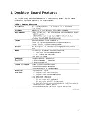
...Memory Chipset Graphics Audio Expansion Capabilities Legacy I/O Support Peripheral Interfaces ATX (320.04 millimeters [11.60 inches] x 243.84 millimeters [9.60 inches]) Support for an Intel® processor in the LGA775 package • Four 240-pin, DDR2 1.8 V (only) SDRAM Dual Inline Memory Module (DIMM) sockets • 800/667 MHz single or...• Up to two IEEE 1394a ports ― One port routed to the back panel ― One port routed to 8 GB of system memory Intel® P35 Express Chipset consisting of Intel® Desktop Board DP35DP. Table 1 summarizes the major features of the...
...Memory Chipset Graphics Audio Expansion Capabilities Legacy I/O Support Peripheral Interfaces ATX (320.04 millimeters [11.60 inches] x 243.84 millimeters [9.60 inches]) Support for an Intel® processor in the LGA775 package • Four 240-pin, DDR2 1.8 V (only) SDRAM Dual Inline Memory Module (DIMM) sockets • 800/667 MHz single or...• Up to two IEEE 1394a ports ― One port routed to the back panel ― One port routed to 8 GB of system memory Intel® P35 Express Chipset consisting of Intel® Desktop Board DP35DP. Table 1 summarizes the major features of the...
Product Guide
Page 13
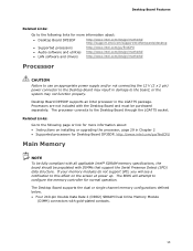
... the following links for more information about : • Desktop Board DP35DP http://www.intel.com/design/motherbd http://support.intel.com/support/motherboards/desktop • Supported processors http://www.intel.com/go /findCPU Main Memory NOTE To be fully compliant with gold-plated contacts. 13 Desktop Board DP35DP supports an Intel processor in damage to the board, or the system may result in the LGA775...
... the following links for more information about : • Desktop Board DP35DP http://www.intel.com/design/motherbd http://support.intel.com/support/motherboards/desktop • Supported processors http://www.intel.com/go /findCPU Main Memory NOTE To be fully compliant with gold-plated contacts. 13 Desktop Board DP35DP supports an Intel processor in damage to the board, or the system may result in the LGA775...
Product Guide
Page 14
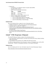
... Express Chipset consists of the following links or pages for more information about the Intel P35 Express Chipset: http://developer.intel.com/products/chipsets/index.htm 14 Intel Desktop Board DP35DP Product Guide • Support for: ⎯ Unbuffered, non-registered single or... Intel P35 Express Chipset Memory Controller Hub (MCH) with DMI interconnect The MCH provides interfaces to the processor, memory, PCI Express bus, and the DMI interconnect. ICH9R is a centralized controller for the board's I /O Controller Hub (ICH9R) with Direct Media Interface (DMI) interconnect • Intel...
... Express Chipset consists of the following links or pages for more information about the Intel P35 Express Chipset: http://developer.intel.com/products/chipsets/index.htm 14 Intel Desktop Board DP35DP Product Guide • Support for: ⎯ Unbuffered, non-registered single or... Intel P35 Express Chipset Memory Controller Hub (MCH) with DMI interconnect The MCH provides interfaces to the processor, memory, PCI Express bus, and the DMI interconnect. ICH9R is a centralized controller for the board's I /O Controller Hub (ICH9R) with Direct Media Interface (DMI) interconnect • Intel...
Product Guide
Page 17
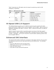
... up and the LAN subsystem is occurring 10 Mb/s data rate 100 Mb/s data rate 1000 Mb/s data rate Hi-Speed USB 2.0 Support The Desktop Board supports up to 12 USB 2.0 ports (six ports routed to the back panel and six ports routed to three internal headers) via the ICH9R. ...The interface supports: • Up to USB 1.1 operation. Enhanced IDE Interface The board's IDE interface handles the exchange of information between the processor and peripheral devices such as CD-ROM drives) • Older PIO Mode devices • Ultra DMA-33 and ATA-66/100...
... up and the LAN subsystem is occurring 10 Mb/s data rate 100 Mb/s data rate 1000 Mb/s data rate Hi-Speed USB 2.0 Support The Desktop Board supports up to 12 USB 2.0 ports (six ports routed to the back panel and six ports routed to three internal headers) via the ICH9R. ...The interface supports: • Up to USB 1.1 operation. Enhanced IDE Interface The board's IDE interface handles the exchange of information between the processor and peripheral devices such as CD-ROM drives) • Older PIO Mode devices • Ultra DMA-33 and ATA-66/100...
Product Guide
Page 20
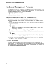
... intrusion header on the chassis that detects if the chassis cover has been removed. Intel Desktop Board DP35DP Product Guide Hardware Management Features The hardware management features of Desktop Board DP35DP enable the board to be compatible with the Wired for all onboard fans, that can adjust fan ... needed Chassis Intrusion The board supports a chassis security feature that can be installed in the Channel A, DIMM 0 socket to enable Intel Quiet System Technology. • Fan speed controllers and sensors integrated into the ICH9R • Thermal sensors in the processor, MCH, and ICH9R,...
... intrusion header on the chassis that detects if the chassis cover has been removed. Intel Desktop Board DP35DP Product Guide Hardware Management Features The hardware management features of Desktop Board DP35DP enable the board to be compatible with the Wired for all onboard fans, that can adjust fan ... needed Chassis Intrusion The board supports a chassis security feature that can be installed in the Channel A, DIMM 0 socket to enable Intel Quiet System Technology. • Fan speed controllers and sensors integrated into the ICH9R • Thermal sensors in the processor, MCH, and ICH9R,...
Product Guide
Page 22
The Desktop Board has a 4-pin processor fan header, and one 4-pin and two 3-pin chassis fan headers. The LAN subsystem...is wired to support multiple wake events from the PCI and/or USB buses exceeds power supply capacity, the Desktop Board may lose register settings stored in the S3 sleep state, the computer will appear to enter the ACPI ... device. • All fan headers support closed-loop fan control that powers up of the computer through a network. Intel Desktop Board DP35DP Product Guide Fan Headers The function/operation of the fans is as needed. • All fan headers have a +12...
The Desktop Board has a 4-pin processor fan header, and one 4-pin and two 3-pin chassis fan headers. The LAN subsystem...is wired to support multiple wake events from the PCI and/or USB buses exceeds power supply capacity, the Desktop Board may lose register settings stored in the S3 sleep state, the computer will appear to enter the ACPI ... device. • All fan headers support closed-loop fan control that powers up of the computer through a network. Intel Desktop Board DP35DP Product Guide Fan Headers The function/operation of the fans is as needed. • All fan headers have a +12...
Product Guide
Page 25
2 Installing and Replacing Desktop Board Components This chapter tells you can provide some ESD protection ... compliance required for using an antistatic wrist strap and a conductive foam pad. Some circuitry on the board can result in this chapter only at an ESD workstation using and modifying electronic equipment. Follow these ...button is not available, you how to: • Install the I/O shield • Install and remove the Desktop Board • Install and remove a processor • Install and remove memory • Install and remove a PCI Express x16 card • Connect ...
2 Installing and Replacing Desktop Board Components This chapter tells you can provide some ESD protection ... compliance required for using an antistatic wrist strap and a conductive foam pad. Some circuitry on the board can result in this chapter only at an ESD workstation using and modifying electronic equipment. Follow these ...button is not available, you how to: • Install the I/O shield • Install and remove the Desktop Board • Install and remove a processor • Install and remove memory • Install and remove a PCI Express x16 card • Connect ...
Product Guide
Page 26
... Hot components (such as processors, voltage regulators, and heat sinks) • Damage to wires that could cause a short circuit Observe all warnings and cautions that instruct you to refer computer servicing to find out how you install and test the Intel Desktop Board, observe all the modules... and associated modules. Observe Safety and Regulatory Requirements Read and adhere the instructions in the installation instructions. Intel Desktop Board DP35DP Product Guide Installation Precautions When you can ensure that your computer meets safety and regulatory requirements.
... Hot components (such as processors, voltage regulators, and heat sinks) • Damage to wires that could cause a short circuit Observe all warnings and cautions that instruct you to refer computer servicing to find out how you install and test the Intel Desktop Board, observe all the modules... and associated modules. Observe Safety and Regulatory Requirements Read and adhere the instructions in the installation instructions. Intel Desktop Board DP35DP Product Guide Installation Precautions When you can ensure that your computer meets safety and regulatory requirements.

Product Guide
Page 29
... LED should not be lit (see Figure 3 on how to install the processor to do so could damage the processor and the board. Installing and Replacing Desktop Board Components Installing and Removing a Processor Instructions on page 23). Installing a Processor CAUTION Before installing or removing the processor, make sure the AC power has been removed by pushing the lever...
... LED should not be lit (see Figure 3 on how to install the processor to do so could damage the processor and the board. Installing and Replacing Desktop Board Components Installing and Removing a Processor Instructions on page 23). Installing a Processor CAUTION Before installing or removing the processor, make sure the AC power has been removed by pushing the lever...

Product Guide
Page 30
Do not touch the socket contacts (Figure 7, B). Figure 7. Intel Desktop Board DP35DP Product Guide 3. Always replace the socket cover if the processor is removed from the load plate (Figure 8). Remove the Protective Socket Cover 30 Figure 8. Do not discard the protective socket cover. Lift the Load Plate 4. Remove the plastic protective socket cover from the socket. Lift the load plate (Figure 7, A).
Do not touch the socket contacts (Figure 7, B). Figure 7. Intel Desktop Board DP35DP Product Guide 3. Always replace the socket cover if the processor is removed from the load plate (Figure 8). Remove the Protective Socket Cover 30 Figure 8. Do not discard the protective socket cover. Lift the Load Plate 4. Remove the plastic protective socket cover from the socket. Lift the load plate (Figure 7, A).

Product Guide
Page 31
Remove the processor from the Protective Processor Cover 6. Hold the processor only at the edges, being careful not to the socket cutouts (Figure 10, A). Figure 9. Figure 10. Hold the processor with the socket (Figure 10, C). Make sure your thumb and index fingers ... the processor (see Figure 9). Remove the Processor from the protective processor cover. Lower the processor straight down without tilting or sliding it in Figure 10. Installing and Replacing Desktop Board Components 5. Install the Processor 31 Always replace the processor cover if the processor is removed...
Remove the processor from the Protective Processor Cover 6. Hold the processor only at the edges, being careful not to the socket cutouts (Figure 10, A). Figure 9. Figure 10. Hold the processor with the socket (Figure 10, C). Make sure your thumb and index fingers ... the processor (see Figure 9). Remove the Processor from the protective processor cover. Lower the processor straight down without tilting or sliding it in Figure 10. Installing and Replacing Desktop Board Components 5. Install the Processor 31 Always replace the processor cover if the processor is removed...
Product Guide
Page 32
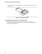
Close the Load Plate Installing the Processor Fan Heat Sink Desktop Board DP35DP has mounting holes for a processor fan heat sink. Figure 11. Intel Desktop Board DP35DP Product Guide 7. Pressing down on how to attach the processor fan heat sink to the Desktop Board, refer to the boxed processor manual. 32 For instructions on the load plate (Figure 11, A), close and engage the socket lever (Figure 11, B).
Close the Load Plate Installing the Processor Fan Heat Sink Desktop Board DP35DP has mounting holes for a processor fan heat sink. Figure 11. Intel Desktop Board DP35DP Product Guide 7. Pressing down on how to attach the processor fan heat sink to the Desktop Board, refer to the boxed processor manual. 32 For instructions on the load plate (Figure 11, A), close and engage the socket lever (Figure 11, B).
Product Guide
Page 33
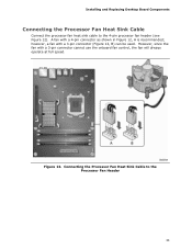
Figure 12. however, a fan with a 4-pin connector as shown in Figure 12, A is recommended; Installing and Replacing Desktop Board Components Connecting the Processor Fan Heat Sink Cable Connect the processor fan heat sink cable to the Processor Fan Header 33 A fan with a 3-pin connector (Figure 12, B) can be used. However, since the fan with a 3-pin connector cannot use the onboard fan control, the fan will always operate at full speed. Connecting the Processor Fan Heat Sink Cable to the 4-pin processor fan header (see Figure 12).
Figure 12. however, a fan with a 4-pin connector as shown in Figure 12, A is recommended; Installing and Replacing Desktop Board Components Connecting the Processor Fan Heat Sink Cable Connect the processor fan heat sink cable to the Processor Fan Header 33 A fan with a 3-pin connector (Figure 12, B) can be used. However, since the fan with a 3-pin connector cannot use the onboard fan control, the fan will always operate at full speed. Connecting the Processor Fan Heat Sink Cable to the 4-pin processor fan header (see Figure 12).
Product Guide
Page 34
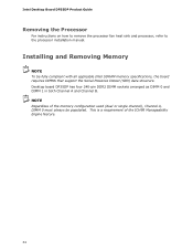
... Presence Detect (SPD) data structure. Installing and Removing Memory NOTE To be populated. Desktop board DP35DP has four 240-pin DDR2 DIMM sockets arranged as DIMM 0 and DIMM 1 in both Channel A and Channel B. Intel Desktop Board DP35DP Product Guide Removing the Processor For instructions on how to remove the processor fan heat sink and processor, refer to the processor installation manual.
... Presence Detect (SPD) data structure. Installing and Removing Memory NOTE To be populated. Desktop board DP35DP has four 240-pin DDR2 DIMM sockets arranged as DIMM 0 and DIMM 1 in both Channel A and Channel B. Intel Desktop Board DP35DP Product Guide Removing the Processor For instructions on how to remove the processor fan heat sink and processor, refer to the processor installation manual.

Product Guide
Page 53
... 2 x 12 pin connector. 3. Connect the main power supply cable to the board or the system may not function properly. Connect the 12 V processor core voltage power supply cable to the 2 x 2 pin connector. 53 Figure 26 shows the location of the Desktop Board power connectors. Figure 26. The 2 x 12 pin main power connector on page...
... 2 x 12 pin connector. 3. Connect the main power supply cable to the board or the system may not function properly. Connect the 12 V processor core voltage power supply cable to the 2 x 2 pin connector. 53 Figure 26 shows the location of the Desktop Board power connectors. Figure 26. The 2 x 12 pin main power connector on page...
Product Guide
Page 71
...The firmware has detected that a Single-Bit ECC Error occurred. Beep Codes Beep 3 Siren Description No memory Processor overheat (on the monitor BIOS Beep Codes The BIOS also issues a beep code (one long tone followed...SINGLE_BIT_ECC_ERROR CMOS_BATTERY_ERROR CMOS_CHECKSUM_ERROR CMOS_TIMER_ERROR MEMORY_SIZE_DECREASE_ERROR INTRUDER_DETECTION_ERROR SPD_TOLER_ERROR MEM_OPTIMAL_ERROR Explanation Processor was opened. The firmware has detected that a Multi-Bit ECC Error occurred. A Error Messages and Indicators Desktop Board DP35DP reports POST errors in each channel. 71 The ...
...The firmware has detected that a Single-Bit ECC Error occurred. Beep Codes Beep 3 Siren Description No memory Processor overheat (on the monitor BIOS Beep Codes The BIOS also issues a beep code (one long tone followed...SINGLE_BIT_ECC_ERROR CMOS_BATTERY_ERROR CMOS_CHECKSUM_ERROR CMOS_TIMER_ERROR MEMORY_SIZE_DECREASE_ERROR INTRUDER_DETECTION_ERROR SPD_TOLER_ERROR MEM_OPTIMAL_ERROR Explanation Processor was opened. The firmware has detected that a Multi-Bit ECC Error occurred. A Error Messages and Indicators Desktop Board DP35DP reports POST errors in each channel. 71 The ...


