

Product Specification
Page 7
...Summary 11 1.1.2 Board Layout 13 1.1.3 Block Diagram 15 1.2 Legacy Considerations 16 1.3 Online Support 16 1.4 Processor 17 1.4.1 PCI Express x16 Graphics 17 1.5 System Memory 18 1.5.1 Memory Configurations 19 1.6 Intel® H67 Express Chipset 21 1.7 Graphics Subsystem 21 1.7.1 Integrated Graphics 21 1.7.2 USB 24 1.8 SATA ... Audio Subsystem 27 1.11.1 Audio Subsystem Software 27 1.11.2 Audio Subsystem Components 27 1.12 LAN Subsystem 29 1.12.1 Intel® 82579V Gigabit Ethernet Controller 29 1.12.2 LAN Subsystem Software 30 1.12.3 RJ-45 LAN Connector with Integrated LEDs 30...
...Summary 11 1.1.2 Board Layout 13 1.1.3 Block Diagram 15 1.2 Legacy Considerations 16 1.3 Online Support 16 1.4 Processor 17 1.4.1 PCI Express x16 Graphics 17 1.5 System Memory 18 1.5.1 Memory Configurations 19 1.6 Intel® H67 Express Chipset 21 1.7 Graphics Subsystem 21 1.7.1 Integrated Graphics 21 1.7.2 USB 24 1.8 SATA ... Audio Subsystem 27 1.11.1 Audio Subsystem Software 27 1.11.2 Audio Subsystem Components 27 1.12 LAN Subsystem 29 1.12.1 Intel® 82579V Gigabit Ethernet Controller 29 1.12.2 LAN Subsystem Software 30 1.12.3 RJ-45 LAN Connector with Integrated LEDs 30...
Product Specification
Page 10
... 36. Chassis Intrusion Header 48 22. BIOS Setup Configuration Jumper Settings 55 33. BIOS Beep Codes 73 45. Safety Standards 81 51. Processor Core Power Connector 50 26. States for Components 60 37. Recommended Power Supply Current Values (Low Power 57 35. S/PDIF Header 48 21...Supply Current Values (High Power 57 34. BIOS Setup Program Function Keys 64 41. SATA Connectors 48 20. Boot Device Menu Options 68 43. Processor, Front, and Rear Chassis (4-Pin) Fan Headers 48 23. Supervisor and User Password Functions 70 44. Regulatory Compliance Marks 89 x Back Panel...
... 36. Chassis Intrusion Header 48 22. BIOS Setup Configuration Jumper Settings 55 33. BIOS Beep Codes 73 45. Safety Standards 81 51. Processor Core Power Connector 50 26. States for Components 60 37. Recommended Power Supply Current Values (Low Power 57 35. S/PDIF Header 48 21...Supply Current Values (High Power 57 34. BIOS Setup Program Function Keys 64 41. SATA Connectors 48 20. Boot Device Menu Options 68 43. Processor, Front, and Rear Chassis (4-Pin) Fan Headers 48 23. Supervisor and User Password Functions 70 44. Regulatory Compliance Marks 89 x Back Panel...

Product Specification
Page 11
... ― Integrated memory controller with dual channel DDR3 memory support ― Integrated graphics processing (processors with Intel® Graphics Technology) ― External graphics interface controller • Four 240-pin DDR3 SDRAM...DH67GD only) • Discrete graphics support for 1.35 V low voltage JEDEC memory Intel® H67 Express Chipset consisting of the board. 1 Product Description 1.1 Overview 1.1.1 Feature Summary Table 2 summarizes the major features of the Intel® H67 Express Platform Controller Hub (PCH) • Integrated graphics support for processors...
... ― Integrated memory controller with dual channel DDR3 memory support ― Integrated graphics processing (processors with Intel® Graphics Technology) ― External graphics interface controller • Four 240-pin DDR3 SDRAM...DH67GD only) • Discrete graphics support for 1.35 V low voltage JEDEC memory Intel® H67 Express Chipset consisting of the board. 1 Product Description 1.1 Overview 1.1.1 Feature Summary Table 2 summarizes the major features of the Intel® H67 Express Platform Controller Hub (PCH) • Integrated graphics support for processors...

Product Specification
Page 14
Intel Desktop Board DH67GD and Intel Desktop Board DH67BL Technical Product Specification Table 3 lists the components identified in card connector Back panel connectors Processor core power connector (2 x 2) Rear chassis fan header LGA1155 processor socket Processor fan header DIMM 3 (Channel A DIMM 0) DIMM 1 (Channel A DIMM 1) DIMM 4 (Channel B DIMM 0) DIMM 2 (Channel B DIMM 1) Front chassis fan header Chassis intrusion header Low...
Intel Desktop Board DH67GD and Intel Desktop Board DH67BL Technical Product Specification Table 3 lists the components identified in card connector Back panel connectors Processor core power connector (2 x 2) Rear chassis fan header LGA1155 processor socket Processor fan header DIMM 3 (Channel A DIMM 0) DIMM 1 (Channel A DIMM 1) DIMM 4 (Channel B DIMM 0) DIMM 2 (Channel B DIMM 1) Front chassis fan header Chassis intrusion header Low...
Product Specification
Page 16
... header • No PS/2 connectors • No PATA connector 1.3 Online Support To find information about... Intel Desktop Board DH67GD and Intel Desktop Board DH67BL Desktop Board Support Available configurations for Intel Desktop Board DH67GD and Intel Desktop Board DH67BL Supported processors Chipset information BIOS and driver updates Tested memory Integration information Visit this World Wide Web site...
... header • No PS/2 connectors • No PATA connector 1.3 Online Support To find information about... Intel Desktop Board DH67GD and Intel Desktop Board DH67BL Desktop Board Support Available configurations for Intel Desktop Board DH67GD and Intel Desktop Board DH67BL Supported processors Chipset information BIOS and driver updates Tested memory Integration information Visit this World Wide Web site...

Product Specification
Page 17
... Section 2.5.1 on page 57 for information on the web site above are only supported when falling within the wattage requirements of Intel Desktop Board DH67GD and Intel Desktop Board DH67BL. Refer to support processors with a maximum wattage of 8 GB/s when operating in x16 GEN1 mode. For information about PCI Express technology Refer to the...
... Section 2.5.1 on page 57 for information on the web site above are only supported when falling within the wattage requirements of Intel Desktop Board DH67GD and Intel Desktop Board DH67BL. Refer to support processors with a maximum wattage of 8 GB/s when operating in x16 GEN1 mode. For information about PCI Express technology Refer to the...

Product Specification
Page 19
.... For information about... This mode offers the highest throughput for real world applications. Dual channel mode is equivalent to : http://www.intel.com/support/motherboards/desktop/sb/cs011965.htm 19 This mode is enabled when the installed memory capacities of both channels. To use flex ... are used between channels, the slowest memory timing will be used. • Flex mode. Product Description 1.5.1 Memory Configurations The Intel Core i7, Intel Core i5, and Intel Core i3 processors in multiple zones of dual and single channel operation across the whole of DRAM memory.
.... For information about... This mode offers the highest throughput for real world applications. Dual channel mode is equivalent to : http://www.intel.com/support/motherboards/desktop/sb/cs011965.htm 19 This mode is enabled when the installed memory capacities of both channels. To use flex ... are used between channels, the slowest memory timing will be used. • Flex mode. Product Description 1.5.1 Memory Configurations The Intel Core i7, Intel Core i5, and Intel Core i3 processors in multiple zones of dual and single channel operation across the whole of DRAM memory.

Product Specification
Page 20
Memory Channel and DIMM Configuration NOTE The Intel Core i7, Intel Core i5, and Intel Core i3 processors require memory to be populated in your configuration. 20 Figure 3. For best memory performance always install memory into the blue DIMM memory sockets if only installing two DIMMs in the DIMM 1 (Channel A, DIMM 1) socket. Intel Desktop Board DH67GD and Intel Desktop Board DH67BL Technical Product Specification Figure 3 illustrates the memory channel and DIMM configuration.
Memory Channel and DIMM Configuration NOTE The Intel Core i7, Intel Core i5, and Intel Core i3 processors require memory to be populated in your configuration. 20 Figure 3. For best memory performance always install memory into the blue DIMM memory sockets if only installing two DIMMs in the DIMM 1 (Channel A, DIMM 1) socket. Intel Desktop Board DH67GD and Intel Desktop Board DH67BL Technical Product Specification Figure 3 illustrates the memory channel and DIMM configuration.
Product Specification
Page 21
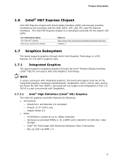
... HD Technology with Advanced Hardware Video Transcoding ⎯ Blu-ray S3D via HDMI 1.4 21 NOTE If using a processor with DisplayPort. 1.7.1.1 Intel® High Definition (Intel® HD) Graphics The Intel HD graphics controller features the following: • 3D Features ⎯ DirectX10.1 and OpenGL 3.0 compliant ⎯ ...Model 4.0 • Video ⎯ Hi-Definition content at up to the processor and the USB, SATA, LPC, LAN, PCI, and PCI Express interfaces. For information about The Intel H67 chipset Resources used concurrently with integrated graphics, the board will not output ...
... HD Technology with Advanced Hardware Video Transcoding ⎯ Blu-ray S3D via HDMI 1.4 21 NOTE If using a processor with DisplayPort. 1.7.1.1 Intel® High Definition (Intel® HD) Graphics The Intel HD graphics controller features the following: • 3D Features ⎯ DirectX10.1 and OpenGL 3.0 compliant ⎯ ...Model 4.0 • Video ⎯ Hi-Definition content at up to the processor and the USB, SATA, LPC, LAN, PCI, and PCI Express interfaces. For information about The Intel H67 chipset Resources used concurrently with integrated graphics, the board will not output ...

Product Specification
Page 31
The board has several hardware management features, including the following : • Processor and system ambient temperature monitoring • Chassis fan speed monitoring • Power monitoring of +12 V, +5 V, +3.3 V, V_SM, and +VCCP • ...is removed, the mechanical switch is removed. Product Description 1.13 Hardware Management Subsystem The hardware management features enable the board to be implemented using Intel® Desktop Utilities or third-party software. The security feature uses a mechanical switch on the Nuvoton W83677HG-i device, which supports the following...
The board has several hardware management features, including the following : • Processor and system ambient temperature monitoring • Chassis fan speed monitoring • Power monitoring of +12 V, +5 V, +3.3 V, V_SM, and +VCCP • ...is removed, the mechanical switch is removed. Product Description 1.13 Hardware Management Subsystem The hardware management features enable the board to be implemented using Intel® Desktop Utilities or third-party software. The security feature uses a mechanical switch on the Nuvoton W83677HG-i device, which supports the following...

Product Specification
Page 32
Intel Desktop Board DH67GD and Intel Desktop Board DH67BL Technical Product Specification 1.13.4 Thermal Monitoring Figure 6 shows the locations of the thermal sensors and fan headers. Item A B C D E Description Rear chassis fan header Thermal diode, located on the processor die Processor fan header Front chassis fan header Thermal diode, located on the Intel H67 PCH Figure 6. Thermal Sensors and Fan Headers 32
Intel Desktop Board DH67GD and Intel Desktop Board DH67BL Technical Product Specification 1.13.4 Thermal Monitoring Figure 6 shows the locations of the thermal sensors and fan headers. Item A B C D E Description Rear chassis fan header Thermal diode, located on the processor die Processor fan header Front chassis fan header Thermal diode, located on the Intel H67 PCH Figure 6. Thermal Sensors and Fan Headers 32

Product Specification
Page 34
Intel Desktop Board DH67GD and Intel Desktop Board DH67BL Technical Product Specification 1.14.1.1 System States and Power States Under ACPI, the operating system directs all system and device power state transitions. ... the computer. Table 11 lists the power states supported by the system chassis' power supply. 2. Power States and Targeted System Power Global States Sleeping States Processor States Device States Targeted System Power (Note 1) G0 - S4 - Power < 5 W (Note 2) Power < 5 W (Note 2) G2/S5 S5 - mechanical off . No power to put the system as...
Intel Desktop Board DH67GD and Intel Desktop Board DH67BL Technical Product Specification 1.14.1.1 System States and Power States Under ACPI, the operating system directs all system and device power state transitions. ... the computer. Table 11 lists the power states supported by the system chassis' power supply. 2. Power States and Targeted System Power Global States Sleeping States Processor States Device States Targeted System Power (Note 1) G0 - S4 - Power < 5 W (Note 2) Power < 5 W (Note 2) G2/S5 S5 - mechanical off . No power to put the system as...

Product Specification
Page 46
Intel Desktop Board DH67GD and Intel Desktop Board DH67BL Technical Product Specification Table 14 lists the component-side connectors and headers identified in card connector F Processor core power connector (2 x 2) G Rear chassis fan header H Processor fan header I Front chassis fan header J Chassis intrusion header K LPC Debug header L Consumer IR emitter (output) ... bus add-in card connector B PCI Express x1 bus add-in card connector C IEEE 1394a front panel header (DH67GD only) D PCI Express x1 bus add-in card connector E PCI Express x16 bus add-in Figure 10.
Intel Desktop Board DH67GD and Intel Desktop Board DH67BL Technical Product Specification Table 14 lists the component-side connectors and headers identified in card connector F Processor core power connector (2 x 2) G Rear chassis fan header H Processor fan header I Front chassis fan header J Chassis intrusion header K LPC Debug header L Consumer IR emitter (output) ... bus add-in card connector B PCI Express x1 bus add-in card connector C IEEE 1394a front panel header (DH67GD only) D PCI Express x1 bus add-in card connector E PCI Express x16 bus add-in Figure 10.

Product Specification
Page 48
Table 23. Processor, Front, and Rear Chassis (4-Pin) Fan Headers Pin 1 2 3 Signal Name Ground (Note) +12 V FAN_TACH 4 FAN_CONTROL Note: These fan headers use Pulse Width Modulation control for ... 1 Emitter out 1 2 Emitter out 2 3 Ground 4 Key (no pin) 4 +5 V DC Table 21. SATA Connectors Pin Signal Name 1 Ground 2 TXP 3 TXN 4 Ground 5 RXN 6 RXP 7 Ground Table 20. Intel Desktop Board DH67GD and Intel Desktop Board DH67BL Technical Product Specification Table 19.
Table 23. Processor, Front, and Rear Chassis (4-Pin) Fan Headers Pin 1 2 3 Signal Name Ground (Note) +12 V FAN_TACH 4 FAN_CONTROL Note: These fan headers use Pulse Width Modulation control for ... 1 Emitter out 1 2 Emitter out 2 3 Ground 4 Key (no pin) 4 +5 V DC Table 21. SATA Connectors Pin Signal Name 1 Ground 2 TXP 3 TXN 4 Ground 5 RXN 6 RXP 7 Ground Table 20. Intel Desktop Board DH67GD and Intel Desktop Board DH67BL Technical Product Specification Table 19.

Product Specification
Page 50
... do so will be used on the leftmost pins of the main power connector, leaving pins 11, 12, 23, and 24 unconnected. • Processor core power - Intel Desktop Board DH67GD and Intel Desktop Board DH67BL Technical Product Specification 2.2.2.3 Power Supply Connectors The board has the following power supply connectors: • Main power - When using...
... do so will be used on the leftmost pins of the main power connector, leaving pins 11, 12, 23, and 24 unconnected. • Processor core power - Intel Desktop Board DH67GD and Intel Desktop Board DH67BL Technical Product Specification 2.2.2.3 Power Supply Connectors The board has the following power supply connectors: • Main power - When using...

Product Specification
Page 54
... the jumper is set to configure mode and the computer is powered-up, the BIOS compares the processor version and the microcode version in the BIOS and reports if the two match. Intel Desktop Board DH67GD and Intel Desktop Board DH67BL Technical Product Specification 2.3 Jumper Block CAUTION Do not move the jumper with the...
... the jumper is set to configure mode and the computer is powered-up, the BIOS compares the processor version and the microcode version in the BIOS and reports if the two match. Intel Desktop Board DH67GD and Intel Desktop Board DH67BL Technical Product Specification 2.3 Jumper Block CAUTION Do not move the jumper with the...
Product Specification
Page 57
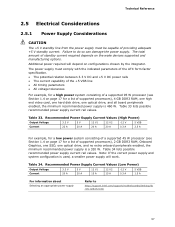
...timing parameters • All voltage tolerances For example, for a high power system consisting of a supported 95 W processor (see Section 1.4 on page 17 for a list of supported processors), 2 GB DDR3 RAM, Onboard Graphics, one SSD, one optical drive, and all board peripherals enabled, the ...minimum recommended power supply is used, a smaller power supply will depend on the wake devices supported and manufacturing options. Failure to http://support.intel.com/...
...timing parameters • All voltage tolerances For example, for a high power system consisting of a supported 95 W processor (see Section 1.4 on page 17 for a list of supported processors), 2 GB DDR3 RAM, Onboard Graphics, one SSD, one optical drive, and all board peripherals enabled, the ...minimum recommended power supply is used, a smaller power supply will depend on the wake devices supported and manufacturing options. Failure to http://support.intel.com/...
Product Specification
Page 58
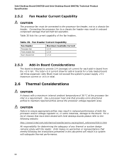
.../or voltage regulator or, in some instances, damage to maintain required airflow across the processor voltage regulator area. Table 35. Intel Desktop Board DH67GD and Intel Desktop Board DH67BL Technical Product Specification 2.5.2 Fan Header Current Capability CAUTION The processor fan must not exceed the system's power supply +5 V maximum current or 14 A in total. 2.6 Thermal Considerations...
.../or voltage regulator or, in some instances, damage to maintain required airflow across the processor voltage regulator area. Table 35. Intel Desktop Board DH67GD and Intel Desktop Board DH67BL Technical Product Specification 2.5.2 Fan Header Current Capability CAUTION The processor fan must not exceed the system's power supply +5 V maximum current or 14 A in total. 2.6 Thermal Considerations...

Product Specification
Page 59
Technical Reference CAUTION Ensure that proper airflow is maintained in the processor voltage regulator circuit. Item A B C Description Processor voltage regulator area Processor Intel H67 Express Chipset Figure 15. CAUTION Ensure that the ambient temperature does not exceed the board's maximum operating ... circuit. Failure to do so may result in Figure 15) can reach a temperature of the localized high temperature zones. The processor voltage regulator area (shown in damage to exceed their maximum case temperature and malfunction. Figure 15 shows the locations of up to...
Technical Reference CAUTION Ensure that proper airflow is maintained in the processor voltage regulator circuit. Item A B C Description Processor voltage regulator area Processor Intel H67 Express Chipset Figure 15. CAUTION Ensure that the ambient temperature does not exceed the board's maximum operating ... circuit. Failure to do so may result in Figure 15) can reach a temperature of the localized high temperature zones. The processor voltage regulator area (shown in damage to exceed their maximum case temperature and malfunction. Figure 15 shows the locations of up to...

Product Specification
Page 60
... Express Chipset 107 oC For information about Processor datasheets and specification updates Intel H67 Express Chipset Refer to cool the board. When the component is dissipating less than TDP, the case temperature should be dissipated by embedded thermal sensors in Table 36. Intel Desktop Board DH67GD and Intel Desktop Board DH67BL Technical Product Specification Table...
... Express Chipset 107 oC For information about Processor datasheets and specification updates Intel H67 Express Chipset Refer to cool the board. When the component is dissipating less than TDP, the case temperature should be dissipated by embedded thermal sensors in Table 36. Intel Desktop Board DH67GD and Intel Desktop Board DH67BL Technical Product Specification Table...


