
Product Guide
Page 6
...*, e-Standby, and ErP Compliance 77 vi Intel Desktop Board DH61WW Product Guide Connecting to the Internal Headers 43 Front Panel Audio Header 44 S/PDIF Header 44 Chassis Intrusion Header 45 TPM Header 45 Front Panel Header 46 Serial Header 46 Front Panel USB 2.0 Header 47 Connecting to the Audio System 48 Connecting Chassis Fan and Power Supply Cables...
...*, e-Standby, and ErP Compliance 77 vi Intel Desktop Board DH61WW Product Guide Connecting to the Internal Headers 43 Front Panel Audio Header 44 S/PDIF Header 44 Chassis Intrusion Header 45 TPM Header 45 Front Panel Header 46 Serial Header 46 Front Panel USB 2.0 Header 47 Connecting to the Audio System 48 Connecting Chassis Fan and Power Supply Cables...

Product Guide
Page 7
Intel Desktop Board DH61WW Components 12 2. Intel Desktop Board DH61WW Mounting Screw Hole Locations 30 6. Use DDR3 DIMMs 37 14. Removing a PCI Express x16 Graphics Card 41 17. Removing the Battery 58 24. Contents Figures 1. Unlatch the Socket Lever 31 7. Install the Processor 33 10. Dual Channel Memory Configuration Example 36 13. Connecting...the Chassis Fan Header 49 21. Intel Desktop Board DH61WW China RoHS Material Self Declaration Table 72 vii Connecting Power Supply Cables 50 22. ...Connecting the Processor Fan Heat Sink Power Cable to the Processor Fan Header ...
Intel Desktop Board DH61WW Components 12 2. Intel Desktop Board DH61WW Mounting Screw Hole Locations 30 6. Use DDR3 DIMMs 37 14. Removing a PCI Express x16 Graphics Card 41 17. Removing the Battery 58 24. Contents Figures 1. Unlatch the Socket Lever 31 7. Install the Processor 33 10. Dual Channel Memory Configuration Example 36 13. Connecting...the Chassis Fan Header 49 21. Intel Desktop Board DH61WW China RoHS Material Self Declaration Table 72 vii Connecting Power Supply Cables 50 22. ...Connecting the Processor Fan Heat Sink Power Cable to the Processor Fan Header ...

Product Guide
Page 16
...supports analog displays. The maximum theoretical bandwidth on the interface is connected to an audio port. Audio Subsystem The board supports Intel High Definition Audio through the Intel® Flexible Display Interface (Intel® FDI) for processors with independent multi-streaming stereo •...PCI Express* x16 Graphics Intel Core i7, Intel Core i5, Intel Core i3, and Intel Pentium processors in an LGA1155 package support discrete add-in graphics cards via back panel connectors • Headphone and Mic in x16 mode. Intel Desktop Board DH61WW Product Guide Graphics Subsystem The...
...supports analog displays. The maximum theoretical bandwidth on the interface is connected to an audio port. Audio Subsystem The board supports Intel High Definition Audio through the Intel® Flexible Display Interface (Intel® FDI) for processors with independent multi-streaming stereo •...PCI Express* x16 Graphics Intel Core i7, Intel Core i5, Intel Core i3, and Intel Pentium processors in an LGA1155 package support discrete add-in graphics cards via back panel connectors • Headphone and Mic in x16 mode. Intel Desktop Board DH61WW Product Guide Graphics Subsystem The...
Product Guide
Page 17
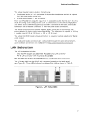
... indicate the status of 8 Ω at 1 W (rms) or 4 Ω at http://downloadcenter.intel.com/. LAN Status LEDs 17 The onboard S/PDIF header allows connection to coaxial or optical adapters for front panel audio connectors) • S/PDIF audio header (1 x 4 pin header) Front panel headphone output is capable of driving a speaker load of the LAN as...
... indicate the status of 8 Ω at 1 W (rms) or 4 Ω at http://downloadcenter.intel.com/. LAN Status LEDs 17 The onboard S/PDIF header allows connection to coaxial or optical adapters for front panel audio connectors) • S/PDIF audio header (1 x 4 pin header) Front panel headphone output is capable of driving a speaker load of the LAN as...
Product Guide
Page 27
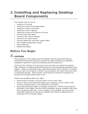
...processor • Install and remove memory • Install and remove a PCI Express x16 card • Connect Serial ATA cables • Connect to the internal headers • Connect to the audio system • Connect chassis fan and power supply cables • Set the BIOS configuration jumper • Clear passwords •...at an ESD workstation using and modifying electronic equipment. Some circuitry on the board can continue to operate even though the front panel power button is not available, you can provide some ESD protection by wearing an antistatic wrist strap and attaching it to a...
...processor • Install and remove memory • Install and remove a PCI Express x16 card • Connect Serial ATA cables • Connect to the internal headers • Connect to the audio system • Connect chassis fan and power supply cables • Set the BIOS configuration jumper • Clear passwords •...at an ESD workstation using and modifying electronic equipment. Some circuitry on the board can continue to operate even though the front panel power button is not available, you can provide some ESD protection by wearing an antistatic wrist strap and attaching it to a...

Product Guide
Page 40
Intel Desktop Board DH61WW Product Guide Follow these instructions to the chassis back panel with a screw (Figure 15, B). 4. Figure 15. Secure the card's metal bracket to install a PCI Express x16 graphics card: 1. Observe the precautions in the connector and... the card retention notch on the card snaps into place around the retention mechanism pin on page 27. 2. Connect a monitor to ...
Intel Desktop Board DH61WW Product Guide Follow these instructions to the chassis back panel with a screw (Figure 15, B). 4. Figure 15. Secure the card's metal bracket to install a PCI Express x16 graphics card: 1. Observe the precautions in the connector and... the card retention notch on the card snaps into place around the retention mechanism pin on page 27. 2. Connect a monitor to ...

Product Guide
Page 44
... DH61WW Product Guide Front Panel Audio Header The front panel audio header shown in Figure 18, A supports both Intel High Definition Audio and AC '97 Audio. Table 4. Table 6. Table 4 shows the pin assignments and signal names for HD Audio and Table 5 shows the pin assignments and signal names for the S/PDIF output header. Front Panel...
... DH61WW Product Guide Front Panel Audio Header The front panel audio header shown in Figure 18, A supports both Intel High Definition Audio and AC '97 Audio. Table 4. Table 6. Table 4 shows the pin assignments and signal names for HD Audio and Table 5 shows the pin assignments and signal names for the S/PDIF output header. Front Panel...

Product Guide
Page 46
... Out In NOTE When connecting individual wires from your chassis front panel to the front panel header, be sure to +5 V Out 2 Front panel LED+ 3 Hard disk active LED Out 4 Front panel LED- Table 10. Table 10 shows the pin assignments and signal names for the front panel header. Intel Desktop Board DH61WW Product Guide Front Panel Header Figure 18...
... Out In NOTE When connecting individual wires from your chassis front panel to the front panel header, be sure to +5 V Out 2 Front panel LED+ 3 Hard disk active LED Out 4 Front panel LED- Table 10. Table 10 shows the pin assignments and signal names for the front panel header. Intel Desktop Board DH61WW Product Guide Front Panel Header Figure 18...

Product Guide
Page 47
... 2.0 Header Figure 18, G shows the location of the front panel USB 2.0 header and Table 11 shows the pin assignments and signal names. Table 11. Use a shielded cable that have an unshielded cable attached to a USB ... not meet FCC Class B requirements, even if no device or a low-speed USB device is attached to the cable. Front Panel USB 2.0 Header Signal Names Pin Signal Name 1 Power (+5 V) 3 D- 5 D+ 7 Ground 9 Key Pin Signal Name 2 Power (+5 V) 4 D- 6 D+ 8 Ground 10 No Connection NOTE Computer systems that meets the requirements for a full-speed USB device. 47
... 2.0 Header Figure 18, G shows the location of the front panel USB 2.0 header and Table 11 shows the pin assignments and signal names. Table 11. Use a shielded cable that have an unshielded cable attached to a USB ... not meet FCC Class B requirements, even if no device or a low-speed USB device is attached to the cable. Front Panel USB 2.0 Header Signal Names Pin Signal Name 1 Power (+5 V) 3 D- 5 D+ 7 Ground 9 Key Pin Signal Name 2 Power (+5 V) 4 D- 6 D+ 8 Ground 10 No Connection NOTE Computer systems that meets the requirements for a full-speed USB device. 47

Product Guide
Page 48
... table. Poor audio quality may occur if passive (non-amplified) speakers are shown in Figure 19. Intel Desktop Board DH61WW Product Guide Connecting to power either headphones or amplified speakers only. Back Panel Audio Connectors NOTE The back panel line out connector is designed to the Audio System After installing the Realtek audio driver from...
... table. Poor audio quality may occur if passive (non-amplified) speakers are shown in Figure 19. Intel Desktop Board DH61WW Product Guide Connecting to power either headphones or amplified speakers only. Back Panel Audio Connectors NOTE The back panel line out connector is designed to the Audio System After installing the Realtek audio driver from...

DH61WW Technical Product Specification
Page 9
...Memory Address Map 39 9. Connection Diagram for Intel HD Audio 45 15. Feature Summary 11 2. Audio Jack Support 23 5. Component-side Connectors and Headers Shown in Figure 1 14 3. Front Panel Audio Header for Front Panel Header 48 12. Front Panel Audio Header for Front Panel USB Headers 50 13. ... Zones 57 Tables 1. Effects of the Standby Power LED (Green 37 8. Serial Port Header 44 13. Front Panel USB Header 45 17. Block Diagram 15 3. Connection Diagram for AC '97 Audio 45 16. LAN Connector LED States 27 6. TPM Header 44 12. Location of...
...Memory Address Map 39 9. Connection Diagram for Intel HD Audio 45 15. Feature Summary 11 2. Audio Jack Support 23 5. Component-side Connectors and Headers Shown in Figure 1 14 3. Front Panel Audio Header for Front Panel Header 48 12. Front Panel Audio Header for Front Panel USB Headers 50 13. ... Zones 57 Tables 1. Effects of the Standby Power LED (Green 37 8. Serial Port Header 44 13. Front Panel USB Header 45 17. Block Diagram 15 3. Connection Diagram for AC '97 Audio 45 16. LAN Connector LED States 27 6. TPM Header 44 12. Location of...

DH61WW Technical Product Specification
Page 23
Product Description 1.11 Audio Subsystem The board supports Intel High Definition Audio through back panel jacks • Headphone and Mic in functions for the back panel audio jacks that enables the audio codec to recognize the device that is connected to the user's definition, or can be automatically switched depending on the recognized device type...
Product Description 1.11 Audio Subsystem The board supports Intel High Definition Audio through back panel jacks • Headphone and Mic in functions for the back panel audio jacks that enables the audio codec to recognize the device that is connected to the user's definition, or can be automatically switched depending on the recognized device type...
DH61WW Technical Product Specification
Page 25
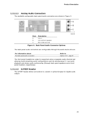
... audio output. 25 Product Description 1.11.2.1 Analog Audio Connectors The available configurable back panel audio connectors are configurable through back panel speakers and a front panel headset, respectively). 1.11.2.2 S/PDIF Header The S/PDIF header allows connections to Section 2.2.1, page 41 The front panel headphone output is supported using a separate audio channel pair allowing multi-streaming audio...
... audio output. 25 Product Description 1.11.2.1 Analog Audio Connectors The available configurable back panel audio connectors are configurable through back panel speakers and a front panel headset, respectively). 1.11.2.2 S/PDIF Header The S/PDIF header allows connections to Section 2.2.1, page 41 The front panel headphone output is supported using a separate audio channel pair allowing multi-streaming audio...

DH61WW Technical Product Specification
Page 40
...the computer, the power cable, and the external devices themselves. Intel Desktop Board DH61WW Technical Product Specification 2.1.2 Memory Map Table 9 lists the system memory map. Do not use these groups: • Back panel I/O connectors • Component-side I/O connectors and headers (see...peripherals. The other internal connectors and headers are not overcurrent protected and should connect only to the PCI bus). EFFFF 800 K - 896 K C8000 - Table 9. Furthermore, improper connection of USB header single wire connectors may eventually overload the overcurrent protection and cause...
...the computer, the power cable, and the external devices themselves. Intel Desktop Board DH61WW Technical Product Specification 2.1.2 Memory Map Table 9 lists the system memory map. Do not use these groups: • Back panel I/O connectors • Component-side I/O connectors and headers (see...peripherals. The other internal connectors and headers are not overcurrent protected and should connect only to the PCI bus). EFFFF 800 K - 896 K C8000 - Table 9. Furthermore, improper connection of USB header single wire connectors may eventually overload the overcurrent protection and cause...

DH61WW Technical Product Specification
Page 41
Technical Reference 2.2.1 Back Panel Connectors Figure 9 shows the location of the back panel connectors for the board. Item A B C D E F G H I Description PS/2 keyboard/mouse connector USB 2.0 ports VGA connector Parallel port LAN USB 2.0 ports Line in Line out/front speakers Mic in/side surround Figure 9. Back Panel Connectors NOTE The back panel audio line out connector is designed to this output. 41 Poor audio quality occurs if passive (non-amplified) speakers are connected to power headphones or amplified speakers only.
Technical Reference 2.2.1 Back Panel Connectors Figure 9 shows the location of the back panel connectors for the board. Item A B C D E F G H I Description PS/2 keyboard/mouse connector USB 2.0 ports VGA connector Parallel port LAN USB 2.0 ports Line in Line out/front speakers Mic in/side surround Figure 9. Back Panel Connectors NOTE The back panel audio line out connector is designed to this output. 41 Poor audio quality occurs if passive (non-amplified) speakers are connected to power headphones or amplified speakers only.

DH61WW Technical Product Specification
Page 45
...9 [Port 2] Left channel 10 [Port 2] SENSE_RETURN Table 15. specifically, pins 4, 6, 7, and 10 are supported; Front Panel Audio Header for Intel HD Audio Pin Signal Name Pin Signal Name 1 [Port 1] Left channel 2 Ground 3 [Port 1] Right channel 4 PRESENCE...# (Dongle present) 5 [Port 2] Right channel 6 [Port 1] SENSE_RETURN 7 SENSE_SEND (Jack detection) 8 Key (no pin) 10 Signal Name +5 VDC DD+ Ground No Connect Table 17. Table 16. Front Panel...
...9 [Port 2] Left channel 10 [Port 2] SENSE_RETURN Table 15. specifically, pins 4, 6, 7, and 10 are supported; Front Panel Audio Header for Intel HD Audio Pin Signal Name Pin Signal Name 1 [Port 1] Left channel 2 Ground 3 [Port 1] Right channel 4 PRESENCE...# (Dongle present) 5 [Port 2] Right channel 6 [Port 1] SENSE_RETURN 7 SENSE_SEND (Jack detection) 8 Key (no pin) 10 Signal Name +5 VDC DD+ Ground No Connect Table 17. Table 16. Front Panel...
DH61WW Technical Product Specification
Page 48
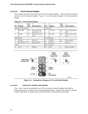
... Switch 6 PWR# 8 Ground Not Connected 10 N/C In/ Out Description Out Front panel green LED Out Front panel yellow LED In Power switch Ground Not connected Figure 11. Intel Desktop Board DH61WW Technical Product Specification 2.2.2.4 Front Panel Header This section describes the functions of the front panel header. Figure 11 is a connection diagram for Front Panel Header 2.2.2.4.1 Hard Drive Activity LED...
... Switch 6 PWR# 8 Ground Not Connected 10 N/C In/ Out Description Out Front panel green LED Out Front panel yellow LED In Power switch Ground Not connected Figure 11. Intel Desktop Board DH61WW Technical Product Specification 2.2.2.4 Front Panel Header This section describes the functions of the front panel header. Figure 11 is a connection diagram for Front Panel Header 2.2.2.4.1 Hard Drive Activity LED...

DH61WW Technical Product Specification
Page 49
Table 23. When the switch is closed, the board resets and runs the POST. 2.2.2.4.3 Power LED Header Pins 2 and 4 can be connected to a momentary single pole, single throw (SPST) type switch that is due to internal debounce circuitry on the board.) At least two seconds must pull ... switch must pass before the power supply will recognize another on/off /sleeping Steady Lit Running Blink Standby 2.2.2.4.4 Power Switch Header Pins 6 and 8 can be connected to a front panel momentary-contact power switch. Technical Reference 2.2.2.4.2 Reset Switch Header Pins 5 and 7 can be...
Table 23. When the switch is closed, the board resets and runs the POST. 2.2.2.4.3 Power LED Header Pins 2 and 4 can be connected to a momentary single pole, single throw (SPST) type switch that is due to internal debounce circuitry on the board.) At least two seconds must pull ... switch must pass before the power supply will recognize another on/off /sleeping Steady Lit Running Blink Standby 2.2.2.4.4 Power Switch Header Pins 6 and 8 can be connected to a front panel momentary-contact power switch. Technical Reference 2.2.2.4.2 Reset Switch Header Pins 5 and 7 can be...

DH61WW Technical Product Specification
Page 50
Intel Desktop Board DH61WW Technical Product Specification 2.2.2.5 Front Panel USB Headers Figure 12 is a connection diagram for Front Panel USB Headers 2.2.2.6 Low Pin Count (LPC) Debug Header During the POST, the BIOS generates diagnostic progress codes (... specification for determining the point where an error occurred (refer to I/O port 80h. Connection Diagram for the front panel USB headers. LPC Debug Header Pin Signal Name 1 CK_33M_DEBUG 3 PLTRST# 5 LAD0 7 LAD2 9 GND 11 +3.3 V 13 Not connected Pin Signal Name 2 GND 4 LFRAME# 6 LAD1 8 LAD3 10 GND 12 +3.3...
Intel Desktop Board DH61WW Technical Product Specification 2.2.2.5 Front Panel USB Headers Figure 12 is a connection diagram for Front Panel USB Headers 2.2.2.6 Low Pin Count (LPC) Debug Header During the POST, the BIOS generates diagnostic progress codes (... specification for determining the point where an error occurred (refer to I/O port 80h. Connection Diagram for the front panel USB headers. LPC Debug Header Pin Signal Name 1 CK_33M_DEBUG 3 PLTRST# 5 LAD0 7 LAD2 9 GND 11 +3.3 V 13 Not connected Pin Signal Name 2 GND 4 LFRAME# 6 LAD1 8 LAD3 10 GND 12 +3.3...


