

Product Guide
Page 5
Contents 1 Desktop Board Features Supported Operating Systems 11 Desktop Board Components 12 Processor ...14 Intel® H55 Express Chipset 14 Main Memory...15 Graphics Subsystem 15 Integrated Graphics 15 Analog Display (VGA 15 High-Definition Multimedia Interface* (HDMI 16 Digital Visual ... 17 USB 2.0 Support 18 Serial ATA Support 18 Expandability...18 Legacy I/O ...19 BIOS ...19 Serial ATA Auto Configuration 19 PCI*/PCI Express Auto Configuration 19 Security Passwords 19 Hardware Management 20 Hardware Monitoring and Fan Speed Control 20 Fan Monitoring 20 Power Management 21 ...
Contents 1 Desktop Board Features Supported Operating Systems 11 Desktop Board Components 12 Processor ...14 Intel® H55 Express Chipset 14 Main Memory...15 Graphics Subsystem 15 Integrated Graphics 15 Analog Display (VGA 15 High-Definition Multimedia Interface* (HDMI 16 Digital Visual ... 17 USB 2.0 Support 18 Serial ATA Support 18 Expandability...18 Legacy I/O ...19 BIOS ...19 Serial ATA Auto Configuration 19 PCI*/PCI Express Auto Configuration 19 Security Passwords 19 Hardware Management 20 Hardware Monitoring and Fan Speed Control 20 Fan Monitoring 20 Power Management 21 ...
Product Guide
Page 6
Intel Desktop Board DH55TC Product Guide 2 Installing and Replacing Desktop Board Components Before You Begin 27 Installation Precautions 28 Prevent Power Supply Overload 28 Observe Safety and Regulatory Requirements ... Dual Channel Memory Configuration 37 Two or Four DIMMs 37 Three DIMMs 38 Installing DIMMs 39 Removing DIMMs 41 Installing and Removing PCI Express x16 Graphics Cards 41 Installing a PCI Express x16 Graphics Card 41 Removing a PCI Express x16 Graphics Card 42 Connecting Serial ATA (SATA) Cables 44 Installing an Intel® Z-U130...
Intel Desktop Board DH55TC Product Guide 2 Installing and Replacing Desktop Board Components Before You Begin 27 Installation Precautions 28 Prevent Power Supply Overload 28 Observe Safety and Regulatory Requirements ... Dual Channel Memory Configuration 37 Two or Four DIMMs 37 Three DIMMs 38 Installing DIMMs 39 Removing DIMMs 41 Installing and Removing PCI Express x16 Graphics Cards 41 Installing a PCI Express x16 Graphics Card 41 Removing a PCI Express x16 Graphics Card 42 Connecting Serial ATA (SATA) Cables 44 Installing an Intel® Z-U130...
Product Guide
Page 7
... 8. Connecting the Processor Fan Heat Sink Power Cable to the Processor Fan Header 36 14. Example Dual Channel Memory Configuration with Two DIMMs 37 15. Installing an Intel Z-U130 USB Solid-State Drive (or Compatible Device 45 23. Location of the Standby Power Indicator 23 4. ... 61 29. Lower the Load Plate 35 12. Connecting Power Supply Cables 53 27. Intel Desktop Board DH55TC Mounting Screw Hole Locations 30 6. Remove the Socket Cover 33 9. Example Dual Channel Memory Configuration with Four DIMMs 38 16. Contents A Error Messages and Indicators BIOS Error Codes 67 ...
... 8. Connecting the Processor Fan Heat Sink Power Cable to the Processor Fan Header 36 14. Example Dual Channel Memory Configuration with Two DIMMs 37 15. Installing an Intel Z-U130 USB Solid-State Drive (or Compatible Device 45 23. Location of the Standby Power Indicator 23 4. ... 61 29. Lower the Load Plate 35 12. Connecting Power Supply Cables 53 27. Intel Desktop Board DH55TC Mounting Screw Hole Locations 30 6. Remove the Socket Cover 33 9. Example Dual Channel Memory Configuration with Four DIMMs 38 16. Contents A Error Messages and Indicators BIOS Error Codes 67 ...
Product Guide
Page 15
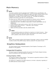
... the DIMM 0 (blue) memory sockets for the system to configure the memory controller for non-ECC, unbuffered, single-sided or double-sided DIMMs with x8 organization • 16 GB maximum total system memory (with 2 Gb memory technology) • Minimum total system memory: 1 GB using a processor without Intel Graphics Technology, memory must be populated with Intel Graphics Technology. Graphics Subsystem...
... the DIMM 0 (blue) memory sockets for the system to configure the memory controller for non-ECC, unbuffered, single-sided or double-sided DIMMs with x8 organization • 16 GB maximum total system memory (with 2 Gb memory technology) • Minimum total system memory: 1 GB using a processor without Intel Graphics Technology, memory must be populated with Intel Graphics Technology. Graphics Subsystem...

Product Guide
Page 27
...and remove the Desktop Board • Install and remove a processor • Install and remove memory • Install and remove a PCI Express x16 card • Connect Serial ATA cables • Install an Intel Z-U130 USB Solid-State Drive (or Compatible Device) • Connect to the internal headers and...the correct order. • Set up a log to record information about your computer, such as model, serial numbers, installed options, and configuration information. • Electrostatic discharge (ESD) can continue to a metal part of the procedures described in this chapter only at an ESD ...
...and remove the Desktop Board • Install and remove a processor • Install and remove memory • Install and remove a PCI Express x16 card • Connect Serial ATA cables • Install an Intel Z-U130 USB Solid-State Drive (or Compatible Device) • Connect to the internal headers and...the correct order. • Set up a log to record information about your computer, such as model, serial numbers, installed options, and configuration information. • Electrostatic discharge (ESD) can continue to a metal part of the procedures described in this chapter only at an ESD ...
Product Guide
Page 37
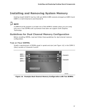
... or two DIMMs with Two DIMMs 37 Example Dual Channel Memory Configuration with a processor that does not support Intel Graphics Technology. NOTE A DIMM must be present in both Channel A and Channel B. Installing and Replacing Desktop Board Components Installing and Removing System Memory Desktop board DH55TC has four 240-pin DDR3 DIMM sockets arranged as DIMM...
... or two DIMMs with Two DIMMs 37 Example Dual Channel Memory Configuration with a processor that does not support Intel Graphics Technology. NOTE A DIMM must be present in both Channel A and Channel B. Installing and Replacing Desktop Board Components Installing and Removing System Memory Desktop board DH55TC has four 240-pin DDR3 DIMM sockets arranged as DIMM...

Product Guide
Page 38
... channel memory operation. 38 Intel Desktop Board DH55TC Product Guide If additional memory is to use three DIMMs in a dual-channel configuration, install a matched pair of DIMMs equal in speed and size in the DIMM 1 (black) sockets of channels A and B (see Figure 16). Figure 16. Example Dual Channel Memory Configuration with Three DIMMs NOTE All other memory configurations will...
... channel memory operation. 38 Intel Desktop Board DH55TC Product Guide If additional memory is to use three DIMMs in a dual-channel configuration, install a matched pair of DIMMs equal in speed and size in the DIMM 1 (black) sockets of channels A and B (see Figure 16). Figure 16. Example Dual Channel Memory Configuration with Three DIMMs NOTE All other memory configurations will...
Product Guide
Page 64
...writeable CD drive, and software capable of the BIOS by navigating to the Intel Desktop Board DH55TC page on the computer's hard drive and without the need to update the BIOS. Intel Desktop Board DH55TC Product Guide Updating the BIOS with the ISO Image BIOS Update File The ... to CD. The Iflash BIOS update file contains: • New BIOS file (including the Intel® Management Engine Firmware Image) • Intel® Integrator Toolkit Configuration File (optional) • Intel Flash Memory Update Utility You can be used to create a bootable CD that contains the files you need...
...writeable CD drive, and software capable of the BIOS by navigating to the Intel Desktop Board DH55TC page on the computer's hard drive and without the need to update the BIOS. Intel Desktop Board DH55TC Product Guide Updating the BIOS with the ISO Image BIOS Update File The ... to CD. The Iflash BIOS update file contains: • New BIOS file (including the Intel® Management Engine Firmware Image) • Intel® Integrator Toolkit Configuration File (optional) • Intel Flash Memory Update Utility You can be used to create a bootable CD that contains the files you need...
DH55TC Technical Product Specification
Page 5
Contents 1 Product Description 1.1 Overview 9 1.1.1 Feature Summary 9 1.1.2 Board Layout 11 1.1.3 Block Diagram 13 1.2 Legacy Considerations 14 1.3 Online Support 14 1.4 Processor 14 1.5 Intel® H55 Express Chipset 15 1.6 System Memory 15 1.6.1 Memory Configurations 16 1.7 Graphics Subsystem 18 1.7.1 Integrated Graphics 18 1.7.2 PCI Express x16 Graphics 19 1.8 USB 19 1.9 SATA Interfaces 20 1.10 Legacy I/O Controller 20 1.10.1 Serial Port...
Contents 1 Product Description 1.1 Overview 9 1.1.1 Feature Summary 9 1.1.2 Board Layout 11 1.1.3 Block Diagram 13 1.2 Legacy Considerations 14 1.3 Online Support 14 1.4 Processor 14 1.5 Intel® H55 Express Chipset 15 1.6 System Memory 15 1.6.1 Memory Configurations 16 1.7 Graphics Subsystem 18 1.7.1 Integrated Graphics 18 1.7.2 PCI Express x16 Graphics 19 1.8 USB 19 1.9 SATA Interfaces 20 1.10 Legacy I/O Controller 20 1.10.1 Serial Port...
DH55TC Technical Product Specification
Page 7
Memory Channel and DIMM Configuration 17 4. LAN Connector LED Locations 24 6. Location of the Jumper Block 49 15. Component-side Connectors and Headers 39 11. Connection Diagram for Front Panel USB Header (with Intel Z-U130 USB Solid-State Drive, or Compatible Device, Support 43 18. ...Devices and Events 29 8. Processor (4-Pin) Fan Header 43 20. Main Power Connector 45 23. Major Board Components 11 2. Supported Memory Configurations 15 4. System Memory Map 37 9. Front Panel USB Header 42 17. Block Diagram 13 3. Parallel Port Header 41 12. Front Panel Audio Header ...
Memory Channel and DIMM Configuration 17 4. LAN Connector LED Locations 24 6. Location of the Jumper Block 49 15. Component-side Connectors and Headers 39 11. Connection Diagram for Front Panel USB Header (with Intel Z-U130 USB Solid-State Drive, or Compatible Device, Support 43 18. ...Devices and Events 29 8. Processor (4-Pin) Fan Header 43 20. Main Power Connector 45 23. Major Board Components 11 2. Supported Memory Configurations 15 4. System Memory Map 37 9. Front Panel USB Header 42 17. Block Diagram 13 3. Parallel Port Header 41 12. Front Panel Audio Header ...
DH55TC Technical Product Specification
Page 9
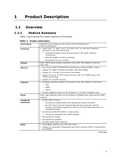
...with stacked back panel connectors ― Six front panel ports are implemented with Intel Graphics Technology: ― VGA ― HDMI ― DVI-D • Discrete graphics support for Advanced Configuration and Power Interface (ACPI), Plug and Play, and SMBIOS continued 9 one ...in an LGA1156 socket: ― Integrated graphics processing (processors with Intel® Graphics Technology) ― External graphics interface controller ― Integrated memory controller Intel® H55 Express Chipset consisting of the Intel® H55 Platform Controller Hub (PCH) • Four 240...
...with stacked back panel connectors ― Six front panel ports are implemented with Intel Graphics Technology: ― VGA ― HDMI ― DVI-D • Discrete graphics support for Advanced Configuration and Power Interface (ACPI), Plug and Play, and SMBIOS continued 9 one ...in an LGA1156 socket: ― Integrated graphics processing (processors with Intel® Graphics Technology) ― External graphics interface controller ― Integrated memory controller Intel® H55 Express Chipset consisting of the Intel® H55 Platform Controller Hub (PCH) • Four 240...
DH55TC Technical Product Specification
Page 14
... the power supply. Intel Desktop Board DH55TC Desktop Board Support Available configurations for the most up-to support the Intel Core i7, Intel Core i5, Intel Core i3, and Intel Pentium processors in the future. See the Intel web site listed below for the Intel Desktop Board DH55TC Supported processors Chipset information BIOS and driver updates Tested memory Integration information Visit...
... the power supply. Intel Desktop Board DH55TC Desktop Board Support Available configurations for the most up-to support the Intel Core i7, Intel Core i5, Intel Core i3, and Intel Pentium processors in the future. See the Intel web site listed below for the Intel Desktop Board DH55TC Supported processors Chipset information BIOS and driver updates Tested memory Integration information Visit...

DH55TC Technical Product Specification
Page 15
...the BIOS to read the SPD data and program the chipset to accurately configure memory settings for the board's I/O paths. Table 3 lists the supported DIMM configurations. Supported Memory Configurations DIMM Capacity Configuration (Note) SDRAM Density SDRAM Organization Front-side/Back-side Number of SDRAM...structure. Product Description 1.5 Intel® H55 Express Chipset The Intel H55 Express Chipset consisting of SDRAM). 15 Table 3. For information about The Intel H55 Express Chipset Resources used by the chipset Refer to correctly configure the memory settings, but performance ...
...the BIOS to read the SPD data and program the chipset to accurately configure memory settings for the board's I/O paths. Table 3 lists the supported DIMM configurations. Supported Memory Configurations DIMM Capacity Configuration (Note) SDRAM Density SDRAM Organization Front-side/Back-side Number of SDRAM...structure. Product Description 1.5 Intel® H55 Express Chipset The Intel H55 Express Chipset consisting of SDRAM). 15 Table 3. For information about The Intel H55 Express Chipset Resources used by the chipset Refer to correctly configure the memory settings, but performance ...
DH55TC Technical Product Specification
Page 16
...different speed DIMMs are equal. Memory Configuration Examples Refer to the other . Tested Memory Refer to: http://www.intel.com/support/motherboards/desktop/sb/CS025414.htm 1.6.1 Memory Configurations The Intel Core i7, Intel Core i5, Intel Core i3, and Intel Pentium processors support the following .... For information about ... Dual channel mode is installed or the memory capacities are used between channels, the slowest memory timing will be used. • Single channel (Asymmetric) mode. Intel Desktop Board DH55TC Technical Product Specification For information about ...
...different speed DIMMs are equal. Memory Configuration Examples Refer to the other . Tested Memory Refer to: http://www.intel.com/support/motherboards/desktop/sb/CS025414.htm 1.6.1 Memory Configurations The Intel Core i7, Intel Core i5, Intel Core i3, and Intel Pentium processors support the following .... For information about ... Dual channel mode is installed or the memory capacities are used between channels, the slowest memory timing will be used. • Single channel (Asymmetric) mode. Intel Desktop Board DH55TC Technical Product Specification For information about ...

DH55TC Technical Product Specification
Page 17
Figure 3. Memory Channel and DIMM Configuration NOTE When using a processor without Intel Graphics Technology: there must always be memory installed into any or both of the DIMM 0 (blue) memory slots for the system to boot. 17 Product Description Figure 3 illustrates the memory channel and DIMM configuration.
Figure 3. Memory Channel and DIMM Configuration NOTE When using a processor without Intel Graphics Technology: there must always be memory installed into any or both of the DIMM 0 (blue) memory slots for the system to boot. 17 Product Description Figure 3 illustrates the memory channel and DIMM configuration.

DH55TC Technical Product Specification
Page 35
...is allocated for other system critical functions. On a system that has 16 GB of system memory installed, it is dynamically allocated for PCI Conventional and PCI Express add-in cards, PCI Express configuration space, BIOS (SPI Flash device), and chipset overhead resides above the 4 GB boundary. ...8226; Local APIC (19 MB) • Direct Media Interface (40 MB) • Front side bus interrupts (17 MB) • PCI Express configuration space (256 MB) • PCH base address registers PCI Express ports (up to 256 MB) • Memory-mapped I/O that is no overlap of DRAM (total system...
...is allocated for other system critical functions. On a system that has 16 GB of system memory installed, it is dynamically allocated for PCI Conventional and PCI Express add-in cards, PCI Express configuration space, BIOS (SPI Flash device), and chipset overhead resides above the 4 GB boundary. ...8226; Local APIC (19 MB) • Direct Media Interface (40 MB) • Front side bus interrupts (17 MB) • PCI Express configuration space (256 MB) • PCH base address registers PCI Express ports (up to 256 MB) • Memory-mapped I/O that is no overlap of DRAM (total system...
DH55TC Technical Product Specification
Page 52
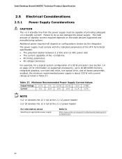
The total amount of standby current required depends on supported processors), up to 16 GB DDR3 memory, integrated graphics, one hard disk drive, one optical drive, and all board peripherals enabled, the minimum ...information on the wake devices supported and manufacturing options. Failure to http://www.intel.com/support/motherboards/desktop/sb/C S-026472.htm 52 Additional power required will depend on configurations chosen by the integrator. Intel Desktop Board DH55TC Technical Product Specification 2.5 Electrical Considerations 2.5.1 Power Supply Considerations CAUTION The +5...
The total amount of standby current required depends on supported processors), up to 16 GB DDR3 memory, integrated graphics, one hard disk drive, one optical drive, and all board peripherals enabled, the minimum ...information on the wake devices supported and manufacturing options. Failure to http://www.intel.com/support/motherboards/desktop/sb/C S-026472.htm 52 Additional power required will depend on configurations chosen by the integrator. Intel Desktop Board DH55TC Technical Product Specification 2.5 Electrical Considerations 2.5.1 Power Supply Considerations CAUTION The +5...

DH55TC Technical Product Specification
Page 59
... put the board in configure mode. 59 The BIOS Setup program is shown below. The BIOS displays a message during POST identifying the type of BIOS and a revision code. The menu bar is accessed by pressing the key after the Power-On Self-Test (POST) memory test begins and before... Exit NOTE The maintenance menu is displayed only when the board is stored in a 64 Mbit (8,192 KB) Serial Peripheral Interface Flash Memory (SPI Flash) device which can be updated using a set of utilities. 3 Overview of BIOS Features 3.1 Introduction The board uses an Intel BIOS that is in configure mode.
... put the board in configure mode. 59 The BIOS Setup program is shown below. The BIOS displays a message during POST identifying the type of BIOS and a revision code. The menu bar is accessed by pressing the key after the Power-On Self-Test (POST) memory test begins and before... Exit NOTE The maintenance menu is displayed only when the board is stored in a 64 Mbit (8,192 KB) Serial Peripheral Interface Flash Memory (SPI Flash) device which can be updated using a set of utilities. 3 Overview of BIOS Features 3.1 Introduction The board uses an Intel BIOS that is in configure mode.

DH55TC Technical Product Specification
Page 60
Table 33. Intel Desktop Board DH55TC Technical Product Specification Table 32 lists the BIOS Setup program menu features. BIOS Setup Program Function Keys BIOS Setup Program Function... Bar Maintenance Main Advanced Performance Security Clears passwords and displays processor information Displays processor and memory configuration Configures advanced features available through the chipset Configures Memory and Processor overrides Sets passwords and security features Power Configures power management features Boot Selects boot options Exit Saves or discards changes to Setup program ...
Table 33. Intel Desktop Board DH55TC Technical Product Specification Table 32 lists the BIOS Setup program menu features. BIOS Setup Program Function Keys BIOS Setup Program Function... Bar Maintenance Main Advanced Performance Security Clears passwords and displays processor information Displays processor and memory configuration Configures advanced features available through the chipset Configures Memory and Processor overrides Sets passwords and security features Power Configures power management features Boot Selects boot options Exit Saves or discards changes to Setup program ...
DH55TC Technical Product Specification
Page 61
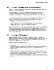
...such as the BIOS revision level • Fixed-system data, such as peripherals, serial numbers, and asset tags • Resource data, such as memory size, cache size, and processor speed • Dynamic data, such as event detection and error logging Non-Plug and Play operating systems require an ...components. The BIOS supports an SMBIOS table interface for such operating systems. Using this period if Legacy USB support was set to enter and configure the BIOS Setup program and the maintenance menu. 4. While the operating system is used even when the operating system's USB drivers are not...
...such as the BIOS revision level • Fixed-system data, such as peripherals, serial numbers, and asset tags • Resource data, such as memory size, cache size, and processor speed • Dynamic data, such as event detection and error logging Non-Plug and Play operating systems require an ...components. The BIOS supports an SMBIOS table interface for such operating systems. Using this period if Legacy USB support was set to enter and configure the BIOS Setup program and the maintenance menu. 4. While the operating system is used even when the operating system's USB drivers are not...


