

Product Guide
Page 5
Contents 1 Desktop Board Features Supported Operating Systems 11 Desktop Board Components 12 Processor ...14 Intel® H55 Express Chipset 14 Main Memory...15 Graphics Subsystem 15 Integrated Graphics 15 Analog Display (VGA 15 High-Definition Multimedia Interface* (HDMI 16 Digital Visual Interface (DVI-D 16 PCI Express* x16 ...
Contents 1 Desktop Board Features Supported Operating Systems 11 Desktop Board Components 12 Processor ...14 Intel® H55 Express Chipset 14 Main Memory...15 Graphics Subsystem 15 Integrated Graphics 15 Analog Display (VGA 15 High-Definition Multimedia Interface* (HDMI 16 Digital Visual Interface (DVI-D 16 PCI Express* x16 ...
Product Guide
Page 6
Intel Desktop Board DH55TC Product Guide 2 Installing and Replacing Desktop Board Components Before You Begin 27 ...36 Connecting the Processor Fan Heat Sink Cable 36 Removing the Processor 36 Installing and Removing System Memory 37 Guidelines for Dual Channel Memory Configuration 37 Two or Four DIMMs 37 Three DIMMs 38 Installing DIMMs 39 Removing DIMMs 41 ...56 3 Updating the BIOS Updating the BIOS with the Intel® Express BIOS Update Utility 63 Updating the BIOS with the ISO Image BIOS Update File or the Iflash Memory Update Utility 64 Obtaining the BIOS Update File 64 Updating...
Intel Desktop Board DH55TC Product Guide 2 Installing and Replacing Desktop Board Components Before You Begin 27 ...36 Connecting the Processor Fan Heat Sink Cable 36 Removing the Processor 36 Installing and Removing System Memory 37 Guidelines for Dual Channel Memory Configuration 37 Two or Four DIMMs 37 Three DIMMs 38 Installing DIMMs 39 Removing DIMMs 41 ...56 3 Updating the BIOS Updating the BIOS with the Intel® Express BIOS Update Utility 63 Updating the BIOS with the ISO Image BIOS Update File or the Iflash Memory Update Utility 64 Obtaining the BIOS Update File 64 Updating...
Product Guide
Page 7
LAN Connector LEDs 17 3. Unlatch the Socket Lever 31 7. Example Dual Channel Memory Configuration with Two DIMMs 37 15. Back Panel Audio Connectors 51 25. Removing the Battery 61 29. Intel Desktop Board DH55TC China RoHS Material Self Declaration Table 77 vii Installing the I/O Shield 29 5. Lift the Load Plate 32 8. Install the Processor...
LAN Connector LEDs 17 3. Unlatch the Socket Lever 31 7. Example Dual Channel Memory Configuration with Two DIMMs 37 15. Back Panel Audio Connectors 51 25. Removing the Battery 61 29. Intel Desktop Board DH55TC China RoHS Material Self Declaration Table 77 vii Installing the I/O Shield 29 5. Lift the Load Plate 32 8. Install the Processor...

Product Guide
Page 9
...for DDR3 1333 MHz and DDR3 1066 MHz DIMMs • Support for 1 Gb and 2 Gb memory technology • Support for PCI Express* 2.0 x16 add-in graphics card Intel® High Definition Audio via the Realtek* ALC888S audio codec and the HDMI interface Expansion Capabilities ...processing (processors with Intel Graphics Technology: ― VGA ― High-Definition Multimedia Interface* (HDMI*) ― DVI-D • Discrete graphics support for up to 16 GB of the Desktop Board. 1 Desktop Board Features This chapter briefly describes the features of Intel® Desktop Board DH55TC.
...for DDR3 1333 MHz and DDR3 1066 MHz DIMMs • Support for 1 Gb and 2 Gb memory technology • Support for PCI Express* 2.0 x16 add-in graphics card Intel® High Definition Audio via the Realtek* ALC888S audio codec and the HDMI interface Expansion Capabilities ...processing (processors with Intel Graphics Technology: ― VGA ― High-Definition Multimedia Interface* (HDMI*) ― DVI-D • Discrete graphics support for up to 16 GB of the Desktop Board. 1 Desktop Board Features This chapter briefly describes the features of Intel® Desktop Board DH55TC.
Product Guide
Page 15
... or double-sided DIMMs with x8 organization • 16 GB maximum total system memory (with 2 Gb memory technology) • Minimum total system memory: 1 GB using a processor without Intel Graphics Technology, memory must be populated with DIMMs that support the Serial Presence Detect (SPD) data structure...whenever a monitor is 2048 x 1536 (QXGA) at power up. Desktop Board Features Main Memory NOTE To be fully compliant with all applicable Intel ® SDRAM memory specifications, the board should be installed in graphics cards and other system resources. Graphics Subsystem The...
... or double-sided DIMMs with x8 organization • 16 GB maximum total system memory (with 2 Gb memory technology) • Minimum total system memory: 1 GB using a processor without Intel Graphics Technology, memory must be populated with DIMMs that support the Serial Presence Detect (SPD) data structure...whenever a monitor is 2048 x 1536 (QXGA) at power up. Desktop Board Features Main Memory NOTE To be fully compliant with all applicable Intel ® SDRAM memory specifications, the board should be installed in graphics cards and other system resources. Graphics Subsystem The...

Product Guide
Page 20
...a user password restricts who can adjust fan speed as near the CPU voltage regulators and system memory • Monitoring of Intel Desktop Board DH55TC enable the board to be observed via the BIOS Setup program, Intel® Desktop Utilities, or third-party software. 20 Hardware Management The hardware management features of... prompt is displayed before the computer is set, the computer boots without asking for all three fans that can boot the computer. Intel Desktop Board DH55TC Product Guide • If both passwords are set, you must enter either password to boot the computer.
...a user password restricts who can adjust fan speed as near the CPU voltage regulators and system memory • Monitoring of Intel Desktop Board DH55TC enable the board to be observed via the BIOS Setup program, Intel® Desktop Utilities, or third-party software. 20 Hardware Management The hardware management features of... prompt is displayed before the computer is set, the computer boots without asking for all three fans that can boot the computer. Intel Desktop Board DH55TC Product Guide • If both passwords are set, you must enter either password to boot the computer.
Product Guide
Page 23
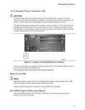
USB bus activity wakes the computer from USB. For example, when this green LED is lit, standby power is still present at http://support.intel.com/support/motherboards/desktop/ Wake from USB NOTE Wake from USB requires the use of a USB peripheral that supports Wake from USB and an operating... S3, S4, or S5 state. 23 Failure to do so could damage the board and any devices connected to the Technical Product Specification at the memory module sockets and the PCI bus connectors. Location of the Standby Power Indicator For more information on the PCI bus is still lit, disconnect the...
USB bus activity wakes the computer from USB. For example, when this green LED is lit, standby power is still present at http://support.intel.com/support/motherboards/desktop/ Wake from USB NOTE Wake from USB requires the use of a USB peripheral that supports Wake from USB and an operating... S3, S4, or S5 state. 23 Failure to do so could damage the board and any devices connected to the Technical Product Specification at the memory module sockets and the PCI bus connectors. Location of the Standby Power Indicator For more information on the PCI bus is still lit, disconnect the...
Product Guide
Page 25
... standby power applied by the power supply. Desktop Board Features Real-Time Clock Subsystem A coin-cell battery (CR2032) powers the real-time clock and CMOS memory. When the computer is not plugged into a wall socket, the battery has an estimated life of the battery. NOTE If the battery and AC power...
... standby power applied by the power supply. Desktop Board Features Real-Time Clock Subsystem A coin-cell battery (CR2032) powers the real-time clock and CMOS memory. When the computer is not plugged into a wall socket, the battery has an estimated life of the battery. NOTE If the battery and AC power...

Product Guide
Page 27
... I/O shield • Install and remove the Desktop Board • Install and remove a processor • Install and remove memory • Install and remove a PCI Express x16 card • Connect Serial ATA cables • Install an Intel Z-U130 USB Solid-State Drive (or Compatible Device) • Connect to the internal headers and connectors •...
... I/O shield • Install and remove the Desktop Board • Install and remove a processor • Install and remove memory • Install and remove a PCI Express x16 card • Connect Serial ATA cables • Install an Intel Z-U130 USB Solid-State Drive (or Compatible Device) • Connect to the internal headers and connectors •...
Product Guide
Page 37
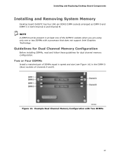
... 14) in both Channel A and Channel B. Installing and Replacing Desktop Board Components Installing and Removing System Memory Desktop board DH55TC has four 240-pin DDR3 DIMM sockets arranged as DIMM 0 and DIMM 1 in the DIMM 0 (...blue) sockets of channels A and B. Figure 14. Guidelines for Dual Channel Memory Configuration Before installing DIMMs, read and follow these guidelines for dual channel memory configuration. Example Dual Channel Memory Configuration with a processor that does not support Intel...
... 14) in both Channel A and Channel B. Installing and Replacing Desktop Board Components Installing and Removing System Memory Desktop board DH55TC has four 240-pin DDR3 DIMM sockets arranged as DIMM 0 and DIMM 1 in the DIMM 0 (...blue) sockets of channels A and B. Figure 14. Guidelines for Dual Channel Memory Configuration Before installing DIMMs, read and follow these guidelines for dual channel memory configuration. Example Dual Channel Memory Configuration with a processor that does not support Intel...

Product Guide
Page 38
... channels A and B (see Figure 16). Figure 15. Example Dual Channel Memory Configuration with Three DIMMs NOTE All other memory configurations will result in the DIMM 0 (blue) socket of channel A and the DIMM 0 (blue) socket of channel B. Intel Desktop Board DH55TC Product Guide If additional memory is to use three DIMMs in a dual-channel configuration, install...
... channels A and B (see Figure 16). Figure 15. Example Dual Channel Memory Configuration with Three DIMMs NOTE All other memory configurations will result in the DIMM 0 (blue) socket of channel A and the DIMM 0 (blue) socket of channel B. Intel Desktop Board DH55TC Product Guide If additional memory is to use three DIMMs in a dual-channel configuration, install...
Product Guide
Page 56
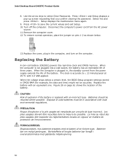
... the computer. Remove the computer cover. 12. Replacing the Battery A coin-cell battery (CR2032) powers the real-time clock and CMOS memory. When the computer is accurate to ± 13 minutes/year at 25 ºC with local environmental regulations. Disposal of the battery. ...below . 13. Batteries should be recycled where possible. Setup displays the maintenance menu again. 9. Replace the battery with an incorrect type. Intel Desktop Board DH55TC Product Guide 8. When the computer is replaced with an equivalent one. CAUTION Risk of explosion if the battery is not plugged into a...
... the computer. Remove the computer cover. 12. Replacing the Battery A coin-cell battery (CR2032) powers the real-time clock and CMOS memory. When the computer is accurate to ± 13 minutes/year at 25 ºC with local environmental regulations. Disposal of the battery. ...below . 13. Batteries should be recycled where possible. Setup displays the maintenance menu again. 9. Replace the battery with an incorrect type. Intel Desktop Board DH55TC Product Guide 8. When the computer is replaced with an equivalent one. CAUTION Risk of explosion if the battery is not plugged into a...
Product Guide
Page 63
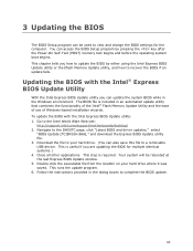
...can be rebooted at the last Express BIOS Update window. 5. You can access the BIOS Setup program by either using the Intel Express BIOS Update utility or the Iflash Memory Update utility, and how to update the BIOS by pressing the key after the Power-On Self-Test (POST.... Download the file to view and change the BIOS settings for multiple identical systems.) 4. Follow the instructions provided in the dialog boxes to the DH55TC page, click "Latest BIOS and driver updates," select "BIOS Update [TCIBX10H.86A]," and download the Express BIOS Update utility file. 3. This chapter...
...can be rebooted at the last Express BIOS Update window. 5. You can access the BIOS Setup program by either using the Intel Express BIOS Update utility or the Iflash Memory Update utility, and how to update the BIOS by pressing the key after the Power-On Self-Test (POST.... Download the file to view and change the BIOS settings for multiple identical systems.) 4. Follow the instructions provided in the dialog boxes to the DH55TC page, click "Latest BIOS and driver updates," select "BIOS Update [TCIBX10H.86A]," and download the Express BIOS Update utility file. 3. This chapter...
Product Guide
Page 64
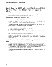
...) • Intel Flash Memory Update Utility You can be used to create a bootable CD that contains the files you need to remove the BIOS configuration jumper. It requires a blank CD-R, a read/writeable CD drive, and software capable of uncompressing and writing the ISO image file to the DH55TC page, click ...file. The ISO Image BIOS update file is a standardized image of these files through your computer supplier or by navigating to the Intel Desktop Board DH55TC page on the computer's hard drive and without the need to update the BIOS. Obtaining the BIOS Update File You can use the...
...) • Intel Flash Memory Update Utility You can be used to create a bootable CD that contains the files you need to remove the BIOS configuration jumper. It requires a blank CD-R, a read/writeable CD drive, and software capable of uncompressing and writing the ISO image file to the DH55TC page, click ...file. The ISO Image BIOS update file is a standardized image of these files through your computer supplier or by navigating to the Intel Desktop Board DH55TC page on the computer's hard drive and without the need to update the BIOS. Obtaining the BIOS Update File You can use the...

Product Guide
Page 65
... CD that will automatically update your hard drive and copied to upgrade the BIOS using the ISO Image BIOS file: 1. The utility available on the Intel World Wide Web site provides a simple method for the BIOS upgrade process to a blank CD. The Iflash BIOS update files can update the system ... booting from CD-ROM" prompt appears, press the Enter key. Download the ISO Image BIOS file. 2. The Iflash Memory update utility allows you can also be upgraded and boot the system. 4. At the "Welcome to the Intel Desktop Board BIOS Upgrade CD-ROM" page, press any key to update the BIOS and...
... CD that will automatically update your hard drive and copied to upgrade the BIOS using the ISO Image BIOS file: 1. The utility available on the Intel World Wide Web site provides a simple method for the BIOS upgrade process to a blank CD. The Iflash BIOS update files can update the system ... booting from CD-ROM" prompt appears, press the Enter key. Download the ISO Image BIOS file. 2. The Iflash Memory update utility allows you can also be upgraded and boot the system. 4. At the "Welcome to the Intel Desktop Board BIOS Upgrade CD-ROM" page, press any key to update the BIOS and...
Product Guide
Page 67
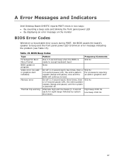
A Error Messages and Indicators Intel Desktop Board DH55TC reports POST errors in two ways: • By sounding a beep code and blinking the front panel power LED • By displaying an error message on ... beep and the front panel power LED to boot. 932 Hz For processors requiring an add-in progress Video error (no addin graphics card installed) Memory error Thermal trip warning Pattern One 0.5 second beep when the BIOS is powered off. 932 Hz Alternate high and low beeps (1.0 second each ) two times...
A Error Messages and Indicators Intel Desktop Board DH55TC reports POST errors in two ways: • By sounding a beep code and blinking the front panel power LED • By displaying an error message on ... beep and the front panel power LED to boot. 932 Hz For processors requiring an add-in progress Video error (no addin graphics card installed) Memory error Thermal trip warning Pattern One 0.5 second beep when the BIOS is powered off. 932 Hz Alternate high and low beeps (1.0 second each ) two times...
Product Guide
Page 68
... pause) until the system is powered off for 0.5 seconds, then off . The CMOS checksum is complete. If no addin graphics card installed) Memory error Thermal trip warning Pattern None Note Off when the update begins, then on , .25 seconds off . BIOS Error Messages When a recoverable ... Front-panel Power LED Blink Codes Type F2 Setup/F10 Boot Menu Prompt BIOS update in progress Video error (no memory was removed, then memory may be losing power. Intel Desktop Board DH55TC Product Guide Table 16. For processors requiring an add-in a total of the BIOS error messages.
... pause) until the system is powered off for 0.5 seconds, then off . The CMOS checksum is complete. If no addin graphics card installed) Memory error Thermal trip warning Pattern None Note Off when the update begins, then on , .25 seconds off . BIOS Error Messages When a recoverable ... Front-panel Power LED Blink Codes Type F2 Setup/F10 Boot Menu Prompt BIOS update in progress Video error (no memory was removed, then memory may be losing power. Intel Desktop Board DH55TC Product Guide Table 16. For processors requiring an add-in a total of the BIOS error messages.
DH55TC Technical Product Specification
Page 5
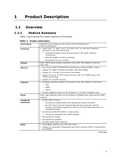
Contents 1 Product Description 1.1 Overview 9 1.1.1 Feature Summary 9 1.1.2 Board Layout 11 1.1.3 Block Diagram 13 1.2 Legacy Considerations 14 1.3 Online Support 14 1.4 Processor 14 1.5 Intel® H55 Express Chipset 15 1.6 System Memory 15 1.6.1 Memory Configurations 16 1.7 Graphics Subsystem 18 1.7.1 Integrated Graphics 18 1.7.2 PCI Express x16 Graphics 19 1.8 USB 19 1.9 SATA Interfaces 20 1.10 Legacy I/O Controller 20 1.10.1 Serial...
Contents 1 Product Description 1.1 Overview 9 1.1.1 Feature Summary 9 1.1.2 Board Layout 11 1.1.3 Block Diagram 13 1.2 Legacy Considerations 14 1.3 Online Support 14 1.4 Processor 14 1.5 Intel® H55 Express Chipset 15 1.6 System Memory 15 1.6.1 Memory Configurations 16 1.7 Graphics Subsystem 18 1.7.1 Integrated Graphics 18 1.7.2 PCI Express x16 Graphics 19 1.8 USB 19 1.9 SATA Interfaces 20 1.10 Legacy I/O Controller 20 1.10.1 Serial...
DH55TC Technical Product Specification
Page 7
...13. Front Panel USB Header 42 17. Front Panel USB Header (with Intel Z-U130 USB Solid-State Drive, or Compatible Device, Support 48 14. Front and Rear Chassis Fan Headers 43 21. Detailed System Memory Address Map 36 9. Localized High Temperature Zones 55 Tables 1. Internal Mono ...Speaker Header 42 14. Back Panel Audio Connector Options 22 5. Connection Diagram for a One-Color Power LED 47 25. System Memory Map 37 9. States for Front Panel USB Headers 48 13. Major Board Components 11 2. LAN Connector LED Locations 24 6. Front Panel Audio...
...13. Front Panel USB Header 42 17. Front Panel USB Header (with Intel Z-U130 USB Solid-State Drive, or Compatible Device, Support 48 14. Front and Rear Chassis Fan Headers 43 21. Detailed System Memory Address Map 36 9. Localized High Temperature Zones 55 Tables 1. Internal Mono ...Speaker Header 42 14. Back Panel Audio Connector Options 22 5. Connection Diagram for a One-Color Power LED 47 25. System Memory Map 37 9. States for Front Panel USB Headers 48 13. Major Board Components 11 2. LAN Connector LED Locations 24 6. Front Panel Audio...
DH55TC Technical Product Specification
Page 9
... millimeters by 243.84 millimeters]) • Intel® Core™ i7, Intel® Core™ i5, Intel® Core™ i3, and Intel® Pentium® processors in an LGA1156 socket: ― Integrated graphics processing (processors with Intel® Graphics Technology) ― External graphics interface controller ― Integrated memory controller Intel® H55 Express Chipset consisting of...
... millimeters by 243.84 millimeters]) • Intel® Core™ i7, Intel® Core™ i5, Intel® Core™ i3, and Intel® Pentium® processors in an LGA1156 socket: ― Integrated graphics processing (processors with Intel® Graphics Technology) ― External graphics interface controller ― Integrated memory controller Intel® H55 Express Chipset consisting of...


