
Product Guide
Page 5
Contents 1 Desktop Board Features Supported Operating Systems 11 Desktop Board Components 12 Processor ...14 Intel® H55 Express Chipset 14 Main Memory...15 Graphics Subsystem 15 Integrated Graphics 15 Analog Display (VGA 15 High-Definition Multimedia Interface* (HDMI 16 Digital Visual Interface (DVI-D 16 PCI Express* x16 ...
Contents 1 Desktop Board Features Supported Operating Systems 11 Desktop Board Components 12 Processor ...14 Intel® H55 Express Chipset 14 Main Memory...15 Graphics Subsystem 15 Integrated Graphics 15 Analog Display (VGA 15 High-Definition Multimedia Interface* (HDMI 16 Digital Visual Interface (DVI-D 16 PCI Express* x16 ...

Product Guide
Page 6
Intel Desktop Board DH55HC Product Guide 2 Installing and Replacing Desktop Board Components Before You Begin 27 ...36 Connecting the Processor Fan Heat Sink Cable 36 Removing the Processor 36 Installing and Removing System Memory 37 Guidelines for Dual Channel Memory Configuration 37 Two or Four DIMMs 37 Three DIMMs 38 Installing DIMMs 39 Removing DIMMs 41 ...57 3 Updating the BIOS Updating the BIOS with the Intel® Express BIOS Update Utility 63 Updating the BIOS with the ISO Image BIOS Update File or the Iflash Memory Update Utility 64 Obtaining the BIOS Update File 64 Updating...
Intel Desktop Board DH55HC Product Guide 2 Installing and Replacing Desktop Board Components Before You Begin 27 ...36 Connecting the Processor Fan Heat Sink Cable 36 Removing the Processor 36 Installing and Removing System Memory 37 Guidelines for Dual Channel Memory Configuration 37 Two or Four DIMMs 37 Three DIMMs 38 Installing DIMMs 39 Removing DIMMs 41 ...57 3 Updating the BIOS Updating the BIOS with the Intel® Express BIOS Update Utility 63 Updating the BIOS with the ISO Image BIOS Update File or the Iflash Memory Update Utility 64 Obtaining the BIOS Update File 64 Updating...
Product Guide
Page 7
...35 13. Example Dual Channel Memory Configuration with Three DIMMs 38 17. Installing an Intel Z-U130 USB Solid-State Drive (or Compatible Device 45 23. Intel Desktop Board DH55HC Components 12 2. Back Panel Audio Connectors 52 25. Intel Desktop Board DH55HC China RoHS Material Self Declaration...Level Certification Markings 80 Chassis and Component Certifications 81 Figures 1. Installing a DIMM 40 19. Remove the Socket Cover 33 9. Intel Desktop Board DH55HC Mounting Screw Hole Locations 30 6. Use DDR3 DIMMs 39 18. Installing a PCI Express x16 Graphics Card 42 20. Unlatch ...
...35 13. Example Dual Channel Memory Configuration with Three DIMMs 38 17. Installing an Intel Z-U130 USB Solid-State Drive (or Compatible Device 45 23. Intel Desktop Board DH55HC Components 12 2. Back Panel Audio Connectors 52 25. Intel Desktop Board DH55HC China RoHS Material Self Declaration...Level Certification Markings 80 Chassis and Component Certifications 81 Figures 1. Installing a DIMM 40 19. Remove the Socket Cover 33 9. Intel Desktop Board DH55HC Mounting Screw Hole Locations 30 6. Use DDR3 DIMMs 39 18. Installing a PCI Express x16 Graphics Card 42 20. Unlatch ...
Product Guide
Page 9
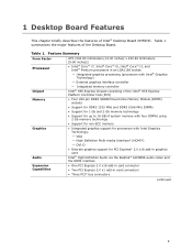
...an LGA1156 socket: ― Integrated graphics processing (processors with Intel® Graphics Technology) ― External graphics interface controller ― Integrated memory controller Intel® H55 Express Chipset consisting of the Intel® H55 Express Platform Controller Hub (PCH) • ... Intel® Core™ i7, Intel® Core™ i5, Intel® Core™ i3, and Intel® Pentium processors in card connectors • Three PCI* bus connectors continued 9 1 Desktop Board Features This chapter briefly describes the features of Intel® Desktop Board DH55HC....
...an LGA1156 socket: ― Integrated graphics processing (processors with Intel® Graphics Technology) ― External graphics interface controller ― Integrated memory controller Intel® H55 Express Chipset consisting of the Intel® H55 Express Platform Controller Hub (PCH) • ... Intel® Core™ i7, Intel® Core™ i5, Intel® Core™ i3, and Intel® Pentium processors in card connectors • Three PCI* bus connectors continued 9 1 Desktop Board Features This chapter briefly describes the features of Intel® Desktop Board DH55HC....
Product Guide
Page 15
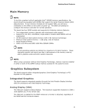
...sided or double-sided DIMMs with x8 organization • 16 GB maximum total system memory (with 2 Gb memory technology) • Minimum total system memory: 1 GB using a processor without Intel Graphics Technology, memory must be populated with DIMMs that support the Serial Presence Detect (SPD) data structure.... The VGA port is 2048 x 1536 (QXGA) at power up. Desktop Board Features Main Memory NOTE To be fully compliant with all applicable Intel ® SDRAM memory specifications, the board should be installed in graphics cards and other system resources. NOTE When using 1...
...sided or double-sided DIMMs with x8 organization • 16 GB maximum total system memory (with 2 Gb memory technology) • Minimum total system memory: 1 GB using a processor without Intel Graphics Technology, memory must be populated with DIMMs that support the Serial Presence Detect (SPD) data structure.... The VGA port is 2048 x 1536 (QXGA) at power up. Desktop Board Features Main Memory NOTE To be fully compliant with all applicable Intel ® SDRAM memory specifications, the board should be installed in graphics cards and other system resources. NOTE When using 1...
Product Guide
Page 20
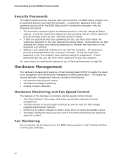
...on page 56. Hardware Management The hardware management features of Intel Desktop Board DH55HC enable the board to be accessed and who can be set , the computer boots without asking for a password. Intel Desktop Board DH55HC Product Guide Security Passwords The BIOS includes security features that... can adjust fan speed as near the CPU voltage regulators and system memory • Monitoring of Setup gives the user restricted access to...
...on page 56. Hardware Management The hardware management features of Intel Desktop Board DH55HC enable the board to be accessed and who can be set , the computer boots without asking for a password. Intel Desktop Board DH55HC Product Guide Security Passwords The BIOS includes security features that... can adjust fan speed as near the CPU voltage regulators and system memory • Monitoring of Setup gives the user restricted access to...
Product Guide
Page 23
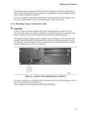
... lit when there is standby power still present on standby current requirements for the Desktop Board, refer to the Technical Product Specification at the memory module sockets and the PCI bus connectors. Add-in power management and can be off and the standby power indicator is still present at ...http://support.intel.com/support/motherboards/desktop/ 23 For example, when this specification can participate in cards that support this green LED is lit, standby power ...
... lit when there is standby power still present on standby current requirements for the Desktop Board, refer to the Technical Product Specification at the memory module sockets and the PCI bus connectors. Add-in power management and can be off and the standby power indicator is still present at ...http://support.intel.com/support/motherboards/desktop/ 23 For example, when this specification can participate in cards that support this green LED is lit, standby power ...

Product Guide
Page 25
...; 13 minutes/year at 25 ºC with an equivalent one. Real-Time Clock Subsystem A coin-cell battery (CR2032) powers the real-time clock and CMOS memory. The clock is not plugged into a wall socket, the battery has an estimated life of three years. When the computer is accurate to page 57...
...; 13 minutes/year at 25 ºC with an equivalent one. Real-Time Clock Subsystem A coin-cell battery (CR2032) powers the real-time clock and CMOS memory. The clock is not plugged into a wall socket, the battery has an estimated life of three years. When the computer is accurate to page 57...
Product Guide
Page 27
... I/O shield • Install and remove the Desktop Board • Install and remove a processor • Install and remove memory • Install and remove a PCI Express x16 card • Connect Serial ATA cables • Install an Intel Z-U130 USB Solid-State Drive (or Compatible Device) • Connect to the internal headers and connectors •...
... I/O shield • Install and remove the Desktop Board • Install and remove a processor • Install and remove memory • Install and remove a PCI Express x16 card • Connect Serial ATA cables • Install an Intel Z-U130 USB Solid-State Drive (or Compatible Device) • Connect to the internal headers and connectors •...
Product Guide
Page 37
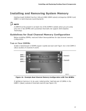
... matched pair of DIMMs equal in speed and size (see Figure 15). 37 Installing and Replacing Desktop Board Components Installing and Removing System Memory Desktop board DH55HC has four 240-pin DDR3 DIMM sockets arranged as DIMM 0 and DIMM 1 in the DIMM 0 (blue) sockets of channels A ...Memory Configuration Before installing DIMMs, read and follow these guidelines for dual channel memory configuration. NOTE A DIMM must be used, install another matched pair of DIMMs in at least one of the DIMM 0 sockets when you are using only one or two DIMMs with a processor that does not support Intel...
... matched pair of DIMMs equal in speed and size (see Figure 15). 37 Installing and Replacing Desktop Board Components Installing and Removing System Memory Desktop board DH55HC has four 240-pin DDR3 DIMM sockets arranged as DIMM 0 and DIMM 1 in the DIMM 0 (blue) sockets of channels A ...Memory Configuration Before installing DIMMs, read and follow these guidelines for dual channel memory configuration. NOTE A DIMM must be used, install another matched pair of DIMMs in at least one of the DIMM 0 sockets when you are using only one or two DIMMs with a processor that does not support Intel...

Product Guide
Page 38
Install the third DIMM in single channel memory operation. 38 Example Dual Channel Memory Configuration with Four DIMMs Three DIMMs If you want to use three DIMMs in a dual-channel configuration, install a matched pair of DIMMs equal in speed and size in the DIMM 0 (blue) socket of channel A and the DIMM 0 (blue) socket of either channel A or channel B (see Figure 16). Intel Desktop Board DH55HC Product Guide Figure 15. Figure 16. Example Dual Channel Memory Configuration with Three DIMMs NOTE All other memory configurations will result in the DIMM 1 (black) socket of channel B.
Install the third DIMM in single channel memory operation. 38 Example Dual Channel Memory Configuration with Four DIMMs Three DIMMs If you want to use three DIMMs in a dual-channel configuration, install a matched pair of DIMMs equal in speed and size in the DIMM 0 (blue) socket of channel A and the DIMM 0 (blue) socket of either channel A or channel B (see Figure 16). Intel Desktop Board DH55HC Product Guide Figure 15. Figure 16. Example Dual Channel Memory Configuration with Three DIMMs NOTE All other memory configurations will result in the DIMM 1 (black) socket of channel B.

Product Guide
Page 57
... computer. To restore normal operation, place the jumper on the computer. Replacing the Battery A coin-cell battery (CR2032) powers the real-time clock and CMOS memory. FORHOLDSREGEL Eksplosionsfare, hvis batteriet erstattes med et batteri af en forkert type. Remove the computer cover. 12. Batteries should be accurate. Bortskaffelse af brugte batterier...
... computer. To restore normal operation, place the jumper on the computer. Replacing the Battery A coin-cell battery (CR2032) powers the real-time clock and CMOS memory. FORHOLDSREGEL Eksplosionsfare, hvis batteriet erstattes med et batteri af en forkert type. Remove the computer cover. 12. Batteries should be accurate. Bortskaffelse af brugte batterier...
Product Guide
Page 63
...and change the BIOS settings for multiple identical systems.) 4. Follow the instructions provided in an automated update utility that combines the functionality of the Intel® Flash Memory Update Utility and the ease of use of Windows-based installation wizards. To update the BIOS with the... Express BIOS Update Utility With the Intel Express BIOS Update utility you how to update the BIOS by pressing the key after the Power-On Self-Test (POST) memory test begins and before the operating system boot begins. The BIOS file is required. Go to the DH55HC page, click "Latest BIOS and ...
...and change the BIOS settings for multiple identical systems.) 4. Follow the instructions provided in an automated update utility that combines the functionality of the Intel® Flash Memory Update Utility and the ease of use of Windows-based installation wizards. To update the BIOS with the... Express BIOS Update Utility With the Intel Express BIOS Update utility you how to update the BIOS by pressing the key after the Power-On Self-Test (POST) memory test begins and before the operating system boot begins. The BIOS file is required. Go to the DH55HC page, click "Latest BIOS and ...
Product Guide
Page 64
... the BIOS using the ISO Image BIOS update file (recommended), or Iflash BIOS update file. Intel Desktop Board DH55HC Product Guide Updating the BIOS with the ISO Image BIOS Update File or the Iflash Memory Update Utility You can update to a new version of the BIOS by navigating to the... Intel Desktop Board DH55HC page on the Intel World Wide Web site at: http://support.intel.com/support/motherboards/desktop Navigate to the DH55HC page, click "Latest BIOS and driver ...
... the BIOS using the ISO Image BIOS update file (recommended), or Iflash BIOS update file. Intel Desktop Board DH55HC Product Guide Updating the BIOS with the ISO Image BIOS Update File or the Iflash Memory Update Utility You can update to a new version of the BIOS by navigating to the... Intel Desktop Board DH55HC page on the Intel World Wide Web site at: http://support.intel.com/support/motherboards/desktop Navigate to the DH55HC page, click "Latest BIOS and driver ...
Product Guide
Page 66
... Review the instructions distributed with the .BIO file in the root directory will be damaged. Intel Desktop Board DH55HC Product Guide Updating the BIOS with the Iflash Memory Update Utility With the Iflash Memory update utility you to BIOS size and recovery requirements, a CD-R with the update utility before attempting... USB media. 2. Uncompress the BIOS update file and copy the .BIO file, IFLASH.EXE, and .ITK file (optional) to http://support.intel.com/support/motherboards/desktop/sb/CS-022312.htm 66 Manually run the IFLASH.EXE file from a BIOS update failure, go to a bootable USB...
... Review the instructions distributed with the .BIO file in the root directory will be damaged. Intel Desktop Board DH55HC Product Guide Updating the BIOS with the Iflash Memory Update Utility With the Iflash Memory update utility you to BIOS size and recovery requirements, a CD-R with the update utility before attempting... USB media. 2. Uncompress the BIOS update file and copy the .BIO file, IFLASH.EXE, and .ITK file (optional) to http://support.intel.com/support/motherboards/desktop/sb/CS-022312.htm 66 Manually run the IFLASH.EXE file from a BIOS update failure, go to a bootable USB...

Product Guide
Page 67
... 17. BIOS Beep Codes Type F2 Setup/F10 Boot Menu Prompt BIOS update in progress Video error (no addin graphics card installed) Memory error Thermal trip warning Pattern One 0.5 second beep when the BIOS is powered off. 932 Hz Alternate high and low beeps (1.0 second... each ) two times, then a 2.5-second pause (off (1.0 second each ) for eight beeps followed by system shut down. A Error Messages and Indicators Intel Desktop Board DH55HC reports POST errors in graphics card On-off (1.0 second each) three times, then a 2.5-second pause (off), the entire pattern repeats (beeps and pause)...
... 17. BIOS Beep Codes Type F2 Setup/F10 Boot Menu Prompt BIOS update in progress Video error (no addin graphics card installed) Memory error Thermal trip warning Pattern One 0.5 second beep when the BIOS is powered off. 932 Hz Alternate high and low beeps (1.0 second... each ) two times, then a 2.5-second pause (off (1.0 second each ) for eight beeps followed by system shut down. A Error Messages and Indicators Intel Desktop Board DH55HC reports POST errors in graphics card On-off (1.0 second each) three times, then a 2.5-second pause (off), the entire pattern repeats (beeps and pause)...

Product Guide
Page 68
... an error message describing the problem. Table 19 gives an explanation of 16 blinks. Intel Desktop Board DH55HC Product Guide Table 18. Replace the battery soon. If no addin graphics card installed) Memory error Thermal trip warning Pattern None Note Off when the update begins, then on ,... .25 seconds off for 0.5 seconds, then off . CMOS memory may be losing power. Each ...
... an error message describing the problem. Table 19 gives an explanation of 16 blinks. Intel Desktop Board DH55HC Product Guide Table 18. Replace the battery soon. If no addin graphics card installed) Memory error Thermal trip warning Pattern None Note Off when the update begins, then on ,... .25 seconds off for 0.5 seconds, then off . CMOS memory may be losing power. Each ...
Intel Desktop Board DH55HC Technical Product Specification
Page 5
Contents 1 Product Description 1.1 Overview 9 1.1.1 Feature Summary 9 1.1.2 Board Layout 11 1.1.3 Block Diagram 13 1.2 Legacy Considerations 14 1.3 Online Support 14 1.4 Processor 14 1.5 Intel® H55 Express Chipset 15 1.6 System Memory 15 1.6.1 Memory Configurations 16 1.7 Graphics Subsystem 18 1.7.1 Integrated Graphics 18 1.7.2 PCI Express x16 Graphics 19 1.8 USB 19 1.9 SATA Interfaces 20 1.10 Legacy I/O Controller 20 1.10.1 Serial...
Contents 1 Product Description 1.1 Overview 9 1.1.1 Feature Summary 9 1.1.2 Board Layout 11 1.1.3 Block Diagram 13 1.2 Legacy Considerations 14 1.3 Online Support 14 1.4 Processor 14 1.5 Intel® H55 Express Chipset 15 1.6 System Memory 15 1.6.1 Memory Configurations 16 1.7 Graphics Subsystem 18 1.7.1 Integrated Graphics 18 1.7.2 PCI Express x16 Graphics 19 1.8 USB 19 1.9 SATA Interfaces 20 1.10 Legacy I/O Controller 20 1.10.1 Serial...
Intel Desktop Board DH55HC Technical Product Specification
Page 7
...Fan Headers 26 7. Location of the Jumper Block 49 15. Connection Diagram for Front Panel USB Headers 48 13. Board Dimensions 51 16. Supported Memory Configurations 15 4. LAN Connector LED States 24 5. Chassis Intrusion Header 43 20. Processor Core Power Connector 44 24. LAN Connector LED Locations 24 ... Audio 42 15. Location of the Standby Power LED 33 8. Internal Mono Speaker Header 42 14. Front Panel USB Header (with Intel Z-U130 USB Solid-State Drive, or Compatible Device, Support 48 14. Main Power Connector 45 25. Effects of Pressing the Power Switch ...
...Fan Headers 26 7. Location of the Jumper Block 49 15. Connection Diagram for Front Panel USB Headers 48 13. Board Dimensions 51 16. Supported Memory Configurations 15 4. LAN Connector LED States 24 5. Chassis Intrusion Header 43 20. Processor Core Power Connector 44 24. LAN Connector LED Locations 24 ... Audio 42 15. Location of the Standby Power LED 33 8. Internal Mono Speaker Header 42 14. Front Panel USB Header (with Intel Z-U130 USB Solid-State Drive, or Compatible Device, Support 48 14. Main Power Connector 45 25. Effects of Pressing the Power Switch ...

Intel Desktop Board DH55HC Technical Product Specification
Page 9
... DDR3 1333 MHz and DDR3 1066 MHz DIMMs • Support for 1 Gb and 2 Gb memory technology • Support for up to 16 GB of the board. one header supports an Intel Z-U130 USB Solid-State Drive (or compatible device) • Six internal Serial ATA (SATA)...1 Product Description 1.1 Overview 1.1.1 Feature Summary Table 1 summarizes the major features of system memory with four DIMMs using 2 Gb memory technology • Support for non-ECC memory • Integrated graphics support for processors with Intel Graphics Technology: ― VGA ― HDMI ― DVI-D • Discrete graphics ...
... DDR3 1333 MHz and DDR3 1066 MHz DIMMs • Support for 1 Gb and 2 Gb memory technology • Support for up to 16 GB of the board. one header supports an Intel Z-U130 USB Solid-State Drive (or compatible device) • Six internal Serial ATA (SATA)...1 Product Description 1.1 Overview 1.1.1 Feature Summary Table 1 summarizes the major features of system memory with four DIMMs using 2 Gb memory technology • Support for non-ECC memory • Integrated graphics support for processors with Intel Graphics Technology: ― VGA ― HDMI ― DVI-D • Discrete graphics ...


