

Product Specification
Page 2
... property rights. INFORMATION IN THIS DOCUMENT IS PROVIDED IN CONNECTION WITH INTEL® PRODUCTS. Intel® desktop boards may be published in the U.S. Changes to only the standard Intel® Desktop Board DG41TX with BIOS identifier TXG4110H.86A. Copies of the Intel® Desktop Board DG41TX Technical Product Specification Date March 2010 This product specification applies to...
... property rights. INFORMATION IN THIS DOCUMENT IS PROVIDED IN CONNECTION WITH INTEL® PRODUCTS. Intel® desktop boards may be published in the U.S. Changes to only the standard Intel® Desktop Board DG41TX with BIOS identifier TXG4110H.86A. Copies of the Intel® Desktop Board DG41TX Technical Product Specification Date March 2010 This product specification applies to...

Product Specification
Page 3
... of the resources of the board The features supported by the BIOS Setup program A description of the BIOS error messages, beep codes, and POST codes Regulatory compliance and battery disposal information Typographical Conventions This section contains information about the Intel Desktop Board DG41TX and its components to the vendors, system integrators, and other engineers...
... of the resources of the board The features supported by the BIOS Setup program A description of the BIOS error messages, beep codes, and POST codes Regulatory compliance and battery disposal information Typographical Conventions This section contains information about the Intel Desktop Board DG41TX and its components to the vendors, system integrators, and other engineers...

Product Specification
Page 6
Intel Desktop Board DG41TX Technical Product Specification 2.4.1 Form Factor 55 2.5 Electrical Considerations 56 2.5.1 Power Supply Considerations 56 2.5.2 Fan Header Current Capability 57 2.5.3 Add-in Board Considerations 57 2.6 Thermal Considerations 57 2.7 Reliability 59 2.8 Environmental 60 3 Overview of BIOS Features 3.1 Introduction 61 3.2 BIOS Flash Memory Organization 62 3.3 Resource Configuration 62 3.3.1 PCI Autoconfiguration 62 3.3.2 PCI IDE Support 63...
Intel Desktop Board DG41TX Technical Product Specification 2.4.1 Form Factor 55 2.5 Electrical Considerations 56 2.5.1 Power Supply Considerations 56 2.5.2 Fan Header Current Capability 57 2.5.3 Add-in Board Considerations 57 2.6 Thermal Considerations 57 2.7 Reliability 59 2.8 Environmental 60 3 Overview of BIOS Features 3.1 Introduction 61 3.2 BIOS Flash Memory Organization 62 3.3 Resource Configuration 62 3.3.1 PCI Autoconfiguration 62 3.3.2 PCI IDE Support 63...

Product Specification
Page 7
...Indicator LED 36 8. Audio Jack Retasking Support 24 5. Effects of Pressing the Power Switch 30 7. Power States and Targeted System Power 31 8. BIOS Setup Configuration Jumper Settings 54 27. Board Dimensions 55 15. Processor (4-pin) Fan Header 46 15. S/PDIF Header 47 20. Back Panel ...Audio Connector Options 25 5. LAN Connector LED States 27 6. Front and Rear Chassis Fan Headers 46 16. Connection Diagram for Intel HD Audio 47 17. Localized High Temperature Zones 58 Tables 1. Processor Core Power Connector 49 21. Main Power Connector 49 22. LAN ...
...Indicator LED 36 8. Audio Jack Retasking Support 24 5. Effects of Pressing the Power Switch 30 7. Power States and Targeted System Power 31 8. BIOS Setup Configuration Jumper Settings 54 27. Board Dimensions 55 15. Processor (4-pin) Fan Header 46 15. S/PDIF Header 47 20. Back Panel ...Audio Connector Options 25 5. LAN Connector LED States 27 6. Front and Rear Chassis Fan Headers 46 16. Connection Diagram for Intel HD Audio 47 17. Localized High Temperature Zones 58 Tables 1. Processor Core Power Connector 49 21. Main Power Connector 49 22. LAN ...
Product Specification
Page 8
... Port 80h POST Codes 74 41. Boot Device Menu Options 67 35. BIOS Error Messages 72 39. EMC Regulations 85 45. Thermal Considerations for BIOS Recovery 66 34. Intel Desktop Board DG41TX Environmental Specifications 60 31. Acceptable Drives/Media Types for Components 59 30. ...38. Port 80h POST Code Ranges 73 40. BIOS Setup Program Function Keys 62 33. Safety Standards 79 43. Supervisor and User Password Functions 69 36. Product Certification Markings 86 viii Intel Desktop Board DG41TX Technical Product Specification 29. Typical Port 80h POST Sequence...
... Port 80h POST Codes 74 41. Boot Device Menu Options 67 35. BIOS Error Messages 72 39. EMC Regulations 85 45. Thermal Considerations for BIOS Recovery 66 34. Intel Desktop Board DG41TX Environmental Specifications 60 31. Acceptable Drives/Media Types for Components 59 30. ...38. Port 80h POST Code Ranges 73 40. BIOS Setup Program Function Keys 62 33. Safety Standards 79 43. Supervisor and User Password Functions 69 36. Product Certification Markings 86 viii Intel Desktop Board DG41TX Technical Product Specification 29. Typical Port 80h POST Sequence...
Product Specification
Page 10
... Available PC Technology Expansion Capabilities Hardware Monitor Subsystem 10/100/1000 Mbits/s LAN subsystem using Broadcom* BCM57788 Gigabit Ethernet Controller • Intel® BIOS (resident in the SPI Flash device) • Support for Advanced Configuration and Power Interface (ACPI), Plug and Play, and SMBIOS • Support for PCI* Local ... • Thermal sense to detect out of range thermal values • Three fan headers • Two fan sense inputs used to monitor fan activity 10 Intel Desktop Board DG41TX Technical Product Specification Table 1.
... Available PC Technology Expansion Capabilities Hardware Monitor Subsystem 10/100/1000 Mbits/s LAN subsystem using Broadcom* BCM57788 Gigabit Ethernet Controller • Intel® BIOS (resident in the SPI Flash device) • Support for Advanced Configuration and Power Interface (ACPI), Plug and Play, and SMBIOS • Support for PCI* Local ... • Thermal sense to detect out of range thermal values • Three fan headers • Two fan sense inputs used to monitor fan activity 10 Intel Desktop Board DG41TX Technical Product Specification Table 1.
Product Specification
Page 14
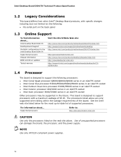
... listed below for the Intel Desktop Board DG41TX Supported processors Chipset information BIOS and driver updates Tested memory Visit this World Wide Web site: http://www.intel.com/products/motherboard/DG41TX/index.htm http://support.intel.com/support/motherboards/desktop http://www.intel.com/products/motherboard/DG41TX/index.htm http://processormatch.intel.com http://www.intel.com/products/desktop/chipsets...
... listed below for the Intel Desktop Board DG41TX Supported processors Chipset information BIOS and driver updates Tested memory Visit this World Wide Web site: http://www.intel.com/products/motherboard/DG41TX/index.htm http://support.intel.com/support/motherboards/desktop http://www.intel.com/products/motherboard/DG41TX/index.htm http://processormatch.intel.com http://www.intel.com/products/desktop/chipsets...

Product Specification
Page 15
If non-SPD memory is installed, the BIOS will attempt to Section 2.1.1 on page 39 for optimum performance. Table 3. Refer to correctly configure the memory settings, but performance and reliability may not function ... the DIMMs may be populated with DIMMs that support the Serial Presence Detect (SPD) data structure. This enables the BIOS to read the SPD data and program the chipset to : http://support.intel.com/support/motherboards/desktop/sb/ CS-025414.htm 15 Table 3 lists the supported DIMM configurations. Tested Memory Refer to...
If non-SPD memory is installed, the BIOS will attempt to Section 2.1.1 on page 39 for optimum performance. Table 3. Refer to correctly configure the memory settings, but performance and reliability may not function ... the DIMMs may be populated with DIMMs that support the Serial Presence Detect (SPD) data structure. This enables the BIOS to read the SPD data and program the chipset to : http://support.intel.com/support/motherboards/desktop/sb/ CS-025414.htm 15 Table 3 lists the supported DIMM configurations. Tested Memory Refer to...

Product Specification
Page 19
... The amount of system physical memory (as the operating system being used. An example of total system memory installed as well as set in the BIOS Setup program) for performing graphics functions. Once loaded, the operating system and graphics drivers allocate additional system memory to DVMT varies depending on the Extended...
... The amount of system physical memory (as the operating system being used. An example of total system memory installed as well as set in the BIOS Setup program) for performing graphics functions. Once loaded, the operating system and graphics drivers allocate additional system memory to DVMT varies depending on the Extended...
Product Specification
Page 22
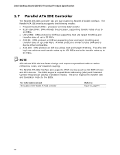
... interface also supports ATAPI devices (such as CD-ROM drives) and ATA devices. For information about The location of up to 66 MB/s. Intel Desktop Board DG41TX Technical Product Specification 1.7 Parallel ATA IDE Controller The Parallel ATA IDE controller has one bus-mastering Parallel ATA IDE interface. NOTE ATA-66 and...8226; ATA-100: DMA protocol on IDE bus supporting host and target throttling and transfer rates of the Parallel ATA IDE connector Refer to the BIOS. The ATA-100 logic can achieve read transfer rates up to 100 MB/s and write transfer rates up to 88 MB/s. The...
... interface also supports ATAPI devices (such as CD-ROM drives) and ATA devices. For information about The location of up to 66 MB/s. Intel Desktop Board DG41TX Technical Product Specification 1.7 Parallel ATA IDE Controller The Parallel ATA IDE controller has one bus-mastering Parallel ATA IDE interface. NOTE ATA-66 and...8226; ATA-100: DMA protocol on IDE bus supporting host and target throttling and transfer rates of the Parallel ATA IDE connector Refer to the BIOS. The ATA-100 logic can achieve read transfer rates up to 100 MB/s and write transfer rates up to 88 MB/s. The...

Product Specification
Page 23
.... The serial port supports data transfers at speeds up event interface • PCI power management support The BIOS Setup program provides configuration options for example, the date and time) might not be loaded into a wall socket, the battery has an estimated life... about The location of three years. The clock is located on the component side of the board. When the voltage drops below a certain level, the BIOS Setup program settings stored in , the standby current from the power supply extends the life of the battery. 1.9 Legacy I/O Controller The I /O controller. 1.9.1 Serial ...
.... The serial port supports data transfers at speeds up event interface • PCI power management support The BIOS Setup program provides configuration options for example, the date and time) might not be loaded into a wall socket, the battery has an estimated life... about The location of three years. The clock is located on the component side of the board. When the voltage drops below a certain level, the BIOS Setup program settings stored in , the standby current from the power supply extends the life of the battery. 1.9 Legacy I/O Controller The I /O controller. 1.9.1 Serial ...
Product Specification
Page 32
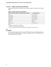
...; USB ports are turned off during S4/S5 states. • The PCI Express WAKE# signal is controlled by the enable/disable option in the BIOS. Intel Desktop Board DG41TX Technical Product Specification 1.13.1.2 Wake-up Devices and Events Table 8 lists the devices or specific events that provides full ACPI support. In addition, software...
...; USB ports are turned off during S4/S5 states. • The PCI Express WAKE# signal is controlled by the enable/disable option in the BIOS. Intel Desktop Board DG41TX Technical Product Specification 1.13.1.2 Wake-up Devices and Events Table 8 lists the devices or specific events that provides full ACPI support. In addition, software...

Product Specification
Page 33
.... Failure to do so can turn off ). The computer's response can be set using the Last Power State feature in before power was in the BIOS Setup program's Boot menu.
.... Failure to do so can turn off ). The computer's response can be set using the Last Power State feature in before power was in the BIOS Setup program's Boot menu.

Product Specification
Page 35
... on the PCI Express bus is asserted, the computer wakes from an ACPI S1, S3, S4, or S5 state (with Wake on PME enabled in BIOS). 1.13.2.7 WAKE# Signal Wake-up device or event, the system quickly returns to enter the ACPI S3 (Suspend-toRAM) sleep-state. The use of a USB... and events that can damage the power supply. The board supports the PCI Bus Power Management Interface Specification. Table 8 on enable/disable option in the BIOS enabled. 35 NOTE Wake from USB requires the use of providing adequate +5 V standby current.
... on the PCI Express bus is asserted, the computer wakes from an ACPI S1, S3, S4, or S5 state (with Wake on PME enabled in BIOS). 1.13.2.7 WAKE# Signal Wake-up device or event, the system quickly returns to enter the ACPI S3 (Suspend-toRAM) sleep-state. The use of a USB... and events that can damage the power supply. The board supports the PCI Bus Power Management Interface Specification. Table 8 on enable/disable option in the BIOS enabled. 35 NOTE Wake from USB requires the use of providing adequate +5 V standby current.

Product Specification
Page 39
These functions include the following: • BIOS/SPI Flash (16 Mbits) • Local APIC (19 MB) • Direct Media Interface (40 MB) • Front side bus interrupts (17 MB) • PCI Express ... possible to the operating system and applications, depending on the system configuration and operating system. 39 This could result in cards, PCI Express configuration space, BIOS (SPI Flash), and chipset overhead resides above the top of addressable system memory. Typically the address space that can reduce available addressable system memory. 2 Technical...
These functions include the following: • BIOS/SPI Flash (16 Mbits) • Local APIC (19 MB) • Direct Media Interface (40 MB) • Front side bus interrupts (17 MB) • PCI Express ... possible to the operating system and applications, depending on the system configuration and operating system. 39 This could result in cards, PCI Express configuration space, BIOS (SPI Flash), and chipset overhead resides above the top of addressable system memory. Typically the address space that can reduce available addressable system memory. 2 Technical...

Product Specification
Page 40
All installed system memory can be used will vary based on add-in cards and BIOS settings. Detailed System Memory Address Map 40 Figure 8 shows a schematic of system addresses. Figure 8. Intel Desktop Board DG41TX Technical Product Specification The amount of installed memory that can be used when there is no overlap of the system memory map.
All installed system memory can be used will vary based on add-in cards and BIOS settings. Detailed System Memory Address Map 40 Figure 8 shows a schematic of system addresses. Figure 8. Intel Desktop Board DG41TX Technical Product Specification The amount of installed memory that can be used when there is no overlap of the system memory map.

Product Specification
Page 41
... - 9FFFF 80000 - 9FBFF 00000 - 7FFFF Size 4095 MB 64 KB 64 KB 96 KB 160 KB 1 KB 127 KB 512 KB Description Extended memory Runtime BIOS Reserved Potential available high DOS memory (open to the PCI bus). FFFFFFFF 960 K - 1024 K F0000 - EFFFF C8000 - Video memory and...
... - 9FFFF 80000 - 9FBFF 00000 - 7FFFF Size 4095 MB 64 KB 64 KB 96 KB 160 KB 1 KB 127 KB 512 KB Description Extended memory Runtime BIOS Reserved Potential available high DOS memory (open to the PCI bus). FFFFFFFF 960 K - 1024 K F0000 - EFFFF C8000 - Video memory and...

Product Specification
Page 53
... the location of the Jumper Block 53 When the jumper is set to configure mode and the computer is powered-up, the BIOS compares the processor version and the microcode version in the BIOS and reports if the two match. Otherwise, the board could be damaged. Figure 13. The jumper determines the... BIOS Setup program's mode. Table 26 lists the jumper settings for the three modes: normal, configure, and recovery. Location of the jumper block. Always turn off ...
... the location of the Jumper Block 53 When the jumper is set to configure mode and the computer is powered-up, the BIOS compares the processor version and the microcode version in the BIOS and reports if the two match. Otherwise, the board could be damaged. Figure 13. The jumper determines the... BIOS Setup program's mode. Table 26 lists the jumper settings for the three modes: normal, configure, and recovery. Location of the jumper block. Always turn off ...

Product Specification
Page 54
See Section 3.7 for booting. Intel Desktop Board DG41TX Technical Product Specification Table 26. BIOS Setup Configuration Jumper Settings Function/Mode Jumper Setting Configuration Normal 1-2 The BIOS uses current configuration information and passwords for more information on BIOS recovery. 54 Configure 2-3 After the POST runs, Setup runs automatically. Recovery None The BIOS attempts to recover the BIOS configuration. The maintenance menu is displayed.
See Section 3.7 for booting. Intel Desktop Board DG41TX Technical Product Specification Table 26. BIOS Setup Configuration Jumper Settings Function/Mode Jumper Setting Configuration Normal 1-2 The BIOS uses current configuration information and passwords for more information on BIOS recovery. 54 Configure 2-3 After the POST runs, Setup runs automatically. Recovery None The BIOS attempts to recover the BIOS configuration. The maintenance menu is displayed.

Product Specification
Page 61
... 2.3 on page 53 shows how to put the board in configure mode. The BIOS displays a message during POST identifying the type of BIOS Features 3.1 Introduction The board uses an Intel BIOS that is stored in the BIOS and reports if the two match. The menu bar is accessed by pressing the ...configure mode. 61 The initial production BIOSs are identified as TXG4110H.86A. When the BIOS Setup configuration jumper is set to view and change the BIOS settings for the computer. The SPI Flash contains the BIOS Setup program, POST, the PCI auto-configuration utility, and Plug and Play support....
... 2.3 on page 53 shows how to put the board in configure mode. The BIOS displays a message during POST identifying the type of BIOS Features 3.1 Introduction The board uses an Intel BIOS that is stored in the BIOS and reports if the two match. The menu bar is accessed by pressing the ...configure mode. 61 The initial production BIOSs are identified as TXG4110H.86A. When the BIOS Setup configuration jumper is set to view and change the BIOS settings for the computer. The SPI Flash contains the BIOS Setup program, POST, the PCI auto-configuration utility, and Plug and Play support....


