Product Guide
Page 5
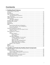
Contents 1 Desktop Board Features Desktop Board Components 11 Processor ...13 Main Memory...13 Intel® G35 Express Chipset 14 Intel G35 Graphics Subsystem 14 Audio Subsystem 15 Legacy Input/Output (I/O) Controller 16 LAN Subsystem 16 LAN Status Indicators 16 ...-up Support 23 ENERGY STAR* Qualified 23 Speaker...23 Battery ...23 Real-Time Clock 23 2 Installing and Replacing Desktop Board Components Before You Begin 25 Installation Precautions 26 Prevent Power Supply Overload 26 Observe Safety and Regulatory Requirements 26 Installing the I/O Shield 27 Installing and Removing the...
Contents 1 Desktop Board Features Desktop Board Components 11 Processor ...13 Main Memory...13 Intel® G35 Express Chipset 14 Intel G35 Graphics Subsystem 14 Audio Subsystem 15 Legacy Input/Output (I/O) Controller 16 LAN Subsystem 16 LAN Status Indicators 16 ...-up Support 23 ENERGY STAR* Qualified 23 Speaker...23 Battery ...23 Real-Time Clock 23 2 Installing and Replacing Desktop Board Components Before You Begin 25 Installation Precautions 26 Prevent Power Supply Overload 26 Observe Safety and Regulatory Requirements 26 Installing the I/O Shield 27 Installing and Removing the...

Product Guide
Page 6
Intel Desktop Board DG35EC Product Guide Installing a Processor Fan Heat Sink 32 Connecting the Processor Fan Heat Sink Cable 33 Removing the Processor 33 Installing and Removing Memory 34 ... Connectors 44 S/PDIF Connector 45 Front Panel Audio Header 45 IEEE 1394a Header 46 Serial Port Header 46 Front Panel Header 46 Alternate Front Panel Power LED Header 47 USB 2.0 Headers 47 Chassis Intrusion Header 48 Connecting to the Onboard Audio System 48 Connecting Chassis Fan and...
Intel Desktop Board DG35EC Product Guide Installing a Processor Fan Heat Sink 32 Connecting the Processor Fan Heat Sink Cable 33 Removing the Processor 33 Installing and Removing Memory 34 ... Connectors 44 S/PDIF Connector 45 Front Panel Audio Header 45 IEEE 1394a Header 46 Serial Port Header 46 Front Panel Header 46 Alternate Front Panel Power LED Header 47 USB 2.0 Headers 47 Chassis Intrusion Header 48 Connecting to the Onboard Audio System 48 Connecting Chassis Fan and...

Product Guide
Page 7
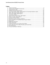
... Configuration with Two DIMMs 34 14. Installing a PCI Express x16 Card 39 19. Connecting the IDE Cable 42 22. Desktop Board DG35EC China RoHS Material Self Declaration Table 73 vii Remove the Protective Socket Cover 30 9. Use DDR2 DIMMs 36 17. Lift ... 75 Product Certifications 76 Board-Level Certification Markings 76 Chassis and Component Certifications 77 Figures 1. Removing a PCI Express x16 Card 40 20. Location of the BIOS Configuration Jumper Block 51 28. Location of the +5 V Standby Power Indicator 22 4. Desktop Board DG35EC Components 11 2. Connecting ...
... Configuration with Two DIMMs 34 14. Installing a PCI Express x16 Card 39 19. Connecting the IDE Cable 42 22. Desktop Board DG35EC China RoHS Material Self Declaration Table 73 vii Remove the Protective Socket Cover 30 9. Use DDR2 DIMMs 36 17. Lift ... 75 Product Certifications 76 Board-Level Certification Markings 76 Chassis and Component Certifications 77 Figures 1. Removing a PCI Express x16 Card 40 20. Location of the BIOS Configuration Jumper Block 51 28. Location of the +5 V Standby Power Indicator 22 4. Desktop Board DG35EC Components 11 2. Connecting ...
Product Guide
Page 8
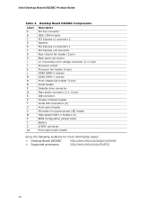
... Header Signal Names 46 8. Alternate Front Panel Power LED Header 47 10. Jumper Settings for Intel High Definition Audio 45 6. BIOS Error Messages 63 16. Product Certification Markings 76 viii Feature Summary 9 2. Front Panel Header 46 9. Intel Desktop Board DG35EC Product Guide Tables 1. Back Panel Audio Connector Definition 48 13. Desktop Board DG35EC Components 12 3. IEEE 1394a Signal Header...
... Header Signal Names 46 8. Alternate Front Panel Power LED Header 47 10. Jumper Settings for Intel High Definition Audio 45 6. BIOS Error Messages 63 16. Product Certification Markings 76 viii Feature Summary 9 2. Front Panel Header 46 9. Intel Desktop Board DG35EC Product Guide Tables 1. Back Panel Audio Connector Definition 48 13. Desktop Board DG35EC Components 12 3. IEEE 1394a Signal Header...

Product Guide
Page 10
...Intel Desktop Board DG35EC Product Guide Table 1. Feature Summary (continued) BIOS • Intel® Platform Innovation Framework for extensible firmware interface • 8 Mbit symmetrical flash memory device • Support for SMBIOS • Intel® Rapid BIOS Boot • Intel® Express BIOS Update Power Management • Support for Advanced Configuration and Power... For more information about Desktop Board DG35EC, including the Technical Product Specification (TPS), BIOS updates, and device drivers, go to http://support.intel.com/support/motherboards/desktop/. 10
...Intel Desktop Board DG35EC Product Guide Table 1. Feature Summary (continued) BIOS • Intel® Platform Innovation Framework for extensible firmware interface • 8 Mbit symmetrical flash memory device • Support for SMBIOS • Intel® Rapid BIOS Boot • Intel® Express BIOS Update Power Management • Support for Advanced Configuration and Power... For more information about Desktop Board DG35EC, including the Technical Product Specification (TPS), BIOS updates, and device drivers, go to http://support.intel.com/support/motherboards/desktop/. 10
Product Guide
Page 12
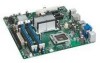
Intel Desktop Board DG35EC Product Guide Table 2. Desktop Board DG35EC Components Label A B C D E F G H I J K L M N O P Q R S T U V W X Y Z AA Description PCI bus connector IEEE 1394a header PCI Express x1 connector 2 Speaker PCI Express x1 connector... Alternate front panel power LED header High-speed USB 2.0 headers (2) BIOS configuration jumper block Battery S/PDIF connector Front panel audio header Go to the following locations for more information about: • Desktop Board DG35EC • Supported processors http://www.intel.com/design/motherbd http://www.intel.com/go/findCPU 12...
Intel Desktop Board DG35EC Product Guide Table 2. Desktop Board DG35EC Components Label A B C D E F G H I J K L M N O P Q R S T U V W X Y Z AA Description PCI bus connector IEEE 1394a header PCI Express x1 connector 2 Speaker PCI Express x1 connector... Alternate front panel power LED header High-speed USB 2.0 headers (2) BIOS configuration jumper block Battery S/PDIF connector Front panel audio header Go to the following locations for more information about: • Desktop Board DG35EC • Supported processors http://www.intel.com/design/motherbd http://www.intel.com/go/findCPU 12...
Product Guide
Page 13
Desktop Board DG35EC supports an Intel processor in Chapter 2 • Supported processors for more information about: • Instructions on the screen at power up. If your memory modules do not support SPD, you will attempt to configure the memory controller for : ... see a notification to the following locations for Desktop Board DG35EC, http://www.intel.com/go/findCPU Main Memory NOTE To be fully compliant with all applicable Intel ® SDRAM memory specifications, the board should be purchased separately. The Desktop Board supports the dual or single channel memory configurations ...
Desktop Board DG35EC supports an Intel processor in Chapter 2 • Supported processors for more information about: • Instructions on the screen at power up. If your memory modules do not support SPD, you will attempt to configure the memory controller for : ... see a notification to the following locations for Desktop Board DG35EC, http://www.intel.com/go/findCPU Main Memory NOTE To be fully compliant with all applicable Intel ® SDRAM memory specifications, the board should be purchased separately. The Desktop Board supports the dual or single channel memory configurations ...
Product Guide
Page 16
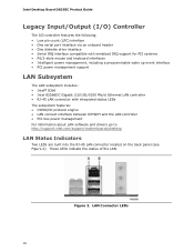
Figure 2. LAN Connector LEDs 16 These LEDs indicate the status of the LAN. Intel Desktop Board DG35EC Product Guide Legacy Input/Output (I/O) Controller The I/O controller features the following: • Low pin count (LPC) interface • One serial port interface .../CD protocol engine • LAN connect interface between ICH9DH and the LAN controller • PCI bus power management For information about LAN software and drivers go to http://support.intel.com/support/motherboards/desktop LAN Status Indicators Two LEDs are built into the RJ-45 LAN connector located on the back panel...
Figure 2. LAN Connector LEDs 16 These LEDs indicate the status of the LAN. Intel Desktop Board DG35EC Product Guide Legacy Input/Output (I/O) Controller The I/O controller features the following: • Low pin count (LPC) interface • One serial port interface .../CD protocol engine • LAN connect interface between ICH9DH and the LAN controller • PCI bus power management For information about LAN software and drivers go to http://support.intel.com/support/motherboards/desktop LAN Status Indicators Two LEDs are built into the RJ-45 LAN connector located on the back panel...
Product Guide
Page 17
... devices will function normally at USB 1.1 speeds. Desktop Board Features Table 3 describes the LED states when the board is powered up and the LAN subsystem is occurring 10 Mb/s data rate 100 Mb/s data rate 1000 Mb/s data rate Hi-Speed USB 2.0 Support The Desktop Board supports up to 10 USB 2.0 ports (six ... devices such as CD-ROM drives) • Older PIO Mode devices • Ultra DMA-33 and ATA-66/100 protocols Serial ATA The Desktop Board supports four Serial ATA channels (3.0 Gb/s) via ICH8. USB 2.0 support requires both an operating system and drivers that do not support USB 2.0....
... devices will function normally at USB 1.1 speeds. Desktop Board Features Table 3 describes the LED states when the board is powered up and the LAN subsystem is occurring 10 Mb/s data rate 100 Mb/s data rate 1000 Mb/s data rate Hi-Speed USB 2.0 Support The Desktop Board supports up to 10 USB 2.0 ports (six ... devices such as CD-ROM drives) • Older PIO Mode devices • Ultra DMA-33 and ATA-66/100 protocols Serial ATA The Desktop Board supports four Serial ATA channels (3.0 Gb/s) via ICH8. USB 2.0 support requires both an operating system and drivers that do not support USB 2.0....

Product Guide
Page 18
... pressing at the password prompt of Setup gives the user restricted access to view and change all Setup options. Intel Desktop Board DG35EC Product Guide Expandability For system expansion, the Desktop Board provides the following the instructions on whether the supervisor or user password was entered. 18 Serial ATA and IDE...• One PCI Express x16 connector • Two PCI Express x1 connectors • One PCI bus connector BIOS The BIOS provides the Power-On Self-Test (POST), the BIOS Setup program, the PCI/PCI Express and IDE auto-configuration utilities, and the video BIOS. The ...
... pressing at the password prompt of Setup gives the user restricted access to view and change all Setup options. Intel Desktop Board DG35EC Product Guide Expandability For system expansion, the Desktop Board provides the following the instructions on whether the supervisor or user password was entered. 18 Serial ATA and IDE...• One PCI Express x16 connector • Two PCI Express x1 connectors • One PCI bus connector BIOS The BIOS provides the Power-On Self-Test (POST), the BIOS Setup program, the PCI/PCI Express and IDE auto-configuration utilities, and the video BIOS. The ...
Product Guide
Page 19
...power supply voltages to detect levels above and below acceptable values • Fan speed controllers and sensors integrated into the legacy I/O controller • Thermal sensors in the processor, GMCH, and ICH8, plus an onboard remote sensor • Thermally monitored closed-loop fan control, for the location of Desktop Board DG35EC enable the board... to be connected to the chassis intrusion header on the Desktop Board. See Figure 23 for all onboard fans, that can adjust ...
...power supply voltages to detect levels above and below acceptable values • Fan speed controllers and sensors integrated into the legacy I/O controller • Thermal sensors in the processor, GMCH, and ICH8, plus an onboard remote sensor • Thermally monitored closed-loop fan control, for the location of Desktop Board DG35EC enable the board... to be connected to the chassis intrusion header on the Desktop Board. See Figure 23 for all onboard fans, that can adjust ...
Product Guide
Page 20
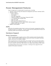
... receives the correct command, the power supply removes all non-standby voltages. Intel Desktop Board DG35EC Product Guide Power Management Features Power management is implemented at several levels, including: • Software support through system control. Hardware Support Power Connectors ATX12V-compliant power supplies can be set by using the Last Power State feature in before power was interrupted (either on page...
... receives the correct command, the power supply removes all non-standby voltages. Intel Desktop Board DG35EC Product Guide Power Management Features Power management is implemented at several levels, including: • Software support through system control. Hardware Support Power Connectors ATX12V-compliant power supplies can be set by using the Last Power State feature in before power was interrupted (either on page...
Product Guide
Page 21
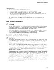
... wake events from the PCI and/or USB buses exceeds power supply capacity, the Desktop Board may lose register settings stored in power management and can be used with this specification can damage the power supply and/or effect ACPI S3 sleep state functionality. Add...needed. • All fan headers have a +12 V DC connection. The Desktop Board supports the PCI Bus Power Management Interface Specification. LAN wakeup capabilities enable remote wake-up signal that can damage the power supply. Instantly Available PC Technology CAUTIONS For Instantly Available PC technology, the 5 ...
... wake events from the PCI and/or USB buses exceeds power supply capacity, the Desktop Board may lose register settings stored in power management and can be used with this specification can damage the power supply and/or effect ACPI S3 sleep state functionality. Add...needed. • All fan headers have a +12 V DC connection. The Desktop Board supports the PCI Bus Power Management Interface Specification. LAN wakeup capabilities enable remote wake-up signal that can damage the power supply. Instantly Available PC Technology CAUTIONS For Instantly Available PC technology, the 5 ...
Product Guide
Page 22
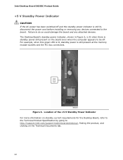
... installing or removing any attached devices. Intel Desktop Board DG35EC Product Guide +5 V Standby Power Indicator CAUTION If the AC power has been switched off . Failure to do so could damage the board and any devices connected to http://support.intel.com/support/motherboards/desktop/, finding the product, and clicking on standby current requirements for the Desktop Board, refer to the Technical Product...
... installing or removing any attached devices. Intel Desktop Board DG35EC Product Guide +5 V Standby Power Indicator CAUTION If the AC power has been switched off . Failure to do so could damage the board and any devices connected to http://support.intel.com/support/motherboards/desktop/, finding the product, and clicking on standby current requirements for the Desktop Board, refer to the Technical Product...
Product Guide
Page 23
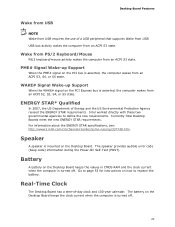
... of -day clock and 100-year calendar. The speaker provides audible error code (beep code) information during the Power-On Self-Test (POST). Currently Intel Desktop Boards meet the new ENERGY STAR requirements. Real-Time Clock The Desktop Board has a time-of Energy and the US Environmental Protection Agency revised the ENERGY STAR requirements. Speaker A speaker...
... of -day clock and 100-year calendar. The speaker provides audible error code (beep code) information during the Power-On Self-Test (POST). Currently Intel Desktop Boards meet the new ENERGY STAR requirements. Real-Time Clock The Desktop Board has a time-of Energy and the US Environmental Protection Agency revised the ENERGY STAR requirements. Speaker A speaker...
Product Guide
Page 25
...wrist strap and a conductive foam pad. Some circuitry on the board can continue to operate even though the front panel power button is not available, you how to: • Install the I/O shield • Install and remove the Desktop Board • Install and remove a processor • Install and...equipment. Disconnect the computer from its power source and from any telecommunications links, networks, or modems before you open the computer or perform any of the computer chassis. 25 If such a station is off. 2 Installing and Replacing Desktop Board Components This chapter tells you can...
...wrist strap and a conductive foam pad. Some circuitry on the board can continue to operate even though the front panel power button is not available, you how to: • Install the I/O shield • Install and remove the Desktop Board • Install and remove a processor • Install and...equipment. Disconnect the computer from its power source and from any telecommunications links, networks, or modems before you open the computer or perform any of the computer chassis. 25 If such a station is off. 2 Installing and Replacing Desktop Board Components This chapter tells you can...

Product Guide
Page 26
...Sharp pins on printed circuit assemblies • Rough edges and sharp corners on page 65. 26 Prevent Power Supply Overload Do not overload the power supply output. Observe Safety and Regulatory Requirements Read and adhere the instructions in the installation instructions. To...chassis and module suppliers, you increase safety risk and the possibility of the power supplies output circuits. Intel Desktop Board DG35EC Product Guide Installation Precautions When you install and test the Intel Desktop Board, observe all warnings and cautions in this section and the instructions supplied with...
...Sharp pins on printed circuit assemblies • Rough edges and sharp corners on page 65. 26 Prevent Power Supply Overload Do not overload the power supply output. Observe Safety and Regulatory Requirements Read and adhere the instructions in the installation instructions. To...chassis and module suppliers, you increase safety risk and the possibility of the power supplies output circuits. Intel Desktop Board DG35EC Product Guide Installation Precautions When you install and test the Intel Desktop Board, observe all warnings and cautions in this section and the instructions supplied with...
Product Guide
Page 28
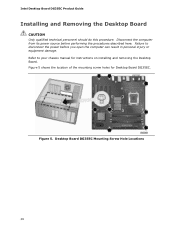
... the location of the mounting screw holes for instructions on installing and removing the Desktop Board. Refer to disconnect the power before performing the procedures described here. Figure 5. Failure to your chassis manual for Desktop Board DG35EC. Intel Desktop Board DG35EC Product Guide Installing and Removing the Desktop Board CAUTION Only qualified technical personnel should do this procedure. Disconnect the computer from...
... the location of the mounting screw holes for instructions on installing and removing the Desktop Board. Refer to disconnect the power before performing the procedures described here. Figure 5. Failure to your chassis manual for Desktop Board DG35EC. Intel Desktop Board DG35EC Product Guide Installing and Removing the Desktop Board CAUTION Only qualified technical personnel should do this procedure. Disconnect the computer from...

Product Guide
Page 29
... Begin" on page 22). Installing a Processor CAUTION Before installing or removing the processor, make sure the AC power has been removed by pushing the lever down and away from the computer; Installing and Replacing Desktop Board Components Installing and Removing a Processor Instructions on how to install the processor to do so could damage...
... Begin" on page 22). Installing a Processor CAUTION Before installing or removing the processor, make sure the AC power has been removed by pushing the lever down and away from the computer; Installing and Replacing Desktop Board Components Installing and Removing a Processor Instructions on how to install the processor to do so could damage...

Product Guide
Page 37
Make sure the clips at the bottom edge of the DIMM into place. Installing and Replacing Desktop Board Components To install a DIMM, follow these steps: 1. Figure 17. Turn off all peripheral devices connected to the open position. 5. When the DIMM is inserted, push ... keys in Figure 17). 7. Holding the DIMM by the edges, remove it from its anti-static package. 6. Turn off the computer and disconnect the AC power cord. 3. Make sure the clips are firmly in "Before You Begin" on the top edge of the DIMM socket(s) are pushed outward to the computer...
Make sure the clips at the bottom edge of the DIMM into place. Installing and Replacing Desktop Board Components To install a DIMM, follow these steps: 1. Figure 17. Turn off all peripheral devices connected to the open position. 5. When the DIMM is inserted, push ... keys in Figure 17). 7. Holding the DIMM by the edges, remove it from its anti-static package. 6. Turn off the computer and disconnect the AC power cord. 3. Make sure the clips are firmly in "Before You Begin" on the top edge of the DIMM socket(s) are pushed outward to the computer...

