Product Guide
Page 5
Contents 1 Desktop Board Features Desktop Board Components 11 Processor ...13 Main Memory...13 Intel® G35 Express Chipset 14 Intel G35 Graphics Subsystem 14 Audio Subsystem 15 Legacy Input/Output (I/O) Controller 16 LAN Subsystem 16 LAN Status Indicators 16 Hi-...Speed USB 2.0 Support 17 Enhanced IDE Interface 17 Serial ATA...17 Expandability...18 BIOS ...18 Serial ATA and IDE Auto Configuration...
Contents 1 Desktop Board Features Desktop Board Components 11 Processor ...13 Main Memory...13 Intel® G35 Express Chipset 14 Intel G35 Graphics Subsystem 14 Audio Subsystem 15 Legacy Input/Output (I/O) Controller 16 LAN Subsystem 16 LAN Status Indicators 16 Hi-...Speed USB 2.0 Support 17 Enhanced IDE Interface 17 Serial ATA...17 Expandability...18 BIOS ...18 Serial ATA and IDE Auto Configuration...

Product Guide
Page 6
Intel Desktop Board DG35EC Product Guide Installing a Processor Fan Heat Sink 32 Connecting the Processor Fan Heat Sink Cable 33 Removing the Processor 33 Installing and Removing Memory 34 Guidelines for Dual Channel Memory Configuration 34 Two or Four DIMMs 34 Three DIMMs 35 Installing DIMMs 36 Removing DIMMs 38 ...Power Supply Cables 49 Chassis Fan Cables 49 Power Supply Cables 50 Setting the BIOS Configuration Jumper 51 Clearing Passwords 52 3 Updating the BIOS Updating the BIOS with the Intel® Express BIOS Update Utility 59 Updating the BIOS with the ISO Image BIOS...
Intel Desktop Board DG35EC Product Guide Installing a Processor Fan Heat Sink 32 Connecting the Processor Fan Heat Sink Cable 33 Removing the Processor 33 Installing and Removing Memory 34 Guidelines for Dual Channel Memory Configuration 34 Two or Four DIMMs 34 Three DIMMs 35 Installing DIMMs 36 Removing DIMMs 38 ...Power Supply Cables 49 Chassis Fan Cables 49 Power Supply Cables 50 Setting the BIOS Configuration Jumper 51 Clearing Passwords 52 3 Updating the BIOS Updating the BIOS with the Intel® Express BIOS Update Utility 59 Updating the BIOS with the ISO Image BIOS...

Product Guide
Page 7
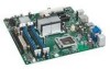
... Block 51 28. Removing the Battery 57 29. Desktop Board DG35EC Components 11 2. Desktop Board DG35EC Mounting Screw Hole Locations 28 6. Connecting the Processor Fan Heat Sink Cable to the Processor Fan Header ..........33 13. Dual Channel Memory Configuration with Three DIMMs 35 16. Installing a PCI Express x16 Card 39 19. Connecting the Diskette Drive Cable 41 21...
... Block 51 28. Removing the Battery 57 29. Desktop Board DG35EC Components 11 2. Desktop Board DG35EC Mounting Screw Hole Locations 28 6. Connecting the Processor Fan Heat Sink Cable to the Processor Fan Header ..........33 13. Dual Channel Memory Configuration with Three DIMMs 35 16. Installing a PCI Express x16 Card 39 19. Connecting the Diskette Drive Cable 41 21...

Product Guide
Page 10
Intel Desktop Board DG35EC Product Guide Table 1. Feature Summary (continued) BIOS • Intel® Platform Innovation Framework for extensible firmware interface • 8 Mbit symmetrical flash memory device • Support for SMBIOS • Intel® Rapid BIOS Boot • Intel® Express BIOS Update Power Management • Support for Advanced Configuration... XP Home For more information about Desktop Board DG35EC, including the Technical Product Specification (TPS), BIOS updates, and device drivers, go to http://support.intel.com/support/motherboards/desktop/. 10
Intel Desktop Board DG35EC Product Guide Table 1. Feature Summary (continued) BIOS • Intel® Platform Innovation Framework for extensible firmware interface • 8 Mbit symmetrical flash memory device • Support for SMBIOS • Intel® Rapid BIOS Boot • Intel® Express BIOS Update Power Management • Support for Advanced Configuration... XP Home For more information about Desktop Board DG35EC, including the Technical Product Specification (TPS), BIOS updates, and device drivers, go to http://support.intel.com/support/motherboards/desktop/. 10
Product Guide
Page 13
...; Up to 4.0 GB utilizing 512 Mb or 1 Gb technology • Up to configure the memory controller for Desktop Board DG35EC, http://www.intel.com/go/findCPU Main Memory NOTE To be fully compliant with all applicable Intel ® SDRAM memory specifications, the board should be purchased separately. Desktop Board Features Processor CAUTION Failure to use an appropriate power supply and/or not...
...; Up to 4.0 GB utilizing 512 Mb or 1 Gb technology • Up to configure the memory controller for Desktop Board DG35EC, http://www.intel.com/go/findCPU Main Memory NOTE To be fully compliant with all applicable Intel ® SDRAM memory specifications, the board should be purchased separately. Desktop Board Features Processor CAUTION Failure to use an appropriate power supply and/or not...
Product Guide
Page 21
...and/or USB buses exceeds power supply capacity, the Desktop Board may lose register settings stored in the S3 sleep state, the computer will appear to support the standard Instantly Available (ACPI S3 sleep state) configuration. While in memory. Power supplies used to enter the ACPI S3 (...Suspend-toRAM) sleep state. Instantly Available PC technology enables the board to wake the computer. 21 When signaled by the LED turning amber...
...and/or USB buses exceeds power supply capacity, the Desktop Board may lose register settings stored in the S3 sleep state, the computer will appear to support the standard Instantly Available (ACPI S3 sleep state) configuration. While in memory. Power supplies used to enter the ACPI S3 (...Suspend-toRAM) sleep state. Instantly Available PC technology enables the board to wake the computer. 21 When signaled by the LED turning amber...
Product Guide
Page 25
...and a conductive foam pad. 2 Installing and Replacing Desktop Board Components This chapter tells you how to: • Install the I/O shield • Install and remove the Desktop Board • Install and remove a processor • Install and remove memory • Install and remove a PCI Express x16 card... antistatic wrist strap and attaching it to record information about your computer, such as model, serial numbers, installed options, and configuration information. • Electrostatic discharge (ESD) can continue to operate even though the front panel power button is not available, you...
...and a conductive foam pad. 2 Installing and Replacing Desktop Board Components This chapter tells you how to: • Install the I/O shield • Install and remove the Desktop Board • Install and remove a processor • Install and remove memory • Install and remove a PCI Express x16 card... antistatic wrist strap and attaching it to record information about your computer, such as model, serial numbers, installed options, and configuration information. • Electrostatic discharge (ESD) can continue to operate even though the front panel power button is not available, you...
Product Guide
Page 34
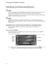
...configuration. Dual Channel Memory Configuration with all applicable Intel SDRAM memory specifications, the board requires DIMMs that support the Serial Presence Detect (SPD) data structure. Two or Four DIMMs Install a matched pair of channels A and B. Intel Desktop Board DG35EC Product Guide Installing and Removing Memory... NOTE To be populated. This is a requirement of the memory configuration used (dual or single channel), Channel A, DIMM 0 must ...
...configuration. Dual Channel Memory Configuration with all applicable Intel SDRAM memory specifications, the board requires DIMMs that support the Serial Presence Detect (SPD) data structure. Two or Four DIMMs Install a matched pair of channels A and B. Intel Desktop Board DG35EC Product Guide Installing and Removing Memory... NOTE To be populated. This is a requirement of the memory configuration used (dual or single channel), Channel A, DIMM 0 must ...

Product Guide
Page 35
... installed in channel A in single channel memory operation. 35 Dual Channel Memory Configuration with Three DIMMs NOTE All other memory configurations will result in either DIMM 0 or DIMM 1 of channel B (see Figure 14). Figure 15. Installing and Replacing Desktop Board Components If additional memory is to use three DIMMs in a dual-channel configuration, install a matched pair of DIMMs equal...
... installed in channel A in single channel memory operation. 35 Dual Channel Memory Configuration with Three DIMMs NOTE All other memory configurations will result in either DIMM 0 or DIMM 1 of channel B (see Figure 14). Figure 15. Installing and Replacing Desktop Board Components If additional memory is to use three DIMMs in a dual-channel configuration, install a matched pair of DIMMs equal...
Product Guide
Page 60
... BIOS update allows for the update of an Intel® Desktop Board BIOS to the latest production release regardless of these files through your computer supplier or by using either of the operating system installed on the Intel World Wide Web site at http://support.intel.com/support/motherboards/desktop. The Iflash BIOS update file is a standardized...
... BIOS update allows for the update of an Intel® Desktop Board BIOS to the latest production release regardless of these files through your computer supplier or by using either of the operating system installed on the Intel World Wide Web site at http://support.intel.com/support/motherboards/desktop. The Iflash BIOS update file is a standardized...
Product Guide
Page 63
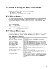
... the system date/time has not been set. The installed amount of memory in Channel A is not equal to the amount of memory in each channel. 63 Table 14. Maximum memory performance is required for reliable operation. BIOS Error Messages Error Message PROCESSOR_THERMAL_TRIP_ERROR ...messages. A Error Messages and Indicators Desktop Board DG35EC reports POST errors in two ways: • By sounding a beep code • By displaying an error message on reboot) BIOS Error Messages When a recoverable error occurs during POST if the video configuration fails (a faulty video card or ...
... the system date/time has not been set. The installed amount of memory in Channel A is not equal to the amount of memory in each channel. 63 Table 14. Maximum memory performance is required for reliable operation. BIOS Error Messages Error Message PROCESSOR_THERMAL_TRIP_ERROR ...messages. A Error Messages and Indicators Desktop Board DG35EC reports POST errors in two ways: • By sounding a beep code • By displaying an error message on reboot) BIOS Error Messages When a recoverable error occurs during POST if the video configuration fails (a faulty video card or ...

Product Specification
Page 5
... 1 Product Description 1.1 Overview 10 1.1.1 Feature Summary 10 1.1.2 Board Layout 12 1.1.3 Block Diagram 14 1.2 Legacy Considerations 15 1.3 Online Support 15 1.4 Processor 15 1.5 System Memory 16 1.5.1 Memory Configurations 17 1.6 Intel® G35 Express Chipset 19 1.6.1 Intel G35 Graphics Subsystem 19 1.6.2 USB 21 1.6.3 Serial ATA Interfaces 21...24 1.10.1 Audio Subsystem Software 25 1.10.2 Audio Connectors and Headers 25 1.11 LAN Subsystem 26 1.11.1 Intel® 82566DC Gigabit Ethernet Controller 26 1.11.2 LAN Subsystem Software 27 1.11.3 RJ-45 LAN Connector with Integrated ...
... 1 Product Description 1.1 Overview 10 1.1.1 Feature Summary 10 1.1.2 Board Layout 12 1.1.3 Block Diagram 14 1.2 Legacy Considerations 15 1.3 Online Support 15 1.4 Processor 15 1.5 System Memory 16 1.5.1 Memory Configurations 17 1.6 Intel® G35 Express Chipset 19 1.6.1 Intel G35 Graphics Subsystem 19 1.6.2 USB 21 1.6.3 Serial ATA Interfaces 21...24 1.10.1 Audio Subsystem Software 25 1.10.2 Audio Connectors and Headers 25 1.11 LAN Subsystem 26 1.11.1 Intel® 82566DC Gigabit Ethernet Controller 26 1.11.2 LAN Subsystem Software 27 1.11.3 RJ-45 LAN Connector with Integrated ...

Product Specification
Page 6
Intel Desktop Board DG35EC Technical Product Specification 2.4 Mechanical Considerations 51 2.4.1 Form Factor 51 2.5 Electrical Considerations 52 2.5.1 Power Supply Considerations 52 2.5.2 Fan Header Current Capability 53 2.5.3 Add-in Board Considerations 53 2.6 Thermal Considerations 53 2.7 Reliability 55 2.8 Environmental 56 3 Overview of BIOS Features 3.1 Introduction 57 3.2 BIOS Flash Memory Organization 58 3.3 Resource Configuration...POST 63 3.9 Adjusting Boot Speed 64 3.9.1 Peripheral Selection and Configuration 64 3.9.2 BIOS Boot Optimizations 64 3.10 BIOS Security Features...
Intel Desktop Board DG35EC Technical Product Specification 2.4 Mechanical Considerations 51 2.4.1 Form Factor 51 2.5 Electrical Considerations 52 2.5.1 Power Supply Considerations 52 2.5.2 Fan Header Current Capability 53 2.5.3 Add-in Board Considerations 53 2.6 Thermal Considerations 53 2.7 Reliability 55 2.8 Environmental 56 3 Overview of BIOS Features 3.1 Introduction 57 3.2 BIOS Flash Memory Organization 58 3.3 Resource Configuration...POST 63 3.9 Adjusting Boot Speed 64 3.9.1 Peripheral Selection and Configuration 64 3.9.2 BIOS Boot Optimizations 64 3.10 BIOS Security Features...
Product Specification
Page 7
... Header 44 14. Front Panel Audio Header 45 18. Major Board Components 12 2. Serial ATA Connectors 44 12. Back Panel Audio Connector Options 25 5. Detailed System Memory Address Map 38 9. States for Front Panel Header 47 12. Contents Figures 1. Memory Channel Configuration and DIMM Configuration 18 4. Connection Diagram for a Two-Color Power LED 48 24...
... Header 44 14. Front Panel Audio Header 45 18. Major Board Components 12 2. Serial ATA Connectors 44 12. Back Panel Audio Connector Options 25 5. Detailed System Memory Address Map 38 9. States for Front Panel Header 47 12. Contents Figures 1. Memory Channel Configuration and DIMM Configuration 18 4. Connection Diagram for a Two-Color Power LED 48 24...

Product Specification
Page 10
... in the SPI Flash device) • Support for Advanced Configuration and Power Interface (ACPI), Plug and Play, and SMBIOS • Support for PCI* Local Bus Specification Revision 2.3 • Support for up to 8 GB of system memory Intel® G35 Express Chipset, consisting of the Desktop Board DG35EC. Table 1. Intel Desktop Board DG35EC Technical Product Specification 1.1 Overview 1.1.1 Feature Summary Table 1 summarizes...
... in the SPI Flash device) • Support for Advanced Configuration and Power Interface (ACPI), Plug and Play, and SMBIOS • Support for PCI* Local Bus Specification Revision 2.3 • Support for up to 8 GB of system memory Intel® G35 Express Chipset, consisting of the Desktop Board DG35EC. Table 1. Intel Desktop Board DG35EC Technical Product Specification 1.1 Overview 1.1.1 Feature Summary Table 1 summarizes...
Product Specification
Page 15
... ... Intel Desktop Board DG35EC Desktop Board Support Available configurations for the most up-to-date list of supported processors. See the Intel web site listed below for the Desktop Board DG35EC Supported processors Chipset information BIOS and driver updates Tested Memory Visit this World Wide Web site: http://www.intel.com/products/motherboard/DG35EC/index.htm http://support.intel.com/support/motherboards/desktop http://www.intel.com/products/motherboard/DG35EC/index...
... ... Intel Desktop Board DG35EC Desktop Board Support Available configurations for the most up-to-date list of supported processors. See the Intel web site listed below for the Desktop Board DG35EC Supported processors Chipset information BIOS and driver updates Tested Memory Visit this World Wide Web site: http://www.intel.com/products/motherboard/DG35EC/index.htm http://support.intel.com/support/motherboards/desktop http://www.intel.com/products/motherboard/DG35EC/index...

Product Specification
Page 16
Intel Desktop Board DG35EC Technical Product Specification # INTEGRATOR'S NOTE Use only ATX12V-compliant power supplies. This enables the BIOS to read the SPD data and program the chipset to Section 2.2.2.4, page 46 1.5 System Memory The board has four DIMM sockets and supports the following memory... DIMM configurations. Tested Memory Refer to correctly configure the memory settings, but performance and reliability may not function under the determined frequency. If non-SPD memory is installed, the BIOS will attempt to : http://support.intel.com/support/motherboards/desktop/sb/...
Intel Desktop Board DG35EC Technical Product Specification # INTEGRATOR'S NOTE Use only ATX12V-compliant power supplies. This enables the BIOS to read the SPD data and program the chipset to Section 2.2.2.4, page 46 1.5 System Memory The board has four DIMM sockets and supports the following memory... DIMM configurations. Tested Memory Refer to correctly configure the memory settings, but performance and reliability may not function under the determined frequency. If non-SPD memory is installed, the BIOS will attempt to : http://support.intel.com/support/motherboards/desktop/sb/...

Product Specification
Page 17
... equal. For information about... Memory Configuration Examples Refer to dual channel operation; The bottommost DRAM memory (the memory that is nearest to the 8 GB address space limit), if any, is mapped to : http://www.intel.com/support/motherboards/desktop/sb/cs011965.htm 17 the topmost DRAM memory (the memory that is lowest within the system memory map) is mapped to...
... equal. For information about... Memory Configuration Examples Refer to dual channel operation; The bottommost DRAM memory (the memory that is nearest to the 8 GB address space limit), if any, is mapped to : http://www.intel.com/support/motherboards/desktop/sb/cs011965.htm 17 the topmost DRAM memory (the memory that is lowest within the system memory map) is mapped to...

Product Specification
Page 18
NOTE The DIMM 0 sockets of both channels are black. This is a requirement of Channel A must always be populated. Intel Desktop Board DG35EC Technical Product Specification Figure 3 illustrates the memory channel and DIMM configuration. Memory Channel Configuration and DIMM Configuration # INTEGRATOR'S NOTE Regardless of the memory configuration used (dual channel, single channel, or flex mode), DIMM 0 of the Intel Management Engine in ICH8. 18 The DIMM 1 sockets of both channels are blue. Figure 3.
NOTE The DIMM 0 sockets of both channels are black. This is a requirement of Channel A must always be populated. Intel Desktop Board DG35EC Technical Product Specification Figure 3 illustrates the memory channel and DIMM configuration. Memory Channel Configuration and DIMM Configuration # INTEGRATOR'S NOTE Regardless of the memory configuration used (dual channel, single channel, or flex mode), DIMM 0 of the Intel Management Engine in ICH8. 18 The DIMM 1 sockets of both channels are blue. Figure 3.

Product Specification
Page 58
...Security Clears passwords and displays processor information Displays processor and memory configuration Configures advanced features available through the chipset Sets passwords and security features Power Boot Configures power management features and power supply controls Selects boot options ...after adding a PCI card, the BIOS automatically configures interrupts, the I/O space, and other system resources. Table 31. Any interrupts set to Available in Setup are considered to configure the system. Intel Desktop Board DG35EC Technical Product Specification Table 30 lists the BIOS...
...Security Clears passwords and displays processor information Displays processor and memory configuration Configures advanced features available through the chipset Sets passwords and security features Power Boot Configures power management features and power supply controls Selects boot options ...after adding a PCI card, the BIOS automatically configures interrupts, the I/O space, and other system resources. Table 31. Any interrupts set to Available in Setup are considered to configure the system. Intel Desktop Board DG35EC Technical Product Specification Table 30 lists the BIOS...


