Product Guide
Page 5
Contents 1 Desktop Board Features Desktop Board Components 11 Processor ...13 Main Memory...13 Intel® G35 Express Chipset 14 Intel G35 Graphics Subsystem 14 Audio Subsystem 15 Legacy Input/Output (I/O) Controller 16 LAN Subsystem 16 LAN Status Indicators 16 Hi-Speed USB 2.0 ...# Signal Wake-up Support 23 ENERGY STAR* Qualified 23 Speaker...23 Battery ...23 Real-Time Clock 23 2 Installing and Replacing Desktop Board Components Before You Begin 25 Installation Precautions 26 Prevent Power Supply Overload 26 Observe Safety and Regulatory Requirements 26 Installing the I/O Shield...
Contents 1 Desktop Board Features Desktop Board Components 11 Processor ...13 Main Memory...13 Intel® G35 Express Chipset 14 Intel G35 Graphics Subsystem 14 Audio Subsystem 15 Legacy Input/Output (I/O) Controller 16 LAN Subsystem 16 LAN Status Indicators 16 Hi-Speed USB 2.0 ...# Signal Wake-up Support 23 ENERGY STAR* Qualified 23 Speaker...23 Battery ...23 Real-Time Clock 23 2 Installing and Replacing Desktop Board Components Before You Begin 25 Installation Precautions 26 Prevent Power Supply Overload 26 Observe Safety and Regulatory Requirements 26 Installing the I/O Shield...

Product Guide
Page 6
Intel Desktop Board DG35EC Product Guide Installing a Processor Fan Heat Sink 32 Connecting the Processor Fan Heat... Serial ATA (SATA) Cables 43 Connecting to the Internal Headers and Connectors 44 S/PDIF Connector 45 Front Panel Audio Header 45 IEEE 1394a Header 46 Serial Port Header 46 Front Panel Header 46 Alternate Front Panel Power LED Header... 47 USB 2.0 Headers 47 Chassis Intrusion Header 48 Connecting to the Onboard Audio System 48 Connecting Chassis Fan and Power Supply Cables 49 Chassis Fan Cables 49 Power Supply Cables 50 Setting ...
Intel Desktop Board DG35EC Product Guide Installing a Processor Fan Heat Sink 32 Connecting the Processor Fan Heat... Serial ATA (SATA) Cables 43 Connecting to the Internal Headers and Connectors 44 S/PDIF Connector 45 Front Panel Audio Header 45 IEEE 1394a Header 46 Serial Port Header 46 Front Panel Header 46 Alternate Front Panel Power LED Header... 47 USB 2.0 Headers 47 Chassis Intrusion Header 48 Connecting to the Onboard Audio System 48 Connecting Chassis Fan and Power Supply Cables 49 Chassis Fan Cables 49 Power Supply Cables 50 Setting ...

Product Guide
Page 7
... Memory Configuration with Two DIMMs 34 14. Back Panel Audio Connectors 48 25. Desktop Board DG35EC China RoHS Material Self Declaration Table 73 vii Desktop Board DG35EC Components 11 2. Connecting the Diskette Drive Cable 41 21. Internal Headers 44 24. Desktop Board DG35EC Mounting Screw Hole Locations 28 6. Close the Load Plate...71 China RoHS 72 EMC Regulations 74 Ensure Electromagnetic Compatibility (EMC) Compliance 75 Product Certifications 76 Board-Level Certification Markings 76 Chassis and Component Certifications 77 Figures 1. Installing a DIMM 37 18.
... Memory Configuration with Two DIMMs 34 14. Back Panel Audio Connectors 48 25. Desktop Board DG35EC China RoHS Material Self Declaration Table 73 vii Desktop Board DG35EC Components 11 2. Connecting the Diskette Drive Cable 41 21. Internal Headers 44 24. Desktop Board DG35EC Mounting Screw Hole Locations 28 6. Close the Load Plate...71 China RoHS 72 EMC Regulations 74 Ensure Electromagnetic Compatibility (EMC) Compliance 75 Product Certifications 76 Board-Level Certification Markings 76 Chassis and Component Certifications 77 Figures 1. Installing a DIMM 37 18.
Product Guide
Page 8
... Definition 48 13. China RoHS Environmentally Friendly Use Period Mark 72 19. Feature Summary 9 2. Front Panel Audio Header Signal Names for the BIOS Setup Program Modes 52 14. Alternate Front Panel Power LED Header 47 10.... Panel Header 46 9. Chassis Intrusion Header 48 12. Beep Codes 63 15. Safety Standards 65 17. Intel Desktop Board DG35EC Product Guide Tables 1. Lead-Free Second Level Interconnect Marks 71 18. EMC Regulations 74 20. Desktop Board DG35EC Components 12 3. BIOS Error Messages 63 16. Jumper Settings for Intel High Definition Audio 45 6.
... Definition 48 13. China RoHS Environmentally Friendly Use Period Mark 72 19. Feature Summary 9 2. Front Panel Audio Header Signal Names for the BIOS Setup Program Modes 52 14. Alternate Front Panel Power LED Header 47 10.... Panel Header 46 9. Chassis Intrusion Header 48 12. Beep Codes 63 15. Safety Standards 65 17. Intel Desktop Board DG35EC Product Guide Tables 1. Lead-Free Second Level Interconnect Marks 71 18. EMC Regulations 74 20. Desktop Board DG35EC Components 12 3. BIOS Error Messages 63 16. Jumper Settings for Intel High Definition Audio 45 6.
Product Guide
Page 9
... ― One port routed to the back panel ― One port routed to 8 GB of system memory Intel® G35 Express Chipset consisting of Intel® Desktop Board DG35EC. Table 1. Feature Summary Form Factor Processor Main Memory Chipset Graphics Audio Expansion Capabilities Legacy I/O Support Peripheral Interfaces microATX (243.84 millimeters [9.60 inches] x 243.84 millimeters [9.60...
... ― One port routed to the back panel ― One port routed to 8 GB of system memory Intel® G35 Express Chipset consisting of Intel® Desktop Board DG35EC. Table 1. Feature Summary Form Factor Processor Main Memory Chipset Graphics Audio Expansion Capabilities Legacy I/O Support Peripheral Interfaces microATX (243.84 millimeters [9.60 inches] x 243.84 millimeters [9.60...
Product Guide
Page 12
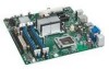
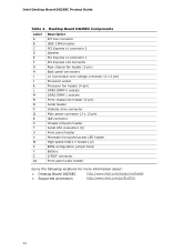
Desktop Board DG35EC Components Label A B C D E F G H I J K L M N O P Q R S T U V W X Y Z AA Description PCI bus connector IEEE 1394a header PCI Express x1 connector 2 Speaker PCI Express x1 connector 1 PCI ... front panel power LED header High-speed USB 2.0 headers (2) BIOS configuration jumper block Battery S/PDIF connector Front panel audio header Go to the following locations for more information about: • Desktop Board DG35EC • Supported processors http://www.intel.com/design/motherbd http://www.intel.com/go/findCPU 12 Intel Desktop Board DG35EC Product Guide Table 2.
Desktop Board DG35EC Components Label A B C D E F G H I J K L M N O P Q R S T U V W X Y Z AA Description PCI bus connector IEEE 1394a header PCI Express x1 connector 2 Speaker PCI Express x1 connector 1 PCI ... front panel power LED header High-speed USB 2.0 headers (2) BIOS configuration jumper block Battery S/PDIF connector Front panel audio header Go to the following locations for more information about: • Desktop Board DG35EC • Supported processors http://www.intel.com/design/motherbd http://www.intel.com/go/findCPU 12 Intel Desktop Board DG35EC Product Guide Table 2.

Product Guide
Page 15
...; Independent multi-streaming 5.1 audio (using the back panel audio connectors) and stereo (using the Intel High Definition front panel audio header) • All back panel audio connectors support automatic re-tasking Go to the following locations for more information about: • Audio drivers and utilities http://support.intel.com/support/motherboards/desktop/ • The front panel audio solution, page 45...
...; Independent multi-streaming 5.1 audio (using the back panel audio connectors) and stereo (using the Intel High Definition front panel audio header) • All back panel audio connectors support automatic re-tasking Go to the following locations for more information about: • Audio drivers and utilities http://support.intel.com/support/motherboards/desktop/ • The front panel audio solution, page 45...
Product Guide
Page 25
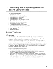
...Desktop Board • Install and remove a processor • Install and remove memory • Install and remove a PCI Express x16 card • Connect the diskette drive cable • Connect the IDE and Serial ATA cables • Connect to the internal headers • Connect to the onboard audio...compliance required for using an antistatic wrist strap and a conductive foam pad. If such a station is off. Some circuitry on the board can continue to record information about your computer, such as model, serial numbers, installed options, and configuration information. • Electrostatic...
...Desktop Board • Install and remove a processor • Install and remove memory • Install and remove a PCI Express x16 card • Connect the diskette drive cable • Connect the IDE and Serial ATA cables • Connect to the internal headers • Connect to the onboard audio...compliance required for using an antistatic wrist strap and a conductive foam pad. If such a station is off. Some circuitry on the board can continue to record information about your computer, such as model, serial numbers, installed options, and configuration information. • Electrostatic...

Product Guide
Page 44
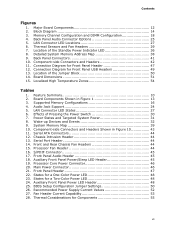
Intel Desktop Board DG35EC Product Guide Connecting to the Internal Headers and Connectors Before connecting cables to the internal headers and connectors, observe the precautions in "Before You Begin" on page 25. Internal Headers 44 Item Description A S/PDIF B Front panel audio C IEEE 1394a D Serial port Item Description E Front panel F Alternate front panel power LED G USB 2.0 H Chassis intrusion Figure 23. Figure 23 shows the location of the internal headers and connectors.
Intel Desktop Board DG35EC Product Guide Connecting to the Internal Headers and Connectors Before connecting cables to the internal headers and connectors, observe the precautions in "Before You Begin" on page 25. Internal Headers 44 Item Description A S/PDIF B Front panel audio C IEEE 1394a D Serial port Item Description E Front panel F Alternate front panel power LED G USB 2.0 H Chassis intrusion Figure 23. Figure 23 shows the location of the internal headers and connectors.
Product Guide
Page 45
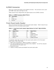
... shows the location of the S/PDIF connector. Turn off all peripheral devices connected to the front panel audio header, follow these steps: 1. Table 5 shows the pin assignments for Intel® High Definition Audio Pin Signal Name 1 PORT 1L 3 PORT 1R 5 PORT 2R 7 SENSE_SEND 9 PORT 2L Pin ...cable that connects the front panel audio solution to the computer. Observe the precautions in "Before You Begin" on page 25. 2. Installing and Replacing Desktop Board Components S/PDIF Connector Figure 23, A shows the location of the front panel audio header. Table 4 shows the pin...
... shows the location of the S/PDIF connector. Turn off all peripheral devices connected to the front panel audio header, follow these steps: 1. Table 5 shows the pin assignments for Intel® High Definition Audio Pin Signal Name 1 PORT 1L 3 PORT 1R 5 PORT 2R 7 SENSE_SEND 9 PORT 2L Pin ...cable that connects the front panel audio solution to the computer. Observe the precautions in "Before You Begin" on page 25. 2. Installing and Replacing Desktop Board Components S/PDIF Connector Figure 23, A shows the location of the front panel audio header. Table 4 shows the pin...

Product Guide
Page 48
... 2-Channel Function Line in Line out Mic in 4-Channel Function Left/right rear Left/right front Mic in the different audio modes. Figure 24 shows the back panel audio connectors. Table 11 shows the pin assignments for the chassis intrusion header. Table 11. Figure 24. This header can be...6-Channel Function Left/right rear Left/right front Subwoofer/center channel NOTE The back panel line out connector is removed. Intel Desktop Board DG35EC Product Guide Chassis Intrusion Header Figure 23, H on the chassis to detect if the chassis cover is designed to this output. 48
... 2-Channel Function Line in Line out Mic in 4-Channel Function Left/right rear Left/right front Mic in the different audio modes. Figure 24 shows the back panel audio connectors. Table 11 shows the pin assignments for the chassis intrusion header. Table 11. Figure 24. This header can be...6-Channel Function Left/right rear Left/right front Subwoofer/center channel NOTE The back panel line out connector is removed. Intel Desktop Board DG35EC Product Guide Chassis Intrusion Header Figure 23, H on the chassis to detect if the chassis cover is designed to this output. 48

Product Specification
Page 5
... 1.1 Overview 10 1.1.1 Feature Summary 10 1.1.2 Board Layout 12 1.1.3 Block Diagram 14 1.2 Legacy Considerations 15 1.3 Online Support 15 1.4 Processor 15 1.5 System Memory 16 1.5.1 Memory Configurations 17 1.6 Intel® G35 Express Chipset 19 1.6.1 Intel G35 Graphics Subsystem 19 1.6.2 USB 21 1.6.3 ...Drive Interface 23 1.9.3 PS/2 Keyboard and Mouse Interface 24 1.10 Audio Subsystem 24 1.10.1 Audio Subsystem Software 25 1.10.2 Audio Connectors and Headers 25 1.11 LAN Subsystem 26 1.11.1 Intel® 82566DC Gigabit Ethernet Controller 26 1.11.2 LAN Subsystem Software 27...
... 1.1 Overview 10 1.1.1 Feature Summary 10 1.1.2 Board Layout 12 1.1.3 Block Diagram 14 1.2 Legacy Considerations 15 1.3 Online Support 15 1.4 Processor 15 1.5 System Memory 16 1.5.1 Memory Configurations 17 1.6 Intel® G35 Express Chipset 19 1.6.1 Intel G35 Graphics Subsystem 19 1.6.2 USB 21 1.6.3 ...Drive Interface 23 1.9.3 PS/2 Keyboard and Mouse Interface 24 1.10 Audio Subsystem 24 1.10.1 Audio Subsystem Software 25 1.10.2 Audio Connectors and Headers 25 1.11 LAN Subsystem 26 1.11.1 Intel® 82566DC Gigabit Ethernet Controller 26 1.11.2 LAN Subsystem Software 27...
Product Specification
Page 7
...Settings 50 26. Recommended Power Supply Current Values 52 27. Thermal Considerations for Front Panel Header 47 12. Contents Figures 1. Board Dimensions 51 15. Front Panel Audio Header 45 18. States for a One-Color Power LED 48 23. Block Diagram 14 3. Serial Port Header 44 14.... Front Panel Header 47 22. Major Board Components 12 2. States for a Two-Color Power LED 48 24. Back Panel Audio Connector Options 25 5. Back Panel Connectors 41 10. Supported Memory Configurations 16 4. Connection Diagram for Front...
...Settings 50 26. Recommended Power Supply Current Values 52 27. Thermal Considerations for Front Panel Header 47 12. Contents Figures 1. Board Dimensions 51 15. Front Panel Audio Header 45 18. States for a One-Color Power LED 48 23. Block Diagram 14 3. Serial Port Header 44 14.... Front Panel Header 47 22. Major Board Components 12 2. States for a Two-Color Power LED 48 24. Back Panel Audio Connector Options 25 5. Back Panel Connectors 41 10. Supported Memory Configurations 16 4. Connection Diagram for Front...
Product Specification
Page 9
1 Product Description What This Chapter Contains 1.1 Overview 10 1.2 Legacy Considerations 15 1.3 Online Support 15 1.4 Processor 15 1.5 System Memory 16 1.6 Intel® G35 Express Chipset 19 1.7 Parallel IDE Controller 22 1.8 Real-Time Clock Subsystem 23 1.9 Legacy I/O Controller 23 1.10 Audio Subsystem 24 1.11 LAN Subsystem 26 1.12 Hardware Management Subsystem 28 1.13 Power Management 30 9
1 Product Description What This Chapter Contains 1.1 Overview 10 1.2 Legacy Considerations 15 1.3 Online Support 15 1.4 Processor 15 1.5 System Memory 16 1.6 Intel® G35 Express Chipset 19 1.7 Parallel IDE Controller 22 1.8 Real-Time Clock Subsystem 23 1.9 Legacy I/O Controller 23 1.10 Audio Subsystem 24 1.11 LAN Subsystem 26 1.12 Hardware Management Subsystem 28 1.13 Power Management 30 9

Product Specification
Page 10
...Intel Desktop Board DG35EC Technical Product Specification 1.1 Overview 1.1.1 Feature Summary Table 1 summarizes the major features of : • Intel® 82G35 Graphics and Memory Controller Hub (GMCH) • Intel® 82801HB I/O Controller Hub (ICH8) Intel® Graphics Media Accelerator (Intel® GMA) X3500 onboard graphics subsystem Audio 6-channel (5.1) audio subsystem using the Realtek* ALC888S audio...800 MHz DIMMs • Support for PCI Express* Revision 1.1 • Suspend to 8 GB of system memory Intel® G35 Express Chipset, consisting of the Desktop Board DG35EC.
...Intel Desktop Board DG35EC Technical Product Specification 1.1 Overview 1.1.1 Feature Summary Table 1 summarizes the major features of : • Intel® 82G35 Graphics and Memory Controller Hub (GMCH) • Intel® 82801HB I/O Controller Hub (ICH8) Intel® Graphics Media Accelerator (Intel® GMA) X3500 onboard graphics subsystem Audio 6-channel (5.1) audio subsystem using the Realtek* ALC888S audio...800 MHz DIMMs • Support for PCI Express* Revision 1.1 • Suspend to 8 GB of system memory Intel® G35 Express Chipset, consisting of the Desktop Board DG35EC.

Product Specification
Page 24
Intel Desktop Board DG35EC Technical Product Specification 1.9.3 PS/2 Keyboard and Mouse Interface The PS/2 keyboard and mouse connectors are located on the back panel. Audio Jack Support Audio Jack Supports Line in the bottom PS/2 connector and the mouse is connected or disconnected. Blue Yes Back panel - Table 4 lists the supported functions of ...
Intel Desktop Board DG35EC Technical Product Specification 1.9.3 PS/2 Keyboard and Mouse Interface The PS/2 keyboard and mouse connectors are located on the back panel. Audio Jack Support Audio Jack Supports Line in the bottom PS/2 connector and the mouse is connected or disconnected. Blue Yes Back panel - Table 4 lists the supported functions of ...

Product Specification
Page 25
... to Section 1.2, page 15 1.10.2 Audio Connectors and Headers The board contains audio connectors on the back panel and audio headers on the component side of the front panel audio header The back panel audio connectors Refer to power headphones or amplified speakers only. The available configurable audio ports are available from Intel's World Wide Web site. Back...
... to Section 1.2, page 15 1.10.2 Audio Connectors and Headers The board contains audio connectors on the back panel and audio headers on the component side of the front panel audio header The back panel audio connectors Refer to power headphones or amplified speakers only. The available configurable audio ports are available from Intel's World Wide Web site. Back...

Product Specification
Page 43
... header O Serial ATA connectors [4] P Front panel header Q Auxiliary front panel power LED header R Front panel USB header S Front panel USB header T S/PDIF connector U Front panel audio header 43
... header O Serial ATA connectors [4] P Front panel header Q Auxiliary front panel power LED header R Front panel USB header S Front panel USB header T S/PDIF connector U Front panel audio header 43

Product Specification
Page 45
...Pin Signal Name 1 HDR_BLNK_GRN 2 Not connected 3 HDR_BLNK_YEL In/Out Out Out Description Front panel green LED Front panel yellow LED 45 Front Panel Audio Header Pin Signal Name Pin 1 [Port 1] Left channel 2 3 [Port 1] Right channel 4 5 [Port 2] Right channel 6 7 SENSE_SEND...Signal Name Ground PRESENCE# (Dongle present) [Port 1] SENSE_RETURN Key (no pin) [Port 2] SENSE_RETURN 2.2.2.2 Add-in Card Connectors The board has the following considerations for the PCI Conventional bus connectors: • The PCI Conventional bus connector is connected to access sensor data on...
...Pin Signal Name 1 HDR_BLNK_GRN 2 Not connected 3 HDR_BLNK_YEL In/Out Out Out Description Front panel green LED Front panel yellow LED 45 Front Panel Audio Header Pin Signal Name Pin 1 [Port 1] Left channel 2 3 [Port 1] Right channel 4 5 [Port 2] Right channel 6 7 SENSE_SEND...Signal Name Ground PRESENCE# (Dongle present) [Port 1] SENSE_RETURN Key (no pin) [Port 2] SENSE_RETURN 2.2.2.2 Add-in Card Connectors The board has the following considerations for the PCI Conventional bus connectors: • The PCI Conventional bus connector is connected to access sensor data on...


