Product Guide
Page 5
Contents 1 Desktop Board Features Desktop Board Components 11 Processor ...13 Main Memory...13 Intel® G35 Express Chipset 14 Intel G35 Graphics Subsystem 14 Audio Subsystem 15 Legacy Input/Output (I/O) Controller 16 LAN Subsystem 16 LAN Status Indicators 16 Hi-Speed...23 WAKE# Signal Wake-up Support 23 ENERGY STAR* Qualified 23 Speaker...23 Battery ...23 Real-Time Clock 23 2 Installing and Replacing Desktop Board Components Before You Begin 25 Installation Precautions 26 Prevent Power Supply Overload 26 Observe Safety and Regulatory Requirements 26 Installing the I/O Shield 27...
Contents 1 Desktop Board Features Desktop Board Components 11 Processor ...13 Main Memory...13 Intel® G35 Express Chipset 14 Intel G35 Graphics Subsystem 14 Audio Subsystem 15 Legacy Input/Output (I/O) Controller 16 LAN Subsystem 16 LAN Status Indicators 16 Hi-Speed...23 WAKE# Signal Wake-up Support 23 ENERGY STAR* Qualified 23 Speaker...23 Battery ...23 Real-Time Clock 23 2 Installing and Replacing Desktop Board Components Before You Begin 25 Installation Precautions 26 Prevent Power Supply Overload 26 Observe Safety and Regulatory Requirements 26 Installing the I/O Shield 27...

Product Guide
Page 6
Intel Desktop Board DG35EC Product Guide Installing a Processor Fan Heat Sink 32 Connecting the Processor Fan Heat Sink Cable 33 Removing the Processor 33 Installing and Removing Memory 34 Guidelines for Dual Channel Memory Configuration 34 Two or Four DIMMs 34 Three DIMMs 35 Installing DIMMs 36 Removing DIMMs 38 Installing ...51 Clearing Passwords 52 3 Updating the BIOS Updating the BIOS with the Intel® Express BIOS Update Utility 59 Updating the BIOS with the ISO Image BIOS Update File or the Iflash Memory Update Utility 60 Obtaining the BIOS Update File 60 Updating the BIOS ...
Intel Desktop Board DG35EC Product Guide Installing a Processor Fan Heat Sink 32 Connecting the Processor Fan Heat Sink Cable 33 Removing the Processor 33 Installing and Removing Memory 34 Guidelines for Dual Channel Memory Configuration 34 Two or Four DIMMs 34 Three DIMMs 35 Installing DIMMs 36 Removing DIMMs 38 Installing ...51 Clearing Passwords 52 3 Updating the BIOS Updating the BIOS with the Intel® Express BIOS Update Utility 59 Updating the BIOS with the ISO Image BIOS Update File or the Iflash Memory Update Utility 60 Obtaining the BIOS Update File 60 Updating the BIOS ...

Product Guide
Page 7
... Plate 30 8. Removing a PCI Express x16 Card 40 20. Removing the Battery 57 29. Desktop Board DG35EC China RoHS Material Self Declaration Table 73 vii Connecting the IDE Cable 42 22. Install the Processor 31 11. Dual Channel Memory Configuration with Four DIMMs 35 15. Installing a DIMM 37 18. Location of the BIOS Configuration...
... Plate 30 8. Removing a PCI Express x16 Card 40 20. Removing the Battery 57 29. Desktop Board DG35EC China RoHS Material Self Declaration Table 73 vii Connecting the IDE Cable 42 22. Install the Processor 31 11. Dual Channel Memory Configuration with Four DIMMs 35 15. Installing a DIMM 37 18. Location of the BIOS Configuration...
Product Guide
Page 9
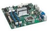
... IEEE 1394a ports ― One port routed to the back panel ― One port routed to 8 GB of system memory Intel® G35 Express Chipset consisting of Intel® Desktop Board DG35EC. Feature Summary Form Factor Processor Main Memory Chipset Graphics Audio Expansion Capabilities Legacy I/O Support Peripheral Interfaces microATX (243.84 millimeters [9.60 inches] x 243.84 millimeters...
... IEEE 1394a ports ― One port routed to the back panel ― One port routed to 8 GB of system memory Intel® G35 Express Chipset consisting of Intel® Desktop Board DG35EC. Feature Summary Form Factor Processor Main Memory Chipset Graphics Audio Expansion Capabilities Legacy I/O Support Peripheral Interfaces microATX (243.84 millimeters [9.60 inches] x 243.84 millimeters...

Product Guide
Page 10
Intel Desktop Board DG35EC Product Guide Table 1. Feature Summary (continued) BIOS • Intel® Platform Innovation Framework for extensible firmware interface • 8 Mbit symmetrical flash memory device • Support for SMBIOS • Intel® Rapid BIOS Boot • Intel® Express BIOS Update Power Management &#... x64 Edition • Microsoft Windows XP Home For more information about Desktop Board DG35EC, including the Technical Product Specification (TPS), BIOS updates, and device drivers, go to http://support.intel.com/support/motherboards/desktop/. 10
Intel Desktop Board DG35EC Product Guide Table 1. Feature Summary (continued) BIOS • Intel® Platform Innovation Framework for extensible firmware interface • 8 Mbit symmetrical flash memory device • Support for SMBIOS • Intel® Rapid BIOS Boot • Intel® Express BIOS Update Power Management &#... x64 Edition • Microsoft Windows XP Home For more information about Desktop Board DG35EC, including the Technical Product Specification (TPS), BIOS updates, and device drivers, go to http://support.intel.com/support/motherboards/desktop/. 10
Product Guide
Page 13
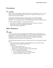
... Detect (SPD) data structure. The BIOS will see a notification to the following locations for Desktop Board DG35EC, http://www.intel.com/go/findCPU Main Memory NOTE To be fully compliant with all applicable Intel ® SDRAM memory specifications, the board should be purchased separately. Desktop Board Features Processor CAUTION Failure to use an appropriate power supply and/or not connecting...
... Detect (SPD) data structure. The BIOS will see a notification to the following locations for Desktop Board DG35EC, http://www.intel.com/go/findCPU Main Memory NOTE To be fully compliant with all applicable Intel ® SDRAM memory specifications, the board should be purchased separately. Desktop Board Features Processor CAUTION Failure to use an appropriate power supply and/or not connecting...
Product Guide
Page 14
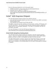
... x16 add-in card is installed on the Desktop Board back panel. Either the integrated Intel Graphics Media Accelerator X3500 (GMA X3500) graphics controller is a centralized controller for more information on the Intel G35 Express Chipset go to the processor, memory, PCI Express, and the DMI interconnect. Intel Desktop Board DG35EC Product Guide Go to the following devices: •...
... x16 add-in card is installed on the Desktop Board back panel. Either the integrated Intel Graphics Media Accelerator X3500 (GMA X3500) graphics controller is a centralized controller for more information on the Intel G35 Express Chipset go to the processor, memory, PCI Express, and the DMI interconnect. Intel Desktop Board DG35EC Product Guide Go to the following devices: •...

Product Guide
Page 15
... Technology (for more information go to http://www.intel.com/products/chipsets/clear_video/) ⎯ Support for playback of HD-DVD and Blu-ray Disc* technology DVDs ⎯ Software DVD at 30 fps full screen ⎯ Dynamic Video Memory Technology (DVMT) support up to 256 MB •...audio connectors support automatic re-tasking Go to the following locations for more information about: • Audio drivers and utilities http://support.intel.com/support/motherboards/desktop/ • The front panel audio solution, page 45 • The location and description the of back panel audio connectors, ...
... Technology (for more information go to http://www.intel.com/products/chipsets/clear_video/) ⎯ Support for playback of HD-DVD and Blu-ray Disc* technology DVDs ⎯ Software DVD at 30 fps full screen ⎯ Dynamic Video Memory Technology (DVMT) support up to 256 MB •...audio connectors support automatic re-tasking Go to the following locations for more information about: • Audio drivers and utilities http://support.intel.com/support/motherboards/desktop/ • The front panel audio solution, page 45 • The location and description the of back panel audio connectors, ...
Product Guide
Page 21
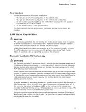
.... • The fans are off when the computer is indicated by a wake-up the computer. When signaled by the LED turning amber. Desktop Board Features Fan Headers The function/operation of the fans is as follows: • The fans are on or off . Failure to wake the ...in memory. Add-in cards that powers up device or event, the computer quickly returns to enter the ACPI S3 (Suspend-toRAM) sleep state. The LAN subsystem monitors network traffic and upon detecting a Magic Packet* frame, it asserts a wake-up of delivering adequate +5 V standby current. The Desktop Board supports...
.... • The fans are off when the computer is indicated by a wake-up the computer. When signaled by the LED turning amber. Desktop Board Features Fan Headers The function/operation of the fans is as follows: • The fans are on or off . Failure to wake the ...in memory. Add-in cards that powers up device or event, the computer quickly returns to enter the ACPI S3 (Suspend-toRAM) sleep state. The LAN subsystem monitors network traffic and upon detecting a Magic Packet* frame, it asserts a wake-up of delivering adequate +5 V standby current. The Desktop Board supports...
Product Guide
Page 22
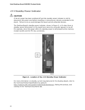
...of the +5 V Standby Power Indicator For more information on standby current requirements for the Desktop Board, refer to the Technical Product Specification by going to the board. The Desktop Board's standby power indicator, shown in Figure 3, is lit when there is standby power ...board and any devices connected to http://support.intel.com/support/motherboards/desktop/, finding the product, and clicking on the board even when the computer appears to be off and the standby power indicator is still present at the memory module sockets and the PCI bus connectors. Intel Desktop Board DG35EC...
...of the +5 V Standby Power Indicator For more information on standby current requirements for the Desktop Board, refer to the Technical Product Specification by going to the board. The Desktop Board's standby power indicator, shown in Figure 3, is lit when there is standby power ...board and any devices connected to http://support.intel.com/support/motherboards/desktop/, finding the product, and clicking on the board even when the computer appears to be off and the standby power indicator is still present at the memory module sockets and the PCI bus connectors. Intel Desktop Board DG35EC...
Product Guide
Page 25
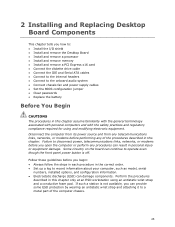
...the front panel power button is not available, you open the computer or perform any of the computer chassis. 25 2 Installing and Replacing Desktop Board Components This chapter tells you begin: • Always follow the steps in each procedure in the correct order. • Set up a...links, networks, or modems before you how to: • Install the I/O shield • Install and remove the Desktop Board • Install and remove a processor • Install and remove memory • Install and remove a PCI Express x16 card • Connect the diskette drive cable • Connect the IDE...
...the front panel power button is not available, you open the computer or perform any of the computer chassis. 25 2 Installing and Replacing Desktop Board Components This chapter tells you begin: • Always follow the steps in each procedure in the correct order. • Set up a...links, networks, or modems before you how to: • Install the I/O shield • Install and remove the Desktop Board • Install and remove a processor • Install and remove memory • Install and remove a PCI Express x16 card • Connect the diskette drive cable • Connect the IDE...
Product Guide
Page 34
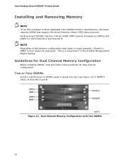
... speed and size (see Figure 13) in both Channel A and Channel B. Dual Channel Memory Configuration with all applicable Intel SDRAM memory specifications, the board requires DIMMs that support the Serial Presence Detect (SPD) data structure. Figure 13. Intel Desktop Board DG35EC Product Guide Installing and Removing Memory NOTE To be populated. NOTE Regardless of the ICH9DH Manageability Engine feature.
... speed and size (see Figure 13) in both Channel A and Channel B. Dual Channel Memory Configuration with all applicable Intel SDRAM memory specifications, the board requires DIMMs that support the Serial Presence Detect (SPD) data structure. Figure 13. Intel Desktop Board DG35EC Product Guide Installing and Removing Memory NOTE To be populated. NOTE Regardless of the ICH9DH Manageability Engine feature.

Product Guide
Page 35
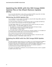
... and total size of the DIMMs installed in channel A in DIMM 0 (blue) and DIMM 1 (black) of channel B (see Figure 14). Installing and Replacing Desktop Board Components If additional memory is to use three DIMMs in a dual-channel configuration, install a matched pair of DIMMs equal in speed and size in either DIMM 0 or DIMM...
... and total size of the DIMMs installed in channel A in DIMM 0 (blue) and DIMM 1 (black) of channel B (see Figure 14). Installing and Replacing Desktop Board Components If additional memory is to use three DIMMs in a dual-channel configuration, install a matched pair of DIMMs equal in speed and size in either DIMM 0 or DIMM...

Product Guide
Page 53
Installing and Replacing Desktop Board Components 12. Replacing the Battery A coin-cell battery (CR2032) powers the real-time clock and CMOS memory. Batteries should be in the computer, and turn on the computer. To restore normal operation, place the jumper on page 57 shows the location of ...
Installing and Replacing Desktop Board Components 12. Replacing the Battery A coin-cell battery (CR2032) powers the real-time clock and CMOS memory. Batteries should be in the computer, and turn on the computer. To restore normal operation, place the jumper on page 57 shows the location of ...

Product Guide
Page 59
... your hard drive. (You can access the BIOS Setup program by either using the Intel Express BIOS Update utility or the Iflash Memory Update utility, and how to a removable USB device. Go to the DG35EC page, click "[view] Latest BIOS updates," and select the Express BIOS Update utility ... BIOS Update utility: 1. Navigate to the Intel World Wide Web site: http://support.intel.com/support/motherboards/desktop/ 2. Your system will be used to update the BIOS by pressing the key after the Power-On Self-Test (POST) memory test begins and before the operating system boot begins. This runs the...
... your hard drive. (You can access the BIOS Setup program by either using the Intel Express BIOS Update utility or the Iflash Memory Update utility, and how to a removable USB device. Go to the DG35EC page, click "[view] Latest BIOS updates," and select the Express BIOS Update utility ... BIOS Update utility: 1. Navigate to the Intel World Wide Web site: http://support.intel.com/support/motherboards/desktop/ 2. Your system will be used to update the BIOS by pressing the key after the Power-On Self-Test (POST) memory test begins and before the operating system boot begins. This runs the...
Product Guide
Page 60
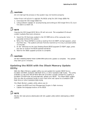
... BIOS file (including the Intel® Management Engine Firmware Image) • Intel® Integrator Toolkit Configuration File (optional) • Intel Flash Memory Update Utility You can obtain either the Iflash Memory Update Utility or the ISO...Intel Desktop Board DG35EC Product Guide Updating the BIOS with the ISO Image BIOS Update File The ISO Image BIOS update allows for the update of an Intel® Desktop Board BIOS to the latest production release regardless of the operating system installed on the Intel World Wide Web site at http://support.intel.com/support/motherboards/desktop...
... BIOS file (including the Intel® Management Engine Firmware Image) • Intel® Integrator Toolkit Configuration File (optional) • Intel Flash Memory Update Utility You can obtain either the Iflash Memory Update Utility or the ISO...Intel Desktop Board DG35EC Product Guide Updating the BIOS with the ISO Image BIOS Update File The ISO Image BIOS update allows for the update of an Intel® Desktop Board BIOS to the latest production release regardless of the operating system installed on the Intel World Wide Web site at http://support.intel.com/support/motherboards/desktop...
Product Guide
Page 61
...instructions to confirm the BIOS upgrade operation. 6. Download the ISO Image BIOS file. 2. Insert the CD that will not work. At the "Welcome to the Intel Desktop Board BIOS Upgrade CD-ROM" page, press any key to upgrade the BIOS using the ISO Image BIOS file: 1. Using software capable of the BIOS NOTE...can update the system BIOS from the hard drive if no key is complete. Wait for creating a bootable CD-ROM that was created in flash memory • Update the language section of uncompressing and writing an ISO image file to CD, burn the data to continue booting from CD-ROM" ...
...instructions to confirm the BIOS upgrade operation. 6. Download the ISO Image BIOS file. 2. Insert the CD that will not work. At the "Welcome to the Intel Desktop Board BIOS Upgrade CD-ROM" page, press any key to upgrade the BIOS using the ISO Image BIOS file: 1. Using software capable of the BIOS NOTE...can update the system BIOS from the hard drive if no key is complete. Wait for creating a bootable CD-ROM that was created in flash memory • Update the language section of uncompressing and writing an ISO image file to CD, burn the data to continue booting from CD-ROM" ...
Product Guide
Page 63
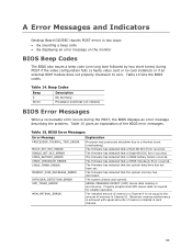
...POST, the BIOS displays an error message describing the problem. The firmware has detected that the system memory has decreased. A Error Messages and Indicators Desktop Board DG35EC reports POST errors in two ways: • By sounding a beep code • By displaying ...DETECT (SPD) device data missing or inconclusive. The firmware has detected that a CMOS battery failure occurred. Maximum memory performance is achieved with equal amounts of the BIOS error messages. BIOS Error Messages Error Message PROCESSOR_THERMAL_TRIP_ERROR MULTI_BIT_ECC_ERROR SINGLE_BIT_ECC_ERROR ...
...POST, the BIOS displays an error message describing the problem. The firmware has detected that the system memory has decreased. A Error Messages and Indicators Desktop Board DG35EC reports POST errors in two ways: • By sounding a beep code • By displaying ...DETECT (SPD) device data missing or inconclusive. The firmware has detected that a CMOS battery failure occurred. Maximum memory performance is achieved with equal amounts of the BIOS error messages. BIOS Error Messages Error Message PROCESSOR_THERMAL_TRIP_ERROR MULTI_BIT_ECC_ERROR SINGLE_BIT_ECC_ERROR ...

Product Specification
Page 5
... 1 Product Description 1.1 Overview 10 1.1.1 Feature Summary 10 1.1.2 Board Layout 12 1.1.3 Block Diagram 14 1.2 Legacy Considerations 15 1.3 Online Support 15 1.4 Processor 15 1.5 System Memory 16 1.5.1 Memory Configurations 17 1.6 Intel® G35 Express Chipset 19 1.6.1 Intel G35 Graphics Subsystem 19 1.6.2 USB 21 1.6.3 Serial ATA Interfaces ... 24 1.10.1 Audio Subsystem Software 25 1.10.2 Audio Connectors and Headers 25 1.11 LAN Subsystem 26 1.11.1 Intel® 82566DC Gigabit Ethernet Controller 26 1.11.2 LAN Subsystem Software 27 1.11.3 RJ-45 LAN Connector with Integrated ...
... 1 Product Description 1.1 Overview 10 1.1.1 Feature Summary 10 1.1.2 Board Layout 12 1.1.3 Block Diagram 14 1.2 Legacy Considerations 15 1.3 Online Support 15 1.4 Processor 15 1.5 System Memory 16 1.5.1 Memory Configurations 17 1.6 Intel® G35 Express Chipset 19 1.6.1 Intel G35 Graphics Subsystem 19 1.6.2 USB 21 1.6.3 Serial ATA Interfaces ... 24 1.10.1 Audio Subsystem Software 25 1.10.2 Audio Connectors and Headers 25 1.11 LAN Subsystem 26 1.11.1 Intel® 82566DC Gigabit Ethernet Controller 26 1.11.2 LAN Subsystem Software 27 1.11.3 RJ-45 LAN Connector with Integrated ...

Product Specification
Page 6
Intel Desktop Board DG35EC Technical Product Specification 2.4 Mechanical Considerations 51 2.4.1 Form Factor 51 2.5 Electrical Considerations 52 2.5.1 Power Supply Considerations 52 2.5.2 Fan Header Current Capability 53 2.5.3 Add-in Board Considerations 53 2.6 Thermal Considerations 53 2.7 Reliability 55 2.8 Environmental 56 3 Overview of BIOS Features 3.1 Introduction 57 3.2 BIOS Flash Memory ... of Conformity Statement 74 5.1.3 Product Ecology Statements 75 5.1.4 EMC Regulations 79 5.1.5 Product Certification Markings (Board Level 80 5.2 Battery Disposal Information 81 vi
Intel Desktop Board DG35EC Technical Product Specification 2.4 Mechanical Considerations 51 2.4.1 Form Factor 51 2.5 Electrical Considerations 52 2.5.1 Power Supply Considerations 52 2.5.2 Fan Header Current Capability 53 2.5.3 Add-in Board Considerations 53 2.6 Thermal Considerations 53 2.7 Reliability 55 2.8 Environmental 56 3 Overview of BIOS Features 3.1 Introduction 57 3.2 BIOS Flash Memory ... of Conformity Statement 74 5.1.3 Product Ecology Statements 75 5.1.4 EMC Regulations 79 5.1.5 Product Certification Markings (Board Level 80 5.2 Battery Disposal Information 81 vi


