
Product Guide
Page 6
Intel Desktop Board DG31PR Product Guide Installing and Removing a Processor 31 Installing a Processor 31 Installing the Processor Fan Heat Sink 34 Connecting the Processor Fan Heat Sink Cable 35 Removing the Processor 36 Installing and Removing Memory 36 Installing DIMMs 37 Removing DIMMs 39 Installing and Removing a PCI Express ... the BIOS Configuration Jumper 52 Clearing Passwords 53 Replacing the Battery 54 3 Updating the BIOS Updating the BIOS with the Intel® Express BIOS Update Utility 59 Updating the BIOS with the ISO Image BIOS Update File or the Iflash Memory Update...
Intel Desktop Board DG31PR Product Guide Installing and Removing a Processor 31 Installing a Processor 31 Installing the Processor Fan Heat Sink 34 Connecting the Processor Fan Heat Sink Cable 35 Removing the Processor 36 Installing and Removing Memory 36 Installing DIMMs 37 Removing DIMMs 39 Installing and Removing a PCI Express ... the BIOS Configuration Jumper 52 Clearing Passwords 53 Replacing the Battery 54 3 Updating the BIOS Updating the BIOS with the Intel® Express BIOS Update Utility 59 Updating the BIOS with the ISO Image BIOS Update File or the Iflash Memory Update...
Product Guide
Page 7
...I/O Shield 29 5. Install the Processor 33 11. Installing a DIMM 38 16. Removing a PCI Express x16 Card 41 18. Connecting a Serial ATA Cable 44 21. Feature Summary 9 2. Front Panel Intel High Definition Audio Header Signal Names...Processor Cover 33 10. Connecting the Processor Fan Heat Sink Cable to the Processor Fan Header ..........35 13. Back Panel Audio Connectors 49 23. LAN Connector LEDs 17 3. Lift the Socket Lever 31 7. Front Panel Header 48 10. Desktop Board DG31PR Components 11 2. Desktop Board DG31PR Components 12 3. Desktop Board DG31PR...
...I/O Shield 29 5. Install the Processor 33 11. Installing a DIMM 38 16. Removing a PCI Express x16 Card 41 18. Connecting a Serial ATA Cable 44 21. Feature Summary 9 2. Front Panel Intel High Definition Audio Header Signal Names...Processor Cover 33 10. Connecting the Processor Fan Heat Sink Cable to the Processor Fan Header ..........35 13. Back Panel Audio Connectors 49 23. LAN Connector LEDs 17 3. Lift the Socket Lever 31 7. Front Panel Header 48 10. Desktop Board DG31PR Components 11 2. Desktop Board DG31PR Components 12 3. Desktop Board DG31PR...
Product Guide
Page 9
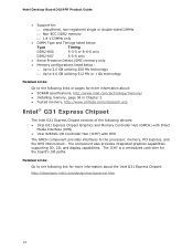
... Memory Chipset Graphics Audio LAN Support Expansion Capabilities Peripheral Interfaces microATX (218.44 millimeters [8.60 inches] x 243.84 millimeters [9.60 inches]) Support for an Intel® processor in the LGA775 package • Two 240-pin, DDR2 1.8 V (only) SDRAM Dual Inline Memory Module (DIMM) sockets • 800/667 MHz...8226; Up to 8 USB 2.0 ports ― Four ports routed to the back panel ― Four ports routed to 4 GB of system memory Intel® G31 Express Chipset consisting of Intel® Desktop Board DG31PR. Table 1 summarizes the major features of the Desktop Board.
... Memory Chipset Graphics Audio LAN Support Expansion Capabilities Peripheral Interfaces microATX (218.44 millimeters [8.60 inches] x 243.84 millimeters [9.60 inches]) Support for an Intel® processor in the LGA775 package • Two 240-pin, DDR2 1.8 V (only) SDRAM Dual Inline Memory Module (DIMM) sockets • 800/667 MHz...8226; Up to 8 USB 2.0 ports ― Four ports routed to the back panel ― Four ports routed to 4 GB of system memory Intel® G31 Express Chipset consisting of Intel® Desktop Board DG31PR. Table 1 summarizes the major features of the Desktop Board.
Product Guide
Page 13
... result in damage to this effect on installing or upgrading the processor, page 31 in the LGA775 package. Desktop Board DG31PR supports an Intel processor in Chapter 2 • Supported processors for Desktop Board DG31PR, http://www.intel.com/go /findCPU • Audio software and utilities http://www.intel.com/design/motherbd • LAN software and drivers http://www...
... result in damage to this effect on installing or upgrading the processor, page 31 in the LGA775 package. Desktop Board DG31PR supports an Intel processor in Chapter 2 • Supported processors for Desktop Board DG31PR, http://www.intel.com/go /findCPU • Audio software and utilities http://www.intel.com/design/motherbd • LAN software and drivers http://www...
Product Guide
Page 14
... (GMCH) with DMI The GMCH component provides interfaces to the following links or pages for more information about the Intel G31 Express Chipset: http://developer.intel.com/design/nav/pcserver.htm 14 Intel Desktop Board DG31PR Product Guide • Support for: ⎯ Unbuffered, non-registered single or double-sided DIMMs ⎯ Non-ECC DDR2... listed below: ⎯ Up to 2.0 GB utilizing 256 Mb technology ⎯ Up to 4.0 GB utilizing 512 Mb or 1 Gb technology Related Links: Go to the processor, memory, PCI Express, and the DMI interconnect.
... (GMCH) with DMI The GMCH component provides interfaces to the following links or pages for more information about the Intel G31 Express Chipset: http://developer.intel.com/design/nav/pcserver.htm 14 Intel Desktop Board DG31PR Product Guide • Support for: ⎯ Unbuffered, non-registered single or double-sided DIMMs ⎯ Non-ECC DDR2... listed below: ⎯ Up to 2.0 GB utilizing 256 Mb technology ⎯ Up to 4.0 GB utilizing 512 Mb or 1 Gb technology Related Links: Go to the processor, memory, PCI Express, and the DMI interconnect.
Product Guide
Page 18
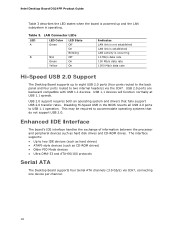
...one device per channel. 18 Table 3. USB 2.0 support requires both an operating system and drivers that do not support USB 2.0. Intel Desktop Board DG31PR Product Guide Table 3 describes the LED states when the board is operating. Enhanced IDE Interface The board's IDE interface handles the ...exchange of information between the processor and peripheral devices such as CD-ROM drives) • Older PIO Mode devices • ...
...one device per channel. 18 Table 3. USB 2.0 support requires both an operating system and drivers that do not support USB 2.0. Intel Desktop Board DG31PR Product Guide Table 3 describes the LED states when the board is operating. Enhanced IDE Interface The board's IDE interface handles the ...exchange of information between the processor and peripheral devices such as CD-ROM drives) • Older PIO Mode devices • ...
Product Guide
Page 22
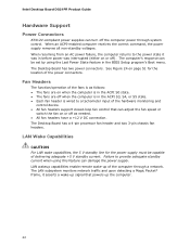
... follows: • The fans are on page 51 for the power supply must be set by using this feature can damage the power supply. Intel Desktop Board DG31PR Product Guide Hardware Support Power Connectors ATX12V-compliant power supplies can turn off when the computer is in the ACPI S3, S4, or S5... program's Boot menu. Fan Headers The function/operation of delivering adequate +5 V standby current. The Desktop Board has two power connectors. The Desktop Board has a 4-pin processor fan header and two 3-pin chassis fan headers.
... follows: • The fans are on page 51 for the power supply must be set by using this feature can damage the power supply. Intel Desktop Board DG31PR Product Guide Hardware Support Power Connectors ATX12V-compliant power supplies can turn off when the computer is in the ACPI S3, S4, or S5... program's Boot menu. Fan Headers The function/operation of delivering adequate +5 V standby current. The Desktop Board has two power connectors. The Desktop Board has a 4-pin processor fan header and two 3-pin chassis fan headers.
Product Guide
Page 28
Intel Desktop Board DG31PR Product Guide Installation Precautions When you install and test the Intel Desktop Board, observe all the modules within the computer is less than the output current rating of each of the power supplies output circuits. To ...; Sharp pins on connectors • Sharp pins on printed circuit assemblies • Rough edges and sharp corners on the chassis • Hot components (such as processors, voltage regulators, and heat sinks) • Damage to wires that could cause a short circuit Observe all warnings and cautions that the calculated total current loads...
Intel Desktop Board DG31PR Product Guide Installation Precautions When you install and test the Intel Desktop Board, observe all the modules within the computer is less than the output current rating of each of the power supplies output circuits. To ...; Sharp pins on connectors • Sharp pins on printed circuit assemblies • Rough edges and sharp corners on the chassis • Hot components (such as processors, voltage regulators, and heat sinks) • Damage to wires that could cause a short circuit Observe all warnings and cautions that the calculated total current loads...

Product Guide
Page 32
Lift the load plate (Figure 7, A). Lift the Load Plate 4. Do not discard the protective socket cover. Remove the plastic protective socket cover from the socket. Remove the Protective Socket Cover 32 Do not touch the socket contacts (Figure 7, B). Always replace the socket cover if the processor is removed from the load plate (Figure 8). Figure 8. Intel Desktop Board DG31PR Product Guide 3. Figure 7.
Lift the load plate (Figure 7, A). Lift the Load Plate 4. Do not discard the protective socket cover. Remove the plastic protective socket cover from the socket. Remove the Protective Socket Cover 32 Do not touch the socket contacts (Figure 7, B). Always replace the socket cover if the processor is removed from the load plate (Figure 8). Figure 8. Intel Desktop Board DG31PR Product Guide 3. Figure 7.

Product Guide
Page 34
Close the Load Plate Installing the Processor Fan Heat Sink Desktop Board DG31PR has mounting holes for a processor fan heat sink. Intel Desktop Board DG31PR Product Guide 7. Pressing down on how to attach the processor fan heat sink to the Desktop Board, refer to the boxed processor manual. 34 For instructions on the load plate (Figure 11, A), close and engage the socket lever (Figure 11, B). Figure 11.
Close the Load Plate Installing the Processor Fan Heat Sink Desktop Board DG31PR has mounting holes for a processor fan heat sink. Intel Desktop Board DG31PR Product Guide 7. Pressing down on how to attach the processor fan heat sink to the Desktop Board, refer to the boxed processor manual. 34 For instructions on the load plate (Figure 11, A), close and engage the socket lever (Figure 11, B). Figure 11.
Product Guide
Page 36
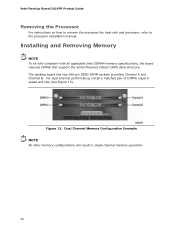
Figure 13. Installing and Removing Memory NOTE To be fully compliant with all applicable Intel SDRAM memory specifications, the board requires DIMMs that support the Serial Presence Detect (SPD) data structure. Dual Channel Memory Configuration ...performance, install a matched pair of DIMMs equal in single channel memory operation. 36 Intel Desktop Board DG31PR Product Guide Removing the Processor For instructions on how to remove the processor fan heat sink and processor, refer to the processor installation manual. The desktop board has two 240-pin DDR2 DIMM sockets providing Channel...
Figure 13. Installing and Removing Memory NOTE To be fully compliant with all applicable Intel SDRAM memory specifications, the board requires DIMMs that support the Serial Presence Detect (SPD) data structure. Dual Channel Memory Configuration ...performance, install a matched pair of DIMMs equal in single channel memory operation. 36 Intel Desktop Board DG31PR Product Guide Removing the Processor For instructions on how to remove the processor fan heat sink and processor, refer to the processor installation manual. The desktop board has two 240-pin DDR2 DIMM sockets providing Channel...

Product Guide
Page 63
...inconclusive. The firmware has detected that a CMOS battery failure occurred. Beep Codes Beep 3 Siren Description No memory Processor overheat (on the monitor BIOS Beep Codes The BIOS also issues a beep code (one long tone followed by ... CMOS_CHECKSUM_ERROR CMOS_TIMER_ERROR MEMORY_SIZE_DECREASE_ERROR INTRUDER_DETECTION_ERROR SPD_TOLER_ERROR MEM_OPTIMAL_ERROR Explanation Processor was opened. The installed amount of memory in Channel B. Table 12 lists the BIOS codes. A Error Messages and Indicators Desktop Board DG31PR reports POST errors in two ways: •...
...inconclusive. The firmware has detected that a CMOS battery failure occurred. Beep Codes Beep 3 Siren Description No memory Processor overheat (on the monitor BIOS Beep Codes The BIOS also issues a beep code (one long tone followed by ... CMOS_CHECKSUM_ERROR CMOS_TIMER_ERROR MEMORY_SIZE_DECREASE_ERROR INTRUDER_DETECTION_ERROR SPD_TOLER_ERROR MEM_OPTIMAL_ERROR Explanation Processor was opened. The installed amount of memory in Channel B. Table 12 lists the BIOS codes. A Error Messages and Indicators Desktop Board DG31PR reports POST errors in two ways: •...


