
Technical Product Specification
Page 2
... to the presented subject matter. Designers must not rely on request. Contact your local Intel sales office or your distributor to only the standard Intel® Next Unit of Computing Board with BIOS identifier GKPPT10H.86A. Copyright 2013, Intel Corporation. NO LICENSE, EXPRESS OR IMPLIED, BY ESTOPPEL OR OTHERWISE, TO ANY INTELLECTUAL PROPERTY...
... to the presented subject matter. Designers must not rely on request. Contact your local Intel sales office or your distributor to only the standard Intel® Next Unit of Computing Board with BIOS identifier GKPPT10H.86A. Copyright 2013, Intel Corporation. NO LICENSE, EXPRESS OR IMPLIED, BY ESTOPPEL OR OTHERWISE, TO ANY INTELLECTUAL PROPERTY...

Technical Product Specification
Page 3
...or Clarifications Date Type of Change Description of the following components: Device Intel Celeron 847 Intel BD82QS77 Stepping Q0 C1 S-Spec Numbers SR08N SLI8B Specification Changes or Clarifications ... Specification Changes or Specification Clarifications that apply to the Intel® Desktop Board DCP847SKE. Table 1. See http://developer.intel.com/products/desktop/motherboard/index.htm for the latest...power before setting or clearing the hard disk drive password. Board Identification Information Basic Intel® Next Unit of the board. 2. Errata Current characterized errata, if any...
...or Clarifications Date Type of Change Description of the following components: Device Intel Celeron 847 Intel BD82QS77 Stepping Q0 C1 S-Spec Numbers SR08N SLI8B Specification Changes or Clarifications ... Specification Changes or Specification Clarifications that apply to the Intel® Desktop Board DCP847SKE. Table 1. See http://developer.intel.com/products/desktop/motherboard/index.htm for the latest...power before setting or clearing the hard disk drive password. Board Identification Information Basic Intel® Next Unit of the board. 2. Errata Current characterized errata, if any...
Technical Product Specification
Page 5
... is intended to provide detailed, technical information about the conventions used on Intel Next Unit of Computing Board DCP847SKE A map of the resources of the Intel Next Unit of Computing Board The features supported by the BIOS Setup program A description of the BIOS error messages, beep codes, and POST codes Regulatory compliance and battery...
... is intended to provide detailed, technical information about the conventions used on Intel Next Unit of Computing Board DCP847SKE A map of the resources of the Intel Next Unit of Computing Board The features supported by the BIOS Setup program A description of the BIOS error messages, beep codes, and POST codes Regulatory compliance and battery...

Technical Product Specification
Page 8
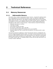
Intel Desktop Board DCP847SKE Technical Product Specification 2 Technical Reference 2.1 Memory Resources 35 2.1.1 Addressable Memory 35 2.1.2 Memory Map 37 2.2 Connectors and Headers 37 2.2.1 Back Panel Connectors 38 2.2.2 Connectors and Headers (Bottom 39 2.3 BIOS Setup Configuration Jumper 46 2.4 Mechanical Considerations 48 2.4.1 Form Factor 48 2.5 Electrical Considerations 49 2.5.1 Power Supply Considerations 49 2.5.2 Fan Header Current Capability...
Intel Desktop Board DCP847SKE Technical Product Specification 2 Technical Reference 2.1 Memory Resources 35 2.1.1 Addressable Memory 35 2.1.2 Memory Map 37 2.2 Connectors and Headers 37 2.2.1 Back Panel Connectors 38 2.2.2 Connectors and Headers (Bottom 39 2.3 BIOS Setup Configuration Jumper 46 2.4 Mechanical Considerations 48 2.4.1 Form Factor 48 2.5 Electrical Considerations 49 2.5.1 Power Supply Considerations 49 2.5.2 Fan Header Current Capability...
Technical Product Specification
Page 9
.... Board Dimensions 48 15. Components Shown in Figure 10 40 11. Supported Memory Configurations 19 5. Effects of the Standby Power LED 34 8. BIOS Setup Configuration Jumper Settings 47 17. Major Board Components (Bottom 15 3. Connection Diagram for a One-Color Power LED 44 16. Localized High ... 5. Components Shown in Figure 2 16 4. LAN Connector LED States 27 6. Wake-up Devices and Events 32 9. Thermal Considerations for BIOS Recovery 58 22. Tcontrol Values for Front Panel USB 2.0 Dual-Port Header 45 13. LAN Connector LED Locations 27 6. Location of the...
.... Board Dimensions 48 15. Components Shown in Figure 10 40 11. Supported Memory Configurations 19 5. Effects of the Standby Power LED 34 8. BIOS Setup Configuration Jumper Settings 47 17. Major Board Components (Bottom 15 3. Connection Diagram for a One-Color Power LED 44 16. Localized High ... 5. Components Shown in Figure 2 16 4. LAN Connector LED States 27 6. Wake-up Devices and Events 32 9. Thermal Considerations for BIOS Recovery 58 22. Tcontrol Values for Front Panel USB 2.0 Dual-Port Header 45 13. LAN Connector LED Locations 27 6. Location of the...

Technical Product Specification
Page 10
Port 80h POST Code Ranges 64 28. EMC Regulations 75 32. BIOS Error Messages 63 27. Regulatory Compliance Marks 79 x Front-panel Power LED Blink Codes 63 26. Typical Port 80h POST Sequence 69 30. Master Key and User Hard Drive Password Functions 60 24. Intel Desktop Board DCP847SKE Technical Product Specification 23. Supervisor and User Password Functions 61 25. Safety Standards 71 31. Port 80h POST Codes 65 29.
Port 80h POST Code Ranges 64 28. EMC Regulations 75 32. BIOS Error Messages 63 27. Regulatory Compliance Marks 79 x Front-panel Power LED Blink Codes 63 26. Typical Port 80h POST Sequence 69 30. Master Key and User Hard Drive Password Functions 60 24. Intel Desktop Board DCP847SKE Technical Product Specification 23. Supervisor and User Password Functions 61 25. Safety Standards 71 31. Port 80h POST Codes 65 29.

Technical Product Specification
Page 11
...) continued 11 Table 2. Feature Summary Form Factor Processor Memory Chipset Graphics Audio Peripheral Interfaces Expansion Capabilities BIOS 4.0 inches by 4.0 inches (101.60 millimeters by 101.60 millimeters) • Soldered-down Intel® Celeron® processor 847 with up to 17 W TDP ― Integrated graphics ― Integrated ... for SSD support • One PCI Express Half-Mini Card connector • One PCI Express Full-Mini Card connector • Intel® BIOS resident in the Serial Peripheral Interface (SPI) Flash device • Support for 1.35 V low voltage JEDEC memory...
...) continued 11 Table 2. Feature Summary Form Factor Processor Memory Chipset Graphics Audio Peripheral Interfaces Expansion Capabilities BIOS 4.0 inches by 4.0 inches (101.60 millimeters by 101.60 millimeters) • Soldered-down Intel® Celeron® processor 847 with up to 17 W TDP ― Integrated graphics ― Integrated ... for SSD support • One PCI Express Half-Mini Card connector • One PCI Express Full-Mini Card connector • Intel® BIOS resident in the Serial Peripheral Interface (SPI) Flash device • Support for 1.35 V low voltage JEDEC memory...

Technical Product Specification
Page 18
... World Wide Web site: http://www.intel.com/products/motherboard/index.htm http://www.intel.com/p/en_US/support?iid=hdr+support http://ark.intel.com Chipset information BIOS and driver updates Tested memory Integration information http://www.intel.com/products/desktop/chipsets/index.htm http://downloadcenter.intel.com http://www.intel.com/support/motherboards/desktop/sb/CS025414...
... World Wide Web site: http://www.intel.com/products/motherboard/index.htm http://www.intel.com/p/en_US/support?iid=hdr+support http://ark.intel.com Chipset information BIOS and driver updates Tested memory Integration information http://www.intel.com/products/desktop/chipsets/index.htm http://downloadcenter.intel.com http://www.intel.com/support/motherboards/desktop/sb/CS025414...

Technical Product Specification
Page 19
... GB maximum total system memory (with SO-DIMMs that support the Serial Presence Detect (SPD) data structure. Table 5. If non-SPD memory is installed, the BIOS will attempt to correctly configure the memory settings, but performance and reliability may not function under the determined frequency. Table 5 lists the supported SO-DIMM... all applicable DDR SDRAM memory specifications, the board should be impacted or the SO-DIMMs may be populated with 4 Gb memory technology). This allows the BIOS to read the SPD data and program the chipset to change. 19
... GB maximum total system memory (with SO-DIMMs that support the Serial Presence Detect (SPD) data structure. Table 5. If non-SPD memory is installed, the BIOS will attempt to correctly configure the memory settings, but performance and reliability may not function under the determined frequency. Table 5 lists the supported SO-DIMM... all applicable DDR SDRAM memory specifications, the board should be impacted or the SO-DIMMs may be populated with 4 Gb memory technology). This allows the BIOS to read the SPD data and program the chipset to change. 19

Technical Product Specification
Page 24
... attached to device connections. In Native mode, standard PCI Conventional bus resource steering is transparent to the latest available by Intel. 24 For information about installing drivers during installation. The underlying SATA functionality is used for host to the cable. See...Half-Mini Card • One port is as follows: • Three front panel ports (via the Intel QS77 Express Chipset. The SATA controller can operate in the BIOS. Intel Desktop Board DCP847SKE Technical Product Specification 1.6.2 USB The board supports seven USB 2.0 ports. A point-to Figure...
... attached to device connections. In Native mode, standard PCI Conventional bus resource steering is transparent to the latest available by Intel. 24 For information about installing drivers during installation. The underlying SATA functionality is used for host to the cable. See...Half-Mini Card • One port is as follows: • Three front panel ports (via the Intel QS77 Express Chipset. The SATA controller can operate in the BIOS. Intel Desktop Board DCP847SKE Technical Product Specification 1.6.2 USB The board supports seven USB 2.0 ports. A point-to Figure...

Technical Product Specification
Page 25
...13 shows the location of the battery. 1.9 LAN Subsystem The LAN subsystem consists of the following: • Intel 82579V Gigabit Ethernet Controller (10/100/1000 Mb/s) • Intel QS77 Express Chipset • RJ-45 LAN connector with integrated status LEDs Additional features of the battery. When ...the voltage drops below a certain level, the BIOS Setup program settings stored in , the standby current from ...
...13 shows the location of the battery. 1.9 LAN Subsystem The LAN subsystem consists of the following: • Intel 82579V Gigabit Ethernet Controller (10/100/1000 Mb/s) • Intel QS77 Express Chipset • RJ-45 LAN connector with integrated status LEDs Additional features of the battery. When ...the voltage drops below a certain level, the BIOS Setup program settings stored in , the standby current from ...
Technical Product Specification
Page 33
... that can be off (the power supply is off, and the front panel LED is set in the BIOS, the computer will appear to be set using the Last Power State feature in the BIOS Setup program's Boot menu. The use of a USB peripheral that powers up of the computer through a network...
... that can be off (the power supply is off, and the front panel LED is set in the BIOS, the computer will appear to be set using the Last Power State feature in the BIOS Setup program's Boot menu. The use of a USB peripheral that powers up of the computer through a network...
Technical Product Specification
Page 35
.... Typically the address space that is allocated for PCI Express add-in cards, PCI Express configuration space, BIOS (SPI Flash device), and chipset overhead resides above the 4 GB boundary. These functions include the following: • BIOS/SPI Flash device (16 Mbit) • Local APIC (19 MB) • Direct Media Interface (40 MB...
.... Typically the address space that is allocated for PCI Express add-in cards, PCI Express configuration space, BIOS (SPI Flash device), and chipset overhead resides above the 4 GB boundary. These functions include the following: • BIOS/SPI Flash device (16 Mbit) • Local APIC (19 MB) • Direct Media Interface (40 MB...
Technical Product Specification
Page 37
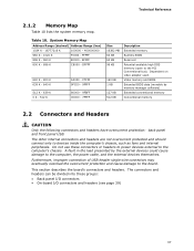
... 9FBFF 00000 - 7FFFF Size 16382 MB 64 KB 64 KB 96 KB 160 KB 1 KB 127 KB 512 KB Description Extended memory Runtime BIOS Reserved Potential available high DOS memory (open to the board. The connectors and headers can be divided into these connectors or headers to power ...devices external to the computer's chassis. Video memory and BIOS Extended BIOS data (movable by the external devices could cause damage to devices inside the computer's chassis, such as fans and internal peripherals. Furthermore,...
... 9FBFF 00000 - 7FFFF Size 16382 MB 64 KB 64 KB 96 KB 160 KB 1 KB 127 KB 512 KB Description Extended memory Runtime BIOS Reserved Potential available high DOS memory (open to the board. The connectors and headers can be divided into these connectors or headers to power ...devices external to the computer's chassis. Video memory and BIOS Extended BIOS data (movable by the external devices could cause damage to devices inside the computer's chassis, such as fans and internal peripherals. Furthermore,...

Technical Product Specification
Page 44
...Switch Header Pins 5 and 7 can be connected to an LED to provide a visual indicator that is normally open. or two-color LED. Intel Desktop Board DCP847SKE Technical Product Specification Figure 11. States for Front Panel Header 2.2.2.4.1 Hard Drive Activity LED Header Pins 1 and 3 can be set... via BIOS setup. 44 When the switch is closed, the board resets and runs the POST. 2.2.2.4.3 Power/Sleep LED Header Pins 2 and 4 can ...
...Switch Header Pins 5 and 7 can be connected to an LED to provide a visual indicator that is normally open. or two-color LED. Intel Desktop Board DCP847SKE Technical Product Specification Figure 11. States for Front Panel Header 2.2.2.4.1 Hard Drive Activity LED Header Pins 1 and 3 can be set... via BIOS setup. 44 When the switch is closed, the board resets and runs the POST. 2.2.2.4.3 Power/Sleep LED Header Pins 2 and 4 can ...

Technical Product Specification
Page 46
... configure mode and the computer is powered-up, the BIOS compares the processor version and the microcode version in the BIOS and reports if the two match. Figure 13. Intel Desktop Board DCP847SKE Technical Product Specification 2.3 BIOS Setup Configuration Jumper CAUTION Do not move a jumper with... the power on. Figure 13 shows the location of the BIOS Configuration Setup Jumper 46 ...
... configure mode and the computer is powered-up, the BIOS compares the processor version and the microcode version in the BIOS and reports if the two match. Figure 13. Intel Desktop Board DCP847SKE Technical Product Specification 2.3 BIOS Setup Configuration Jumper CAUTION Do not move a jumper with... the power on. Figure 13 shows the location of the BIOS Configuration Setup Jumper 46 ...
Technical Product Specification
Page 47
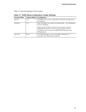
... settings for booting. Table 17. Press F9 (restore defaults) while in Configure mode to restore the BIOS/CMOS settings to recover the BIOS configuration. BIOS Setup Configuration Jumper Settings Function/Mode Normal Configure Jumper Setting 1-2 2-3 Configuration The BIOS uses current configuration information and passwords for the jumper. Note that this Configure mode is the...
... settings for booting. Table 17. Press F9 (restore defaults) while in Configure mode to restore the BIOS/CMOS settings to recover the BIOS configuration. BIOS Setup Configuration Jumper Settings Function/Mode Normal Configure Jumper Setting 1-2 2-3 Configuration The BIOS uses current configuration information and passwords for the jumper. Note that this Configure mode is the...

Technical Product Specification
Page 52
... Tcontrol Values for the components that the temperature measurement in the components and does not directly correspond to Case Temperature. Intel Desktop Board DCP847SKE Technical Product Specification Table 19 provides maximum case temperatures for Components Component Tcontrol Processor For processor case temperature...thermal sensor is dissipating less than TDP, the case temperature should be dissipated by embedded thermal sensors in the system BIOS is maintained at the geometric center of the component corresponds to the Maximum Case Temperature. It is important to note...
... Tcontrol Values for the components that the temperature measurement in the components and does not directly correspond to Case Temperature. Intel Desktop Board DCP847SKE Technical Product Specification Table 19 provides maximum case temperatures for Components Component Tcontrol Processor For processor case temperature...thermal sensor is dissipating less than TDP, the case temperature should be dissipated by embedded thermal sensors in the system BIOS is maintained at the geometric center of the component corresponds to the Maximum Case Temperature. It is important to note...
Technical Product Specification
Page 55
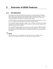
... begins and before the operating system boot begins. The BIOS Setup program is in the BIOS and reports if the two match. The BIOS displays a message during POST identifying the type of BIOS Features 3.1 Introduction The board uses a Intel Visual BIOS that is powered-up, the BIOS compares the CPU version and the microcode version in configure...
... begins and before the operating system boot begins. The BIOS Setup program is in the BIOS and reports if the two match. The BIOS displays a message during POST identifying the type of BIOS Features 3.1 Introduction The board uses a Intel Visual BIOS that is powered-up, the BIOS compares the CPU version and the microcode version in configure...

Technical Product Specification
Page 56
.... Using this information. When you to configure the operating system. (Keyboards and mice are not yet available. Intel Desktop Board DCP847SKE Technical Product Specification 3.2 BIOS Flash Memory Organization The Serial Peripheral Interface Flash Memory (SPI Flash) includes a 64 Mb (8192 KB) flash... as event detection and error logging Non-Plug and Play operating systems require an additional interface for managing computers in the BIOS Setup program.) 56 Legacy USB support is the Management Information Format (MIF) database, which contains information about the computing ...
.... Using this information. When you to configure the operating system. (Keyboards and mice are not yet available. Intel Desktop Board DCP847SKE Technical Product Specification 3.2 BIOS Flash Memory Organization The Serial Peripheral Interface Flash Memory (SPI Flash) includes a 64 Mb (8192 KB) flash... as event detection and error logging Non-Plug and Play operating systems require an additional interface for managing computers in the BIOS Setup program.) 56 Legacy USB support is the Management Information Format (MIF) database, which contains information about the computing ...


