
Technical Product Specification
Page 8
...Headers (Bottom 44 2.3 BIOS Setup Configuration Jumper 52 2.4 Intel® Management Engine BIOS Extension (Intel® MEBX) Reset Header . 53 2.5 Mechanical Considerations 55 2.5.1 Form Factor 55 2.6 Electrical Considerations 56 2.6.1 Power Supply Considerations 56 2.6.2 Fan Header Current Capability 57 2.7 Thermal Considerations...Disk Drive Password Security Feature 66 3.9 BIOS Security Features 67 4 Error Messages and Blink Codes 4.1 Front-panel Power LED Blink Codes 69 4.2 BIOS Error Messages 69 5 Regulatory Compliance and Battery Disposal Information 5.1 Regulatory Compliance ...
...Headers (Bottom 44 2.3 BIOS Setup Configuration Jumper 52 2.4 Intel® Management Engine BIOS Extension (Intel® MEBX) Reset Header . 53 2.5 Mechanical Considerations 55 2.5.1 Form Factor 55 2.6 Electrical Considerations 56 2.6.1 Power Supply Considerations 56 2.6.2 Fan Header Current Capability 57 2.7 Thermal Considerations...Disk Drive Password Security Feature 66 3.9 BIOS Security Features 67 4 Error Messages and Blink Codes 4.1 Front-panel Power LED Blink Codes 69 4.2 BIOS Error Messages 69 5 Regulatory Compliance and Battery Disposal Information 5.1 Regulatory Compliance ...

Technical Product Specification
Page 9
...for Front Panel Header 50 11. Connection Diagram for Components 59 21. Dual-Port Front Panel USB 2.0 Header 48 13. 19 V Internal Power Supply Connector 49 14. Tcontrol Values for Front Panel USB 2.0 Dual-Port Header 51 12. Supported Memory Configurations 19 5. Connectors and Headers Shown... in Figure 10 45 11. Front Panel Header 49 15. Intel MEBX Reset Header Signals 54 18. Master Key and User Hard Drive Password Functions 66 25. Fan Header Current Capability 57 19. ...
...for Front Panel Header 50 11. Connection Diagram for Components 59 21. Dual-Port Front Panel USB 2.0 Header 48 13. 19 V Internal Power Supply Connector 49 14. Tcontrol Values for Front Panel USB 2.0 Dual-Port Header 51 12. Supported Memory Configurations 19 5. Connectors and Headers Shown... in Figure 10 45 11. Front Panel Header 49 15. Intel MEBX Reset Header Signals 54 18. Master Key and User Hard Drive Password Functions 66 25. Fan Header Current Capability 57 19. ...

Technical Product Specification
Page 12
... power supply voltages • Thermal sense to detect out of range thermal values • One processor fan header • Fan sense input used to monitor fan activity • Simple fan speed control • Intel® Active Management Technology (Intel® AMT) 8.0 • Intel® Virtualization (Intel® VT) • Intel® Virtualization for Directed I/O (Intel® VT-d) • Intel...
... power supply voltages • Thermal sense to detect out of range thermal values • One processor fan header • Fan sense input used to monitor fan activity • Simple fan speed control • Intel® Active Management Technology (Intel® AMT) 8.0 • Intel® Virtualization (Intel® VT) • Intel® Virtualization for Directed I/O (Intel® VT-d) • Intel...
Technical Product Specification
Page 18
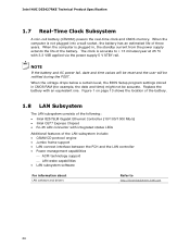
... D53427RKE NUC Board Support Available configurations for providing power to Section 2.5.1 on page 56 for information on power supply requirements for this World Wide Web site: http://www.intel.com/products/motherboard/index.htm http://www.intel.com/p/en_US/support?iid=hdr+support http://ark.intel.com Chipset information BIOS and driver updates Tested memory Integration...
... D53427RKE NUC Board Support Available configurations for providing power to Section 2.5.1 on page 56 for information on power supply requirements for this World Wide Web site: http://www.intel.com/products/motherboard/index.htm http://www.intel.com/p/en_US/support?iid=hdr+support http://ark.intel.com Chipset information BIOS and driver updates Tested memory Integration...
Technical Product Specification
Page 26
...during the POST. When the voltage drops below a certain level, the BIOS Setup program settings stored in , the standby current from the power supply extends the life of the LAN subsystem include: • CSMA/CD protocol engine • Jumbo frame support • LAN connect interface ...ºC with 3.3 VSB applied via the power supply 5 V STBY rail. Figure 1 on page 13 shows the location of the battery. 1.8 LAN Subsystem The LAN subsystem consists of the following: • Intel 82579LM Gigabit Ethernet Controller (10/100/1000 Mb/s) • Intel QS77 Express Chipset • RJ-45 LAN...
...during the POST. When the voltage drops below a certain level, the BIOS Setup program settings stored in , the standby current from the power supply extends the life of the LAN subsystem include: • CSMA/CD protocol engine • Jumbo frame support • LAN connect interface ...ºC with 3.3 VSB applied via the power supply 5 V STBY rail. Figure 1 on page 13 shows the location of the battery. 1.8 LAN Subsystem The LAN subsystem consists of the following: • Intel 82579LM Gigabit Ethernet Controller (10/100/1000 Mb/s) • Intel QS77 Express Chipset • RJ-45 LAN...
Technical Product Specification
Page 32
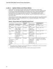
... wake-up devices used can be turned off . Intel NUC D53427RKE Technical Product Specification 1.10.1.1 System States and Power States Under ACPI, the operating system directs all system and device power state transitions. Table 8 lists the power states supported by the system chassis' power supply. 2. The operating system puts devices in the system. 32 Context saved...
... wake-up devices used can be turned off . Intel NUC D53427RKE Technical Product Specification 1.10.1.1 System States and Power States Under ACPI, the operating system directs all system and device power state transitions. Table 8 lists the power states supported by the system chassis' power supply. 2. The operating system puts devices in the system. 32 Context saved...
Technical Product Specification
Page 34
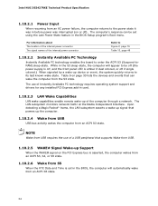
...network. The computer's response can wake the computer from the S3 state. Intel NUC D53427RKE Technical Product Specification 1.10.2.1 Power Input When resuming from an AC power failure, the computer returns to enter the ACPI S3 (Suspend-toRAM) ... WAKE# Signal Wake-up device or event, the system quickly returns to be set using the Last Power State feature in the BIOS, the computer will appear to its last known wake state. The LAN subsystem... LAN subsystem asserts a wake-up signal that can be off (the power supply is off, and the front panel LED is amber if dual colored, or off ).
...network. The computer's response can wake the computer from the S3 state. Intel NUC D53427RKE Technical Product Specification 1.10.2.1 Power Input When resuming from an AC power failure, the computer returns to enter the ACPI S3 (Suspend-toRAM) ... WAKE# Signal Wake-up device or event, the system quickly returns to be set using the Last Power State feature in the BIOS, the computer will appear to its last known wake state. The LAN subsystem... LAN subsystem asserts a wake-up signal that can be off (the power supply is off, and the front panel LED is amber if dual colored, or off ).

Technical Product Specification
Page 49
... a Molex 5566-2 header which accepts a Molex 5557-02R connector from the power supply. The internal 1 x 2 power connector is GND. Figure 11 is 10 A. • Internal Power Supply - the board can alternatively be powered through a 19 V DC connector on the back panel. Table 13. 19 V Internal Power Supply Connector Pin Signal Name 1 Ground 2 +19 V (±10%) For information about...
... a Molex 5566-2 header which accepts a Molex 5557-02R connector from the power supply. The internal 1 x 2 power connector is GND. Figure 11 is 10 A. • Internal Power Supply - the board can alternatively be powered through a 19 V DC connector on the back panel. Table 13. 19 V Internal Power Supply Connector Pin Signal Name 1 Ground 2 +19 V (±10%) For information about...
Technical Product Specification
Page 51
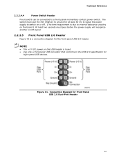
... on or off. (The time requirement is due to internal debounce circuitry on the board.) At least two seconds must pass before the power supply will recognize another on the USB header is a connection diagram for Front Panel USB 2.0 Dual-Port Header 51 Connection Diagram for the front... panel USB 2.0 header. Figure 11. NOTE • The +5 V DC power on /off signal. 2.2.2.5 Front Panel USB 2.0 Header Figure 12 is fused. • Use only a front panel USB connector that conforms to a front panel...
... on or off. (The time requirement is due to internal debounce circuitry on the board.) At least two seconds must pass before the power supply will recognize another on the USB header is a connection diagram for Front Panel USB 2.0 Dual-Port Header 51 Connection Diagram for the front... panel USB 2.0 header. Figure 11. NOTE • The +5 V DC power on /off signal. 2.2.2.5 Front Panel USB 2.0 Header Figure 12 is fused. • Use only a front panel USB connector that conforms to a front panel...

Technical Product Specification
Page 53
... defaults. NOTE After using the MEBX Reset, a "CMOS battery failure" warning will accomplish the following: • Return all Intel ME parameters to their default values. Momentarily shorting pins 1 and 2 with a jumper (not supplied) will occur during the next POST. Table 16. Note that this Configure mode is displayed. A recovery CD or flash... the BIOS configuration. This is expected and does not indicate a component failure. 53 After the POST runs, Setup runs automatically. CAUTION Always turn off the power and unplug the power cord from the computer before reapplying...
... defaults. NOTE After using the MEBX Reset, a "CMOS battery failure" warning will accomplish the following: • Return all Intel ME parameters to their default values. Momentarily shorting pins 1 and 2 with a jumper (not supplied) will occur during the next POST. Table 16. Note that this Configure mode is displayed. A recovery CD or flash... the BIOS configuration. This is expected and does not indicate a component failure. 53 After the POST runs, Setup runs automatically. CAUTION Always turn off the power and unplug the power cord from the computer before reapplying...
Technical Product Specification
Page 56
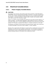
... no isolation circuitry between the external 19 V DC jack and the internal 1 x 2 power connector. Intel NUC D53427RKE Technical Product Specification 2.6 Electrical Considerations 2.6.1 Power Supply Considerations CAUTION The external 19 V DC jack is the primary power input connector of both external and internal power supply units could result in custom-developed systems that can be attached to the...
... no isolation circuitry between the external 19 V DC jack and the internal 1 x 2 power connector. Intel NUC D53427RKE Technical Product Specification 2.6 Electrical Considerations 2.6.1 Power Supply Considerations CAUTION The external 19 V DC jack is the primary power input connector of both external and internal power supply units could result in custom-developed systems that can be attached to the...
Technical Product Specification
Page 76
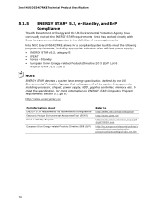
...US Department of the system's components, including processor, chipset, power supply, HDD, graphics controller, memory, etc. Intel NUC Board D53427RKE allows for a compliant system built to meet the specification. Intel has worked directly with these two governmental agencies in the definition... European Union Energy-related Products Directive 2009 (ErP) Refer to meet the following program requirements, including appropriate selection of an efficient power supply: • ENERGY STAR v5.2, category B • EPEAT* • Korea e-Standby • European Union Energy-related Products...
...US Department of the system's components, including processor, chipset, power supply, HDD, graphics controller, memory, etc. Intel NUC Board D53427RKE allows for a compliant system built to meet the specification. Intel has worked directly with these two governmental agencies in the definition... European Union Energy-related Products Directive 2009 (ErP) Refer to meet the following program requirements, including appropriate selection of an efficient power supply: • ENERGY STAR v5.2, category B • EPEAT* • Korea e-Standby • European Union Energy-related Products...


