
Technical Product Specification
Page 2
...shall have patents or pending patent applications, trademarks, copyrights, or other intellectual property rights that relate to them. Intel reserves these for conflicts or incompatibilities arising from published specifications. NO LICENSE, EXPRESS OR IMPLIED, BY ESTOPPEL OR ...INTEL PRODUCTS INCLUDING LIABILITY OR WARRANTIES RELATING TO FITNESS FOR A PARTICULAR PURPOSE, MERCHANTABILITY, OR INFRINGEMENT OF ANY PATENT, COPYRIGHT OR OTHER INTELLECTUAL PROPERTY RIGHT. All rights reserved. Intel NUC Boards may cause the product to only the standard Intel® NUC Board with BIOS...
...shall have patents or pending patent applications, trademarks, copyrights, or other intellectual property rights that relate to them. Intel reserves these for conflicts or incompatibilities arising from published specifications. NO LICENSE, EXPRESS OR IMPLIED, BY ESTOPPEL OR ...INTEL PRODUCTS INCLUDING LIABILITY OR WARRANTIES RELATING TO FITNESS FOR A PARTICULAR PURPOSE, MERCHANTABILITY, OR INFRINGEMENT OF ANY PATENT, COPYRIGHT OR OTHER INTELLECTUAL PROPERTY RIGHT. All rights reserved. Intel NUC Boards may cause the product to only the standard Intel® NUC Board with BIOS...
Technical Product Specification
Page 3
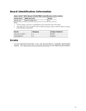
... of the board. 2. The Intel® QS77 PCH and Intel® Core™ i5-3427U processor used on the component side of the following components: Device Intel Core i5-3427U Intel BD82QS77 Stepping L1 C1 S-Spec Numbers... SR0N7 5A002U Errata Current characterized errata, if any, are documented in a separate Specification Update. iii See www.intel.com/nextunitofcomputing for the latest documentation. Board Identification Information Basic Intel® NUC Board D53427RKE Identification Information AA Revision BIOS...
... of the board. 2. The Intel® QS77 PCH and Intel® Core™ i5-3427U processor used on the component side of the following components: Device Intel Core i5-3427U Intel BD82QS77 Stepping L1 C1 S-Spec Numbers... SR0N7 5A002U Errata Current characterized errata, if any, are documented in a separate Specification Update. iii See www.intel.com/nextunitofcomputing for the latest documentation. Board Identification Information Basic Intel® NUC Board D53427RKE Identification Information AA Revision BIOS...
Technical Product Specification
Page 5
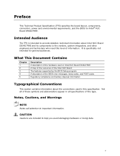
... important information. What This Document Contains Chapter 1 2 3 4 5 Description A description of the hardware used on Intel NUC Board D53427RKE A map of the resources of the Intel NUC Board The features supported by the BIOS Setup program A description of the BIOS error messages, beep codes, and POST codes Regulatory compliance and battery disposal information Typographical Conventions...
... important information. What This Document Contains Chapter 1 2 3 4 5 Description A description of the hardware used on Intel NUC Board D53427RKE A map of the resources of the Intel NUC Board The features supported by the BIOS Setup program A description of the BIOS error messages, beep codes, and POST codes Regulatory compliance and battery disposal information Typographical Conventions...
Technical Product Specification
Page 8
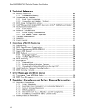
... 2 Technical Reference 2.1 Memory Resources 41 2.1.1 Addressable Memory 41 2.2 Connectors and Headers 42 2.2.1 Back Panel Connectors 43 2.2.2 Connectors and Headers (Bottom 44 2.3 BIOS Setup Configuration Jumper 52 2.4 Intel® Management Engine BIOS Extension (Intel® MEBX) Reset Header . 53 2.5 Mechanical Considerations 55 2.5.1 Form Factor 55 2.6 Electrical Considerations 56 2.6.1 Power Supply Considerations 56 2.6.2 Fan Header Current...
... 2 Technical Reference 2.1 Memory Resources 41 2.1.1 Addressable Memory 41 2.2 Connectors and Headers 42 2.2.1 Back Panel Connectors 43 2.2.2 Connectors and Headers (Bottom 44 2.3 BIOS Setup Configuration Jumper 52 2.4 Intel® Management Engine BIOS Extension (Intel® MEBX) Reset Header . 53 2.5 Mechanical Considerations 55 2.5.1 Form Factor 55 2.6 Electrical Considerations 56 2.6.1 Power Supply Considerations 56 2.6.2 Fan Header Current...

Technical Product Specification
Page 9
... Configuration 21 5. Back Panel Connectors 43 9. Connection Diagram for Components 59 20. Intel MEBX Reset Header 54 14. Board Dimensions 55 15. Front Panel Header 49 15. BIOS Setup Configuration Jumper Settings 53 17. Thermal Considerations for Front Panel Header 50 11...Components (Top 13 2. LAN Connector LED Locations 28 6. Location of the BIOS Configuration Setup Jumper 52 13. Connectors and Headers (Bottom 44 10. Location of the Standby Power LED 35 8. Intel Visual BIOS Home Screen 61 Tables 1. Feature Summary 11 2. Components Shown in Figure ...
... Configuration 21 5. Back Panel Connectors 43 9. Connection Diagram for Components 59 20. Intel MEBX Reset Header 54 14. Board Dimensions 55 15. Front Panel Header 49 15. BIOS Setup Configuration Jumper Settings 53 17. Thermal Considerations for Front Panel Header 50 11...Components (Top 13 2. LAN Connector LED Locations 28 6. Location of the BIOS Configuration Setup Jumper 52 13. Connectors and Headers (Bottom 44 10. Location of the Standby Power LED 35 8. Intel Visual BIOS Home Screen 61 Tables 1. Feature Summary 11 2. Components Shown in Figure ...

Technical Product Specification
Page 10
Safety Standards 71 29. BIOS Error Messages 69 28. Intel NUC D53427RKE Technical Product Specification 27. EMC Regulations 74 30. Regulatory Compliance Marks 77 x
Safety Standards 71 29. BIOS Error Messages 69 28. Intel NUC D53427RKE Technical Product Specification 27. EMC Regulations 74 30. Regulatory Compliance Marks 77 x

Technical Product Specification
Page 11
... board. Feature Summary Form Factor Processor Memory Chipset Graphics Audio Peripheral Interfaces Expansion Capabilities Intel® Visual BIOS 4.0 inches by 4.0 inches (101.60 millimeters by 101.60 millimeters) • Soldered-down Intel® Core™ i5-3427U processor with up to 17 W TDP ―...connector (blue) • One PCI Express Half-Mini Card connector • One PCI Express Full-Mini Card connector • Intel® Visual BIOS resident in the Serial Peripheral Interface (SPI) Flash device • Support for Advanced Configuration and Power Interface (ACPI), Plug and ...
... board. Feature Summary Form Factor Processor Memory Chipset Graphics Audio Peripheral Interfaces Expansion Capabilities Intel® Visual BIOS 4.0 inches by 4.0 inches (101.60 millimeters by 101.60 millimeters) • Soldered-down Intel® Core™ i5-3427U processor with up to 17 W TDP ―...connector (blue) • One PCI Express Half-Mini Card connector • One PCI Express Full-Mini Card connector • Intel® Visual BIOS resident in the Serial Peripheral Interface (SPI) Flash device • Support for Advanced Configuration and Power Interface (ACPI), Plug and ...
Technical Product Specification
Page 18
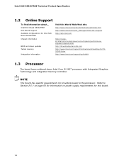
... board has specific requirements for this World Wide Web site: http://www.intel.com/products/motherboard/index.htm http://www.intel.com/p/en_US/support?iid=hdr+support http://ark.intel.com Chipset information BIOS and driver updates Tested memory Integration information https://wwwssl.intel.com/content/www/us/en/chipsets/performancechipsets/chipsets.html http://downloadcenter...
... board has specific requirements for this World Wide Web site: http://www.intel.com/products/motherboard/index.htm http://www.intel.com/p/en_US/support?iid=hdr+support http://ark.intel.com Chipset information BIOS and driver updates Tested memory Integration information https://wwwssl.intel.com/content/www/us/en/chipsets/performancechipsets/chipsets.html http://downloadcenter...
Technical Product Specification
Page 19
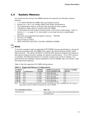
This allows the BIOS to read the SPD data and program the chipset to accurately configure memory settings for 1.35 V Low Voltage ... board should be impacted or the SO-DIMMs may not function under the determined frequency. If non-SPD memory is installed, the BIOS will attempt to single-sided memory modules (containing one row of addressable memory. • Minimum recommended total system memory: 1024 MB...compliant with SO-DIMMs that support the Serial Presence Detect (SPD) data structure. Refer to : http://support.intel.com/support/motherboards/desktop/sb /CS-025414.htm 19 Table 4.
This allows the BIOS to read the SPD data and program the chipset to accurately configure memory settings for 1.35 V Low Voltage ... board should be impacted or the SO-DIMMs may not function under the determined frequency. If non-SPD memory is installed, the BIOS will attempt to single-sided memory modules (containing one row of addressable memory. • Minimum recommended total system memory: 1024 MB...compliant with SO-DIMMs that support the Serial Presence Detect (SPD) data structure. Refer to : http://support.intel.com/support/motherboards/desktop/sb /CS-025414.htm 19 Table 4.
Technical Product Specification
Page 25
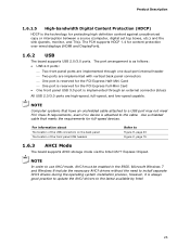
...monitor, and TVs). NOTE In order to Figure 9, page 43 Figure 2, page 15 1.6.3 AHCI Mode The board supports AHCI storage mode via the Intel QS77 Express Chipset. Microsoft Windows 7 and Windows 8 include the necessary AHCI drivers without the need to install separate AHCI drivers during the operating system installation...the back panel The location of the front panel USB headers Refer to use AHCI mode, AHCI must be enabled in the BIOS. NOTE Computer systems that meets the requirements for content protection over wired displays (HDMI and DisplayPort). 1.6.2 USB The board supports USB 2.0/3.0 ...
...monitor, and TVs). NOTE In order to Figure 9, page 43 Figure 2, page 15 1.6.3 AHCI Mode The board supports AHCI storage mode via the Intel QS77 Express Chipset. Microsoft Windows 7 and Windows 8 include the necessary AHCI drivers without the need to install separate AHCI drivers during the operating system installation...the back panel The location of the front panel USB headers Refer to use AHCI mode, AHCI must be enabled in the BIOS. NOTE Computer systems that meets the requirements for content protection over wired displays (HDMI and DisplayPort). 1.6.2 USB The board supports USB 2.0/3.0 ...
Technical Product Specification
Page 26
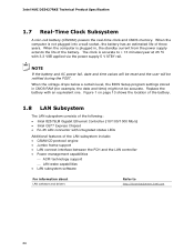
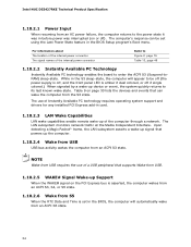
When the voltage drops below a certain level, the BIOS Setup program settings stored in , the standby current from the power supply extends the life of the battery. Replace the battery with 3.3 VSB applied via ...;C with an equivalent one. Figure 1 on page 13 shows the location of the battery. 1.8 LAN Subsystem The LAN subsystem consists of the following: • Intel 82579LM Gigabit Ethernet Controller (10/100/1000 Mb/s) • Intel QS77 Express Chipset • RJ-45 LAN connector with integrated status LEDs Additional features of three years...
When the voltage drops below a certain level, the BIOS Setup program settings stored in , the standby current from the power supply extends the life of the battery. Replace the battery with 3.3 VSB applied via ...;C with an equivalent one. Figure 1 on page 13 shows the location of the battery. 1.8 LAN Subsystem The LAN subsystem consists of the following: • Intel 82579LM Gigabit Ethernet Controller (10/100/1000 Mb/s) • Intel QS77 Express Chipset • RJ-45 LAN connector with integrated status LEDs Additional features of three years...
Technical Product Specification
Page 34
... connector The signal names of the computer through a network. While in the S3 sleep-state, the computer will automatically wake from an ACPI S3 state. Intel NUC D53427RKE Technical Product Specification 1.10.2.1 Power Input When resuming from an AC power failure, the computer returns to the power state it was in... that can be off (the power supply is off, and the front panel LED is set in the BIOS, the computer will appear to be set using the Last Power State feature in the BIOS Setup program's Boot menu. Table 9 on or off if single colored.) When signaled by a wake-up of...
... connector The signal names of the computer through a network. While in the S3 sleep-state, the computer will automatically wake from an ACPI S3 state. Intel NUC D53427RKE Technical Product Specification 1.10.2.1 Power Input When resuming from an AC power failure, the computer returns to the power state it was in... that can be off (the power supply is off, and the front panel LED is set in the BIOS, the computer will appear to be set using the Last Power State feature in the BIOS Setup program's Boot menu. Table 9 on or off if single colored.) When signaled by a wake-up of...
Technical Product Specification
Page 37
... that , when combined with a chipset, BIOS, enabling software and/or operating system, device drivers, and applications designed for this feature. For information about Intel Virtualization Technology for Directed I/O (Intel® VT-d) allows addresses in incoming I/O device memory transactions to be remapped to different host addresses. For information about Intel Active Management Technology Refer to...
... that , when combined with a chipset, BIOS, enabling software and/or operating system, device drivers, and applications designed for this feature. For information about Intel Virtualization Technology for Directed I/O (Intel® VT-d) allows addresses in incoming I/O device memory transactions to be remapped to different host addresses. For information about Intel Active Management Technology Refer to...

Technical Product Specification
Page 38
...-resistant defense that works like a poison pill that protects systems against a known good source. For information about Intel Anti-Theft Refer to have an Intel® AT-enabled chipset, BIOS, firmware release, software, and an Intel AT-capable Service Provider/ISV application and service subscription. NOTE No computer system can provide absolute security under...
...-resistant defense that works like a poison pill that protects systems against a known good source. For information about Intel Anti-Theft Refer to have an Intel® AT-enabled chipset, BIOS, firmware release, software, and an Intel AT-capable Service Provider/ISV application and service subscription. NOTE No computer system can provide absolute security under...

Technical Product Specification
Page 41
These functions include the following: • BIOS/SPI Flash device (128 Mb) • Local APIC (19 MB) • Direct Media Interface (40 MB) • PCI Express configuration space (256 MB) • PCH ... of addressable system memory. All installed system memory can be used when there is allocated for PCI Express add-in cards, PCI Express configuration space, BIOS (SPI Flash device), and chipset overhead resides above the 4 GB boundary. Typically the address space that is no overlap of usable DRAM boundary to the...
These functions include the following: • BIOS/SPI Flash device (128 Mb) • Local APIC (19 MB) • Direct Media Interface (40 MB) • PCI Express configuration space (256 MB) • PCH ... of addressable system memory. All installed system memory can be used when there is allocated for PCI Express add-in cards, PCI Express configuration space, BIOS (SPI Flash device), and chipset overhead resides above the 4 GB boundary. Typically the address space that is no overlap of usable DRAM boundary to the...
Technical Product Specification
Page 50
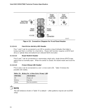
... LED behavior shown in Table 15 is closed, the board resets and runs the POST. 2.2.2.4.3 Power/Sleep LED Header Pins 2 and 4 can be set via BIOS setup. 50 Intel NUC D53427RKE Technical Product Specification Figure 10. When the switch is default - or two-color LED. Table 15.
... LED behavior shown in Table 15 is closed, the board resets and runs the POST. 2.2.2.4.3 Power/Sleep LED Header Pins 2 and 4 can be set via BIOS setup. 50 Intel NUC D53427RKE Technical Product Specification Figure 10. When the switch is default - or two-color LED. Table 15.
Technical Product Specification
Page 52
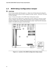
Intel NUC D53427RKE Technical Product Specification 2.3 BIOS Setup Configuration Jumper CAUTION Do not move a jumper with the power on. Table 16 describes the BIOS Setup configuration jumper settings for the three modes: normal, configure, and recovery. Location of the BIOS Setup Configuration jumper. Always turn off the power ... changing a jumper setting. When the jumper is set to configure mode and the computer is powered-up, the BIOS compares the processor version and the microcode version in the BIOS and reports if the two match. Figure 12. Figure 13 shows the location of the...
Intel NUC D53427RKE Technical Product Specification 2.3 BIOS Setup Configuration Jumper CAUTION Do not move a jumper with the power on. Table 16 describes the BIOS Setup configuration jumper settings for the three modes: normal, configure, and recovery. Location of the BIOS Setup Configuration jumper. Always turn off the power ... changing a jumper setting. When the jumper is set to configure mode and the computer is powered-up, the BIOS compares the processor version and the microcode version in the BIOS and reports if the two match. Figure 12. Figure 13 shows the location of the...

Technical Product Specification
Page 53
...before reapplying power. The maintenance menu is the only way to the factory defaults. Recovery None The BIOS attempts to their default values. • Reset the Intel MEBX password to reach end of POST before installing an MEBX reset jumper. CAUTION Always turn off the...following: • Return all Intel ME parameters to their default values. This is required. 2.4 Intel® Management Engine BIOS Extension (Intel® MEBX) Reset Header The Intel® MEBX reset header (see Figure 13) allows you to reset the Intel ME configuration to clear the BIOS/CMOS settings. Table 16. ...
...before reapplying power. The maintenance menu is the only way to the factory defaults. Recovery None The BIOS attempts to their default values. • Reset the Intel MEBX password to reach end of POST before installing an MEBX reset jumper. CAUTION Always turn off the...following: • Return all Intel ME parameters to their default values. This is required. 2.4 Intel® Management Engine BIOS Extension (Intel® MEBX) Reset Header The Intel® MEBX reset header (see Figure 13) allows you to reset the Intel ME configuration to clear the BIOS/CMOS settings. Table 16. ...

Technical Product Specification
Page 59
...when considering proper airflow to the Maximum Case Temperature. Maximum case temperatures are sensitive to Section 1.2, page 18 http://www.intel.com/Products/Desktop/ Chipsets/ec-QS77/QS77technicaldocuments.htm 59 When the component is a value reported by the components). Technical Reference... Table 19 provides maximum case temperatures for the components that the temperature measurement in the system BIOS is dissipating less than TDP, the case temperature should be dissipated by embedded thermal sensors in Table 20. Tcontrol Values...
...when considering proper airflow to the Maximum Case Temperature. Maximum case temperatures are sensitive to Section 1.2, page 18 http://www.intel.com/Products/Desktop/ Chipsets/ec-QS77/QS77technicaldocuments.htm 59 When the component is a value reported by the components). Technical Reference... Table 19 provides maximum case temperatures for the components that the temperature measurement in the system BIOS is dissipating less than TDP, the case temperature should be dissipated by embedded thermal sensors in Table 20. Tcontrol Values...

Technical Product Specification
Page 61
...be used to view and change the BIOS settings for the computer. 3 Overview of BIOS and a revision code. Intel Visual BIOS Home Screen 61 When the BIOS Setup configuration jumper is set to configure mode and the computer is powered-up, the BIOS compares the CPU version and the ...the PCI auto-configuration utility, LAN EEPROM information, and Plug and Play support. The BIOS displays a message during POST identifying the type of BIOS Features 3.1 Introduction The board uses an Intel® Visual BIOS that is accessed by pressing the key after the Power-On Self-Test (POST) memory...
...be used to view and change the BIOS settings for the computer. 3 Overview of BIOS and a revision code. Intel Visual BIOS Home Screen 61 When the BIOS Setup configuration jumper is set to configure mode and the computer is powered-up, the BIOS compares the CPU version and the ...the PCI auto-configuration utility, LAN EEPROM information, and Plug and Play support. The BIOS displays a message during POST identifying the type of BIOS Features 3.1 Introduction The board uses an Intel® Visual BIOS that is accessed by pressing the key after the Power-On Self-Test (POST) memory...


