
Product Guide
Page 4
...rear panel USB 2.0/IEEE 1394 adapter • One front panel USB 2.0/IEEE 1394/audio adapter • Intel® Express Installer CD-ROM • Floppy disk with RAID driver • Back panel audio covers • Quick Reference Guide • Integration Guide • Printed Product ...Guide • Configuration and battery caution statement label iv Intel Desktop Board D925XCV/D925XBC Product Guide Terminology The table below gives descriptions to...
...rear panel USB 2.0/IEEE 1394 adapter • One front panel USB 2.0/IEEE 1394/audio adapter • Intel® Express Installer CD-ROM • Floppy disk with RAID driver • Back panel audio covers • Quick Reference Guide • Integration Guide • Printed Product ...Guide • Configuration and battery caution statement label iv Intel Desktop Board D925XCV/D925XBC Product Guide Terminology The table below gives descriptions to...
Product Guide
Page 5
Contents 1 Desktop Board Features 9 Supported Operating Systems 10 Desktop Board Components 11 Processor ...15 Main Memory ...16 Intel® 925X Express Chipset 17 Audio Subsystem ...17 Input/Output (I/O) Controller 18 LAN Subsystem ...18 LAN Subsystem Software 18 RJ-45 LAN Connector LEDs 18 ... Express Auto Configuration 20 Security Passwords...20 Chassis Intrusion...20 Power Management Features 21 ACPI...21 Fan Connectors...21 Fan Speed Control (Intel® Precision Cooling Technology 21 Suspend to RAM (Instantly Available PC Technology 22 Resume on Ring ...23 Wake from USB ...23...
Contents 1 Desktop Board Features 9 Supported Operating Systems 10 Desktop Board Components 11 Processor ...15 Main Memory ...16 Intel® 925X Express Chipset 17 Audio Subsystem ...17 Input/Output (I/O) Controller 18 LAN Subsystem ...18 LAN Subsystem Software 18 RJ-45 LAN Connector LEDs 18 ... Express Auto Configuration 20 Security Passwords...20 Chassis Intrusion...20 Power Management Features 21 ACPI...21 Fan Connectors...21 Fan Speed Control (Intel® Precision Cooling Technology 21 Suspend to RAM (Instantly Available PC Technology 22 Resume on Ring ...23 Wake from USB ...23...

Product Guide
Page 6
... Panel USB 2.0 and IEEE 1394 Adapter 46 Installing the Front Panel USB/IEEE 1394/Audio Solution 47 Connecting Fans...48 Connecting Fans...48 Connecting the Auxiliary Power Output Connector (D925XCV only 49 Connecting Power Cables 50 Installing Other Connectors 52 Setting the BIOS Configuration Jumper ...55 Setting Up Full 7.1-Channel Surround Sound (Optional 56 Multi-Channel Analog Audio 56 Multi-Channel Digital Audio 56 Replacing the Battery...57 3 BIOS Updating the BIOS...61 Updating the BIOS with the Intel® Express BIOS Update Utility 61 Updating the BIOS with the Iflash Memory...
... Panel USB 2.0 and IEEE 1394 Adapter 46 Installing the Front Panel USB/IEEE 1394/Audio Solution 47 Connecting Fans...48 Connecting Fans...48 Connecting the Auxiliary Power Output Connector (D925XCV only 49 Connecting Power Cables 50 Installing Other Connectors 52 Setting the BIOS Configuration Jumper ...55 Setting Up Full 7.1-Channel Surround Sound (Optional 56 Multi-Channel Analog Audio 56 Multi-Channel Digital Audio 56 Replacing the Battery...57 3 BIOS Updating the BIOS...61 Updating the BIOS with the Intel® Express BIOS Update Utility 61 Updating the BIOS with the Iflash Memory...
Product Guide
Page 7
...Error Messages ...67 B Regulatory Compliance Safety Regulations ...69 European Union Declaration of the BIOS Configuration Jumper Block 53 29. Desktop Board D925XCV Components 11 2. Lift Socket Lever...30 7. Install Processor ...32 11. Connecting the Processor Fan Heat Sink Cable to the Processor Fan...Dual Configuration Example 2 34 15. Use DDR2 DIMMs ...36 17. Installing a DIMM...37 18. Connecting the Front Panel USB/IEEE1394/Audio Cables 47 24. Connecting 2x10 Power Supply Cables 50 26. Location of Conformity Statement 69 Product Ecology Statements 70 EMC Regulations ...71...
...Error Messages ...67 B Regulatory Compliance Safety Regulations ...69 European Union Declaration of the BIOS Configuration Jumper Block 53 29. Desktop Board D925XCV Components 11 2. Lift Socket Lever...30 7. Install Processor ...32 11. Connecting the Processor Fan Heat Sink Cable to the Processor Fan...Dual Configuration Example 2 34 15. Use DDR2 DIMMs ...36 17. Installing a DIMM...37 18. Connecting the Front Panel USB/IEEE1394/Audio Cables 47 24. Connecting 2x10 Power Supply Cables 50 26. Location of Conformity Statement 69 Product Ecology Statements 70 EMC Regulations ...71...

Product Guide
Page 8
.... Product Certification Markings 72 viii Front Panel Header Signal Names 45 10. Interrupts ...66 14. Safety Regulations ...69 17. Desktop Board D925XCV Components 12 3. IEEE 1394 Header Signal Names 44 8. EMC Regulations...71 18. Beep Codes...67 15. USB 2.0 Header Signal Names... 44 9. System Memory Map...65 12. Front Panel Audio Header Signal Names 44 7. Intel Desktop Board D925XCV/D925XBC Product Guide Tables 1. Feature Summary...9 2. RJ-45 10/100/1000 Gigabit Ethernet LAN Connector LEDs 18 6. ...
.... Product Certification Markings 72 viii Front Panel Header Signal Names 45 10. Interrupts ...66 14. Safety Regulations ...69 17. Desktop Board D925XCV Components 12 3. IEEE 1394 Header Signal Names 44 8. EMC Regulations...71 18. Beep Codes...67 15. USB 2.0 Header Signal Names... 44 9. System Memory Map...65 12. Front Panel Audio Header Signal Names 44 7. Intel Desktop Board D925XCV/D925XBC Product Guide Tables 1. Feature Summary...9 2. RJ-45 10/100/1000 Gigabit Ethernet LAN Connector LEDs 18 6. ...

Product Guide
Page 9
.... Feature Summary Form Factor Processor Main Memory Chipset Audio Expansion Capabilities • ATX (12.00" x 9.60") Intel Desktop Board D925XCV • MicroATX (9.60" x 9.60") Intel Desktop Board D925XBC Support for an Intel® Pentium® 4 processor in the LGA775...with Direct Media Interface • Intel® 82801FR I/O Controller Hub (ICH6-R) supporting Intel® Matrix Storage Technology • Intel 925X Express Chipset • Intel® high-definition audio codec • Up to four (Intel Desktop Board D925XCV) or two (Intel Desktop Board D925XBC) PCI bus...
.... Feature Summary Form Factor Processor Main Memory Chipset Audio Expansion Capabilities • ATX (12.00" x 9.60") Intel Desktop Board D925XCV • MicroATX (9.60" x 9.60") Intel Desktop Board D925XBC Support for an Intel® Pentium® 4 processor in the LGA775...with Direct Media Interface • Intel® 82801FR I/O Controller Hub (ICH6-R) supporting Intel® Matrix Storage Technology • Intel 925X Express Chipset • Intel® high-definition audio codec • Up to four (Intel Desktop Board D925XCV) or two (Intel Desktop Board D925XBC) PCI bus...

Product Guide
Page 12
Intel Desktop Board D925XCV/D925XBC Product Guide Table 2. Label A B C D E F G H I J K L M N O P Q R S T U V W X Desktop Board D925XCV Components Description PCI Express x1 connectors Front panel audio header (yellow) PCI Express x16 connector Rear chassis fan header (fan speed control) Alternate power connector (1x4) 12 V power connector (2x2) Processor socket (LGA775) Processor ...
Intel Desktop Board D925XCV/D925XBC Product Guide Table 2. Label A B C D E F G H I J K L M N O P Q R S T U V W X Desktop Board D925XCV Components Description PCI Express x1 connectors Front panel audio header (yellow) PCI Express x16 connector Rear chassis fan header (fan speed control) Alternate power connector (1x4) 12 V power connector (2x2) Processor socket (LGA775) Processor ...

Product Guide
Page 14
... Links Go to the following links for more information about: • Intel Desktop Board D925XCV/D925XBC http://www.intel.com/design/motherbd http://support.intel.com/support/motherboards/desktop • Supported processors http://support.intel.com/support/motherboards/desktop • Audio software and utilities http://www.intel.com/design/motherbd • LAN software and drivers http://www...
... Links Go to the following links for more information about: • Intel Desktop Board D925XCV/D925XBC http://www.intel.com/design/motherbd http://support.intel.com/support/motherboards/desktop • Supported processors http://support.intel.com/support/motherboards/desktop • Audio software and utilities http://www.intel.com/design/motherbd • LAN software and drivers http://www...
Product Guide
Page 17
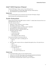
... (ICH6-R) Related Link Go to the following link for more information about the Intel 925X Express Chipset: http://developer.intel.com/design/nav/pcserver.htm Audio Subsystem Desktop Board D925XCV/D925XBC includes a flexible 7.1-channel audio subsystem based on an Intel high-definition audio codec: The audio subsystem features: • Impedance sensing capability for jack re-tasking • S/N (signal...
... (ICH6-R) Related Link Go to the following link for more information about the Intel 925X Express Chipset: http://developer.intel.com/design/nav/pcserver.htm Audio Subsystem Desktop Board D925XCV/D925XBC includes a flexible 7.1-channel audio subsystem based on an Intel high-definition audio codec: The audio subsystem features: • Impedance sensing capability for jack re-tasking • S/N (signal...
Product Guide
Page 25
...configuration jumper • Clear passwords • Identify back panel connectors • Set up a log to record information about your system for Intel Matrix Storage Technology for using an antistatic wrist strap and a conductive foam pad. Perform the procedures described in the correct order. •... Set up multi-channel audio • Replace the battery Before You Begin WARNING The procedures in this chapter only at an ESD workstation using and modifying electronic...
...configuration jumper • Clear passwords • Identify back panel connectors • Set up a log to record information about your system for Intel Matrix Storage Technology for using an antistatic wrist strap and a conductive foam pad. Perform the procedures described in the correct order. •... Set up multi-channel audio • Replace the battery Before You Begin WARNING The procedures in this chapter only at an ESD workstation using and modifying electronic...

Product Guide
Page 43
... On/Off 87 65 Reset Power LED 43 HD LED 3 21 1 C B Item A B C D E F Description Chassis intrusion Alternate power LED Front panel USB 2.0 IEEE 1394 Front panel audio Figure 21. Internal Headers 1 A OM16934 43 Installing and Replacing Desktop Board Components Connecting Internal Headers Before connecting cables to the internal headers, observe the precautions...
... On/Off 87 65 Reset Power LED 43 HD LED 3 21 1 C B Item A B C D E F Description Chassis intrusion Alternate power LED Front panel USB 2.0 IEEE 1394 Front panel audio Figure 21. Internal Headers 1 A OM16934 43 Installing and Replacing Desktop Board Components Connecting Internal Headers Before connecting cables to the internal headers, observe the precautions...

Product Guide
Page 44
.... Table 7. USB Port B Pin Signal Name 2 Power 4 D- 6 D+ 8 Ground 10 No connect 44 Table 6. Intel Desktop Board D925XCV/D925XBC Product Guide Front Panel Audio Header Figure 21, F on page 43 shows the location of the blue IEEE 1394 headers. Table 6 shows the pin assignments... for the location of the yellow front panel audio header. IEEE 1394 Header Signal Names Pin Signal Name 1 TPA1+ 3 Ground...
.... Table 7. USB Port B Pin Signal Name 2 Power 4 D- 6 D+ 8 Ground 10 No connect 44 Table 6. Intel Desktop Board D925XCV/D925XBC Product Guide Front Panel Audio Header Figure 21, F on page 43 shows the location of the blue IEEE 1394 headers. Table 6 shows the pin assignments... for the location of the yellow front panel audio header. IEEE 1394 Header Signal Names Pin Signal Name 1 TPA1+ 3 Ground...

Product Guide
Page 47
... Replacing Desktop Board Components Installing the Front Panel USB/IEEE 1394/Audio Solution To install the front panel USB/IEEE1394/audio solution cables to the headers, follow these steps (see Figure 23): 1. Locate the front panel audio header (yellow), USB 2.0 header (black), and IEEE 1394 ... cover. 4. Install a correctly keyed and shielded cable. 6. Remove the cover. 4. Replace the cover. 47 Remove the front panel USB/IEEE1394/audio solution cables. 5. Replace the cover. Observe the precautions in "Before You Begin" on the desktop board. 5. Connect the cables to the computer...
... Replacing Desktop Board Components Installing the Front Panel USB/IEEE 1394/Audio Solution To install the front panel USB/IEEE1394/audio solution cables to the headers, follow these steps (see Figure 23): 1. Locate the front panel audio header (yellow), USB 2.0 header (black), and IEEE 1394 ... cover. 4. Install a correctly keyed and shielded cable. 6. Remove the cover. 4. Replace the cover. 47 Remove the front panel USB/IEEE1394/audio solution cables. 5. Replace the cover. Observe the precautions in "Before You Begin" on the desktop board. 5. Connect the cables to the computer...

Product Guide
Page 55
Poor audio quality may occur if passive (non-amplified) speakers are connected to power either headphones or amplified speakers only. Line In IEEE 1394 RJ45 Optical Line Out (Toslink) Co-axial Line Out Figure 30. Back Panel Connectors OM16931 55 Figure 30 shows the back panel connectors. Installing and Replacing Desktop Board Components Back Panel Connectors NOTE The line out connector, located on the back panel, is designed to this output.
Poor audio quality may occur if passive (non-amplified) speakers are connected to power either headphones or amplified speakers only. Line In IEEE 1394 RJ45 Optical Line Out (Toslink) Co-axial Line Out Figure 30. Back Panel Connectors OM16931 55 Figure 30 shows the back panel connectors. Installing and Replacing Desktop Board Components Back Panel Connectors NOTE The line out connector, located on the back panel, is designed to this output.

Product Guide
Page 56
... (multi-channel) Mic in Figure 31, up to the style of back panel audio connectors. Select the proper connector according to eight speakers. Multi-Channel Digital Audio Two types of S/PDIF connectors are available: coaxial (G) and optical (F). Intel Desktop Board D925XCV/D925XBC Product Guide Setting Up Full 7.1-Channel Surround Sound (Optional) After installing the...
... (multi-channel) Mic in Figure 31, up to the style of back panel audio connectors. Select the proper connector according to eight speakers. Multi-Channel Digital Audio Two types of S/PDIF connectors are available: coaxial (G) and optical (F). Intel Desktop Board D925XCV/D925XBC Product Guide Setting Up Full 7.1-Channel Surround Sound (Optional) After installing the...

Product Specification
Page 5
... 13 1.3.3 Board Layouts 14 1.3.4 Block Diagram 18 1.4 Online Support ...19 1.5 Processor ...19 1.6 System Memory ...20 1.6.1 Memory Configurations 21 1.7 Intel® 925X Chipset ...25 1.7.1 USB ...25 1.7.2 IDE Support 25 1.7.3 Real-Time Clock, CMOS SRAM, and Battery 28 1.8 PCI Express Connectors... Drive Controller 30 1.10.4 Keyboard and Mouse Interface 30 1.11 Audio Subsystem ...31 1.11.1 Audio Subsystem Software 31 1.11.2 Audio Connectors 31 1.11.3 8-Channel (7.1) Audio Subsystem 32 1.11.4 6-Channel (5.1) Audio Subsystem 34 1.12 LAN Subsystem...35 1.12.1 Marvell Yukon 88E8050 ...
... 13 1.3.3 Board Layouts 14 1.3.4 Block Diagram 18 1.4 Online Support ...19 1.5 Processor ...19 1.6 System Memory ...20 1.6.1 Memory Configurations 21 1.7 Intel® 925X Chipset ...25 1.7.1 USB ...25 1.7.2 IDE Support 25 1.7.3 Real-Time Clock, CMOS SRAM, and Battery 28 1.8 PCI Express Connectors... Drive Controller 30 1.10.4 Keyboard and Mouse Interface 30 1.11 Audio Subsystem ...31 1.11.1 Audio Subsystem Software 31 1.11.2 Audio Connectors 31 1.11.3 8-Channel (7.1) Audio Subsystem 32 1.11.4 6-Channel (5.1) Audio Subsystem 34 1.12 LAN Subsystem...35 1.12.1 Marvell Yukon 88E8050 ...

Product Specification
Page 8
Intel Desktop Boards D925XCV/D925XBC Technical Product Specification Figures 1. Block Diagram ...18 4. Dual Channel (Interleaved) Mode Configuration with One DIMM 24 9. Single Channel (Asymmetric) Mode Configuration with Two DIMMs 22 6. Thermal Monitoring for Boards with the 8-Channel (7.1) Audio Subsystem ...........83 30. ... Map 56 19. Desktop Board D925XBC Dimensions 82 29. Processor Heatsink for 6-Channel (5.1) Audio Subsystem 66 21. Summary of the Jumper Block 80 27. D925XCV Components Shown in Figure 2 17 6. Power States and Targeted System Power 42 10. ...
Intel Desktop Boards D925XCV/D925XBC Technical Product Specification Figures 1. Block Diagram ...18 4. Dual Channel (Interleaved) Mode Configuration with One DIMM 24 9. Single Channel (Asymmetric) Mode Configuration with Two DIMMs 22 6. Thermal Monitoring for Boards with the 8-Channel (7.1) Audio Subsystem ...........83 30. ... Map 56 19. Desktop Board D925XBC Dimensions 82 29. Processor Heatsink for 6-Channel (5.1) Audio Subsystem 66 21. Summary of the Jumper Block 80 27. D925XCV Components Shown in Figure 2 17 6. Power States and Targeted System Power 42 10. ...

Product Specification
Page 9
...Boot Device Menu Options 99 47. BIOS Error Messages 103 49. D925XBC Component-side Connectors Shown in Figure 22 71 21. Front Panel Audio Connector 72 23. Processor Fan Connector and Auxiliary Rear Fan Connector 72 25. Auxiliary Power Output Connector 73 29. Safety Regulations ...91...Chassis Fan Connectors 72 24. States for a Two-Color Power LED 77 36. BIOS Setup Configuration Jumper Settings 80 37. Desktop Boards D925XCV/D925XBC Environmental Specifications 90 41. Boot Block Recovery Code Checkpoints 105 51. PCI Configuration Space Map 59 15. Main Power Connector 75 30...
...Boot Device Menu Options 99 47. BIOS Error Messages 103 49. D925XBC Component-side Connectors Shown in Figure 22 71 21. Front Panel Audio Connector 72 23. Processor Fan Connector and Auxiliary Rear Fan Connector 72 25. Auxiliary Power Output Connector 73 29. Safety Regulations ...91...Chassis Fan Connectors 72 24. States for a Two-Color Power LED 77 36. BIOS Setup Configuration Jumper Settings 80 37. Desktop Boards D925XCV/D925XBC Environmental Specifications 90 41. Boot Block Recovery Code Checkpoints 105 51. PCI Configuration Space Map 59 15. Main Power Connector 75 30...

Product Specification
Page 11
...8226; Option for SCSI hard drive indicator LED • Option for add-in card connector 11 Table 1. Summary of Board Differences D925XCV D925XBC • ATX Form Factor (12.00 inches by 9.60 inches [304.80 millimeters by 243.84 millimeters]) • ...Overview ...12 1.4 Online Support ...19 1.5 Processor ...19 1.6 System Memory ...20 1.7 Intel® 925X Chipset 25 1.8 PCI Express Connectors 28 1.9 Auxiliary Power (AUX PWR) Output Connector 28 1.10 I/O Controller...29 1.11 Audio Subsystem ...31 1.12 LAN Subsystem...35 1.13 Hardware Management Subsystem 37 1.14 Power Management...
...8226; Option for SCSI hard drive indicator LED • Option for add-in card connector 11 Table 1. Summary of Board Differences D925XCV D925XBC • ATX Form Factor (12.00 inches by 9.60 inches [304.80 millimeters by 243.84 millimeters]) • ...Overview ...12 1.4 Online Support ...19 1.5 Processor ...19 1.6 System Memory ...20 1.7 Intel® 925X Chipset 25 1.8 PCI Express Connectors 28 1.9 Auxiliary Power (AUX PWR) Output Connector 28 1.10 I/O Controller...29 1.11 Audio Subsystem ...31 1.12 LAN Subsystem...35 1.13 Hardware Management Subsystem 37 1.14 Power Management...

Product Specification
Page 12
...Video Audio I/O Control USB Peripheral Interfaces BIOS Instantly Available PC Technology • D925XCV: ATX (12.00 inches by 9.60 inches [304.80 millimeters by 243.84 millimeters]) • D925XBC: microATX (9.60 inches by 9.60 inches [243.84 millimeters by 243.84 millimeters]) Support for an Intel&#... up to RAM support • Wake on PCI, RS-232, front panel, PS/2 devices, and USB ports continued 12 Table 2. Intel Desktop Boards D925XCV/D925XBC Technical Product Specification ✏ NOTE Most of the illustrations in the 8 Mbit FWH) • Support for Advanced Configuration and Power...
...Video Audio I/O Control USB Peripheral Interfaces BIOS Instantly Available PC Technology • D925XCV: ATX (12.00 inches by 9.60 inches [304.80 millimeters by 243.84 millimeters]) • D925XBC: microATX (9.60 inches by 9.60 inches [243.84 millimeters by 243.84 millimeters]) Support for an Intel&#... up to RAM support • Wake on PCI, RS-232, front panel, PS/2 devices, and USB ports continued 12 Table 2. Intel Desktop Boards D925XCV/D925XBC Technical Product Specification ✏ NOTE Most of the illustrations in the 8 Mbit FWH) • Support for Advanced Configuration and Power...


