
Product Guide
Page 5
Contents 1 Desktop Board Features 9 Supported Operating Systems 10 Desktop Board Components 11 Processor ...15 Main Memory ...16 Intel® 925X Express Chipset 17 Audio Subsystem ...17 Input/Output (I/O) Controller 18 LAN Subsystem ...18 LAN Subsystem Software 18 RJ-45 LAN ...PCI and PCI Express Auto Configuration 20 Security Passwords...20 Chassis Intrusion...20 Power Management Features 21 ACPI...21 Fan Connectors...21 Fan Speed Control (Intel® Precision Cooling Technology 21 Suspend to RAM (Instantly Available PC Technology 22 Resume on Ring ...23 Wake from USB ...23 Wake from...
Contents 1 Desktop Board Features 9 Supported Operating Systems 10 Desktop Board Components 11 Processor ...15 Main Memory ...16 Intel® 925X Express Chipset 17 Audio Subsystem ...17 Input/Output (I/O) Controller 18 LAN Subsystem ...18 LAN Subsystem Software 18 RJ-45 LAN ...PCI and PCI Express Auto Configuration 20 Security Passwords...20 Chassis Intrusion...20 Power Management Features 21 ACPI...21 Fan Connectors...21 Fan Speed Control (Intel® Precision Cooling Technology 21 Suspend to RAM (Instantly Available PC Technology 22 Resume on Ring ...23 Wake from USB ...23 Wake from...

Product Guide
Page 6
Intel Desktop Board D925XCV/D925XBC Product Guide Installing a Processor 30 Installing the Processor Fan Heat Sink 32 Connecting the Processor Fan Heat Sink Cable 33 Removing the Processor 33 Installing and Removing Memory 34 Installing DIMMs ...36 Removing DIMMs...38 Installing and Removing a PCI Express x16 Card 38 Installing a PCI Express x16 Card ...
Intel Desktop Board D925XCV/D925XBC Product Guide Installing a Processor 30 Installing the Processor Fan Heat Sink 32 Connecting the Processor Fan Heat Sink Cable 33 Removing the Processor 33 Installing and Removing Memory 34 Installing DIMMs ...36 Removing DIMMs...38 Installing and Removing a PCI Express x16 Card 38 Installing a PCI Express x16 Card ...
Product Guide
Page 7
... Power Indicator 22 4. Location of the BIOS Configuration Jumper Block 53 29. Location of Other Connectors 52 28. Remove the Processor from the Protective Processor Cover/Do Not Touch 31 10. Use DDR2 DIMMs ...36 17. Internal Headers ...43 22. Connecting 2x10 Power Supply Cables...47 24. Back Panel Audio Connectors 56 31. Installing a DIMM...37 18. Install Processor ...32 11. Connecting the Serial ATA Cable 41 21. Connecting 2x12 Power Supply Cables 51 27. Desktop Board D925XCV Components 11 2. Dual Configuration Example 2 34 15. Removing the Battery ...60 vii...
... Power Indicator 22 4. Location of the BIOS Configuration Jumper Block 53 29. Location of Other Connectors 52 28. Remove the Processor from the Protective Processor Cover/Do Not Touch 31 10. Use DDR2 DIMMs ...36 17. Internal Headers ...43 22. Connecting 2x10 Power Supply Cables...47 24. Back Panel Audio Connectors 56 31. Installing a DIMM...37 18. Install Processor ...32 11. Connecting the Serial ATA Cable 41 21. Connecting 2x12 Power Supply Cables 51 27. Desktop Board D925XCV Components 11 2. Dual Configuration Example 2 34 15. Removing the Battery ...60 vii...

Product Guide
Page 9
....00" x 9.60") Intel Desktop Board D925XCV • MicroATX (9.60" x 9.60") Intel Desktop Board D925XBC Support for an Intel® Pentium® 4 processor in the LGA775 package with RJ-45 connector • Intel® BIOS • 8 Mbit symmetrical flash memory • Support for SMBIOS • Intel® Rapid BIOS Boot • Intel® Express BIOS Update Intel® Matrix Storage...
....00" x 9.60") Intel Desktop Board D925XCV • MicroATX (9.60" x 9.60") Intel Desktop Board D925XBC Support for an Intel® Pentium® 4 processor in the LGA775 package with RJ-45 connector • Intel® BIOS • 8 Mbit symmetrical flash memory • Support for SMBIOS • Intel® Rapid BIOS Boot • Intel® Express BIOS Update Intel® Matrix Storage...

Product Guide
Page 10
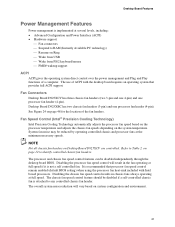
...; Precision Cooling Technology fan speed control that automatically adjusts processor fan speeds based on processor temperature and chassis fan speeds based on system temperature • Voltage sensing to detect out of range values Related Links For more information about Intel Desktop Board D925XCV/D925XBC, including the Technical Product Specification (TPS), BIOS updates, and device...
...; Precision Cooling Technology fan speed control that automatically adjusts processor fan speeds based on processor temperature and chassis fan speeds based on system temperature • Voltage sensing to detect out of range values Related Links For more information about Intel Desktop Board D925XCV/D925XBC, including the Technical Product Specification (TPS), BIOS updates, and device...

Product Guide
Page 12
... G H I J K L M N O P Q R S T U V W X Desktop Board D925XCV Components Description PCI Express x1 connectors Front panel audio header (yellow) PCI Express x16 connector Rear chassis fan header (fan speed control) Alternate power connector (1x4) 12 V power connector (2x2) Processor socket (LGA775) Processor fan header (4-pin, fan speed control) Main power connector (2x12) Diskette drive connector IDE connector Battery... 1394 headers (blue) Speaker PCI bus add-in card connectors Auxiliary rear fan header (4-pin, fan speed control) 12 Intel Desktop Board D925XCV/D925XBC Product Guide Table 2.
... G H I J K L M N O P Q R S T U V W X Desktop Board D925XCV Components Description PCI Express x1 connectors Front panel audio header (yellow) PCI Express x16 connector Rear chassis fan header (fan speed control) Alternate power connector (1x4) 12 V power connector (2x2) Processor socket (LGA775) Processor fan header (4-pin, fan speed control) Main power connector (2x12) Diskette drive connector IDE connector Battery... 1394 headers (blue) Speaker PCI bus add-in card connectors Auxiliary rear fan header (4-pin, fan speed control) 12 Intel Desktop Board D925XCV/D925XBC Product Guide Table 2.

Product Guide
Page 14
...connector Rear chassis fan header (fan speed control) Alternate power connector (1x4) 12 V power connector (2x2) Processor socket (LGA775) Processor fan header (4-pin, fan speed control) Main power connector (2x12) Diskette drive connector IDE connector Battery Chassis intrusion... about: • Intel Desktop Board D925XCV/D925XBC http://www.intel.com/design/motherbd http://support.intel.com/support/motherboards/desktop • Supported processors http://support.intel.com/support/motherboards/desktop • Audio software and utilities http://www.intel.com/design/motherbd •...
...connector Rear chassis fan header (fan speed control) Alternate power connector (1x4) 12 V power connector (2x2) Processor socket (LGA775) Processor fan header (4-pin, fan speed control) Main power connector (2x12) Diskette drive connector IDE connector Battery Chassis intrusion... about: • Intel Desktop Board D925XCV/D925XBC http://www.intel.com/design/motherbd http://support.intel.com/support/motherboards/desktop • Supported processors http://support.intel.com/support/motherboards/desktop • Audio software and utilities http://www.intel.com/design/motherbd •...

Product Guide
Page 15
... D925XBC is located on installing or upgrading the processor, page 30 in Chapter 2 • The location of the two power connectors, page 48 in the computer not booting. Desktop Boards D925XCV and D925XBC support a single Intel Pentium 4 processor in the LGA775 package. Processors are not included with the desktop board and must be purchased separately...
... D925XBC is located on installing or upgrading the processor, page 30 in Chapter 2 • The location of the two power connectors, page 48 in the computer not booting. Desktop Boards D925XCV and D925XBC support a single Intel Pentium 4 processor in the LGA775 package. Processors are not included with the desktop board and must be purchased separately...

Product Guide
Page 16
... board supports dual or single channel memory configurations defined in Chapter 2 16 Intel Desktop Board D925XCV/D925XBC Product Guide Main Memory NOTE To be fully compliant with all applicable Intel® SDRAM memory specifications, the desktop board should be populated with gold-plated..., http://www.intel.com/technology/memory/pcsdram/spec/ • Installing memory, page 34 in Table 4. The BIOS will see a notification to the operating system and applications. Memory Configurations Memory Speed DDR2 533 Processor Pentium 4 processor DDR2 400 Pentium 4 processor FSB frequency (...
... board supports dual or single channel memory configurations defined in Chapter 2 16 Intel Desktop Board D925XCV/D925XBC Product Guide Main Memory NOTE To be fully compliant with all applicable Intel® SDRAM memory specifications, the desktop board should be populated with gold-plated..., http://www.intel.com/technology/memory/pcsdram/spec/ • Installing memory, page 34 in Table 4. The BIOS will see a notification to the operating system and applications. Memory Configurations Memory Speed DDR2 533 Processor Pentium 4 processor DDR2 400 Pentium 4 processor FSB frequency (...

Product Guide
Page 19
...ATA channels via ICH6-R; USB 1.1 devices will function normally at USB 1.1 speeds. Expandability The desktop boards support the following: • Desktop board D925XCV: One PCI Express x16 add-in card Two PCI Express x1 add-in cards Four PCI bus add-in ...Use a shielded cable that fully support USB 2.0 transfer rates. Enhanced IDE Interface The ICH6-R's IDE interface handles the exchange of information between the processor and peripheral devices like hard disks, CD-ROM drives, and Iomega Zip* drives inside the computer. The interface supports: • Up to ...
...ATA channels via ICH6-R; USB 1.1 devices will function normally at USB 1.1 speeds. Expandability The desktop boards support the following: • Desktop board D925XCV: One PCI Express x16 add-in card Two PCI Express x1 add-in cards Four PCI bus add-in ...Use a shielded cable that fully support USB 2.0 transfer rates. Enhanced IDE Interface The ICH6-R's IDE interface handles the exchange of information between the processor and peripheral devices like hard disks, CD-ROM drives, and Iomega Zip* drives inside the computer. The interface supports: • Up to ...
Product Guide
Page 21
... D925XBC has two chassis fan headers (3-pin) and one processor fan header (4-pin). Fan Speed Control (Intel® Precision Cooling Technology) Intel Precision Cooling Technology automatically adjusts the processor fan speed based on the processor temperature and adjusts the chassis fan speeds depending on Desktop Board D925XCV are controlled. NOTE Not all chassis fan headers on...
... D925XBC has two chassis fan headers (3-pin) and one processor fan header (4-pin). Fan Speed Control (Intel® Precision Cooling Technology) Intel Precision Cooling Technology automatically adjusts the processor fan speed based on the processor temperature and adjusts the chassis fan speeds depending on Desktop Board D925XCV are controlled. NOTE Not all chassis fan headers on...
Product Guide
Page 25
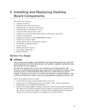
...configuration jumper • Clear passwords • Identify back panel connectors • Set up a log to record information about your system for Intel Matrix Storage Technology for using an antistatic wrist strap and a conductive foam pad. 2 Installing and Replacing Desktop Board Components This chapter tells... you how to: • Install the I/O shield • Install and remove the desktop board • Install and remove a processor and memory • Install and remove a PCI Express x16 card • Connect the IDE and Serial ATA cables • Configure your computer...
...configuration jumper • Clear passwords • Identify back panel connectors • Set up a log to record information about your system for Intel Matrix Storage Technology for using an antistatic wrist strap and a conductive foam pad. 2 Installing and Replacing Desktop Board Components This chapter tells... you how to: • Install the I/O shield • Install and remove the desktop board • Install and remove a processor and memory • Install and remove a PCI Express x16 card • Connect the IDE and Serial ATA cables • Configure your computer...

Product Guide
Page 26
... testing and are not Class B EMC compliant before integration, then EMC testing is required on the chassis • Hot components (like processors, voltage regulators, and heat sinks) • Damage to wires that could be careful of: • Sharp pins on connectors •... printed circuit assemblies • Rough edges and sharp corners on a representative sample of the newly completed computer. 26 Intel Desktop Board D925XCV/D925XBC Product Guide Installation Precautions When you to refer computer servicing to qualified technical personnel. If the instructions for associated ...
... testing and are not Class B EMC compliant before integration, then EMC testing is required on the chassis • Hot components (like processors, voltage regulators, and heat sinks) • Damage to wires that could be careful of: • Sharp pins on connectors •... printed circuit assemblies • Rough edges and sharp corners on a representative sample of the newly completed computer. 26 Intel Desktop Board D925XCV/D925XBC Product Guide Installation Precautions When you to refer computer servicing to qualified technical personnel. If the instructions for associated ...

Product Guide
Page 30
... the power cord from the socket (see Figure 6, A and B). Lift the load plate. Installing a Processor CAUTION Before installing or removing the processor, make sure that AC power has been removed by pushing the lever down and away from the computer; ... on how to install the processor to do so could damage the processor and the board. To install a processor, follow these instructions: 1. Lift Socket Lever 3. Lift the Load Plate and Don't Touch the Socket Contacts 30 Intel Desktop Board D925XCV/D925XBC Product Guide Installing and Removing a Processor Instructions on page 25. 2....
... the power cord from the socket (see Figure 6, A and B). Lift the load plate. Installing a Processor CAUTION Before installing or removing the processor, make sure that AC power has been removed by pushing the lever down and away from the computer; ... on how to install the processor to do so could damage the processor and the board. To install a processor, follow these instructions: 1. Lift Socket Lever 3. Lift the Load Plate and Don't Touch the Socket Contacts 30 Intel Desktop Board D925XCV/D925XBC Product Guide Installing and Removing a Processor Instructions on page 25. 2....

Product Guide
Page 31
... protective socket cover. Remove the Protective Socket Cover 5. E Figure 8. Do not discard the protective processor cover. Always replace the processor cover if the processor is removed from the socket (see Figure 9). Remove the processor from the socket (see Figure 8, E). Hold the processor only at the edges, being careful not to touch the bottom of the...
... protective socket cover. Remove the Protective Socket Cover 5. E Figure 8. Do not discard the protective processor cover. Always replace the processor cover if the processor is removed from the socket (see Figure 9). Remove the processor from the socket (see Figure 8, E). Hold the processor only at the edges, being careful not to touch the bottom of the...

Product Guide
Page 32
.... Align notches (see (Figure 10, H). Install Processor 7. Close the Load Plate Installing the Processor Fan Heat Sink Desktop Board D925XCV/D925XBC has an integrated processor fan heat sink retention mechanism (RM). Pressing down without tilting or sliding the processor in Figure 10. Intel Desktop Board D925XCV/D925XBC Product Guide 6. Hold the processor with the socket see Figure 10...
.... Align notches (see (Figure 10, H). Install Processor 7. Close the Load Plate Installing the Processor Fan Heat Sink Desktop Board D925XCV/D925XBC has an integrated processor fan heat sink retention mechanism (RM). Pressing down without tilting or sliding the processor in Figure 10. Intel Desktop Board D925XCV/D925XBC Product Guide 6. Hold the processor with the socket see Figure 10...

Product Guide
Page 33
Installing and Replacing Desktop Board Components Connecting the Processor Fan Heat Sink Cable Connect the processor fan heat sink cable to the processor installation manual or the Intel World Wide Web site at: http://support.intel.com/support/processors/pentium4/intnotes478.htm 33 OM16925 Figure 12. Connecting the Processor Fan Heat Sink Cable to the Processor Fan Header Removing the Processor For instruction on how to remove the processor fan heat sink and processor, refer to the 4-pin processor fan header (see Figure 12).
Installing and Replacing Desktop Board Components Connecting the Processor Fan Heat Sink Cable Connect the processor fan heat sink cable to the processor installation manual or the Intel World Wide Web site at: http://support.intel.com/support/processors/pentium4/intnotes478.htm 33 OM16925 Figure 12. Connecting the Processor Fan Heat Sink Cable to the Processor Fan Header Removing the Processor For instruction on how to remove the processor fan heat sink and processor, refer to the 4-pin processor fan header (see Figure 12).

Product Guide
Page 48
Location of Fan Headers OM16941 48 Connect chassis fan cables to the 4-pin processor fan header on the board. Connect the processor's fan heat sink cable to the board fan headers. 3 21 A 3 21 B 43 2 1 A 43 2 1 B Figure 24. Intel Desktop Board D925XCV/D925XBC Product Guide Connecting Fans Connecting Fans See Figure 24 for fan header locations.
Location of Fan Headers OM16941 48 Connect chassis fan cables to the 4-pin processor fan header on the board. Connect the processor's fan heat sink cable to the board fan headers. 3 21 A 3 21 B 43 2 1 A 43 2 1 B Figure 24. Intel Desktop Board D925XCV/D925XBC Product Guide Connecting Fans Connecting Fans See Figure 24 for fan header locations.

Product Guide
Page 50
... voltage power supply cable to the 1x4 connector. 3. Intel Desktop Board D925XCV/D925XBC Product Guide Connecting Power Cables NOTE Failure to use an ATX12V power supply, or not connecting the 12 V processor core voltage power supply connector (2x2) to the desktop board may result in "Before You Begin" on the desktop board is...
... voltage power supply cable to the 1x4 connector. 3. Intel Desktop Board D925XCV/D925XBC Product Guide Connecting Power Cables NOTE Failure to use an ATX12V power supply, or not connecting the 12 V processor core voltage power supply connector (2x2) to the desktop board may result in "Before You Begin" on the desktop board is...

Product Guide
Page 51
Connect the 12 V processor core voltage power supply cable to the 2x12 connector. 51 Observe the precautions in "Before You Begin" on page 25. 2. Installing and Replacing Desktop Board Components Connecting 2x12 Power Supply Cables If you have a 2x12 power supply, follow the instruction below. Connect the main power supply cable to the 2x2 connector. 3. Figure 26 shows the location of the power connectors for a 2x12 power supply. 1 2 Figure 27. Connecting 2x12 Power Supply Cables OM16950 1.
Connect the 12 V processor core voltage power supply cable to the 2x12 connector. 51 Observe the precautions in "Before You Begin" on page 25. 2. Installing and Replacing Desktop Board Components Connecting 2x12 Power Supply Cables If you have a 2x12 power supply, follow the instruction below. Connect the main power supply cable to the 2x2 connector. 3. Figure 26 shows the location of the power connectors for a 2x12 power supply. 1 2 Figure 27. Connecting 2x12 Power Supply Cables OM16950 1.


