

D915GLVG Technical Product Specification
Page 6
Intel Desktop Board D915GLVG Technical Product Specification 2.7 PCI Conventional Interrupt Routing Map 45 2.8 Connectors...46 2.8.1 Back Panel Connectors 47 2.8.2 Component-side Connectors 48 2.8.3 Front Panel USB Connectors ...PCI IDE Support 70 3.4 System Management BIOS (SMBIOS 71 3.5 Legacy USB Support...71 3.6 BIOS Updates ...72 3.6.1 Language Support 72 3.6.2 Custom Splash Screen 72 3.7 Boot Options ...73 3.7.1 CD-ROM Boot 73 3.7.2 Network Boot 73 3.7.3 Booting Without Attached Devices 73 3.7.4 Changing the Default Boot Device During POST 73 3.8 Fast Booting Systems with Intel...
Intel Desktop Board D915GLVG Technical Product Specification 2.7 PCI Conventional Interrupt Routing Map 45 2.8 Connectors...46 2.8.1 Back Panel Connectors 47 2.8.2 Component-side Connectors 48 2.8.3 Front Panel USB Connectors ...PCI IDE Support 70 3.4 System Management BIOS (SMBIOS 71 3.5 Legacy USB Support...71 3.6 BIOS Updates ...72 3.6.1 Language Support 72 3.6.2 Custom Splash Screen 72 3.7 Boot Options ...73 3.7.1 CD-ROM Boot 73 3.7.2 Network Boot 73 3.7.3 Booting Without Attached Devices 73 3.7.4 Changing the Default Boot Device During POST 73 3.8 Fast Booting Systems with Intel...

D915GLVG Technical Product Specification
Page 7
...61 Tables 1. Supported Memory Configurations 17 5. LAN Connector LED States 30 6. System Memory Map 41 10. Interrupts ...44 14. PCI Interrupt Routing Map 45 vii Block Diagram...14 3. Front/Back Panel Audio Connector Options for Front Panel USB Connectors 54 19. ...Connection Diagram for High Definition Audio Subsystem...... 28 10. DMA Channels ...41 11. PCI Configuration Space Map 43 13. Location of Thermal Sensors and Fan Connectors 31 13. Wake-up Devices and Events 35 9. Single Channel (Asymmetric) Mode Configuration with Three DIMMs 19 6. ...
...61 Tables 1. Supported Memory Configurations 17 5. LAN Connector LED States 30 6. System Memory Map 41 10. Interrupts ...44 14. PCI Interrupt Routing Map 45 vii Block Diagram...14 3. Front/Back Panel Audio Connector Options for Front Panel USB Connectors 54 19. ...Connection Diagram for High Definition Audio Subsystem...... 28 10. DMA Channels ...41 11. PCI Configuration Space Map 43 13. Location of Thermal Sensors and Fan Connectors 31 13. Wake-up Devices and Events 35 9. Single Channel (Asymmetric) Mode Configuration with Three DIMMs 19 6. ...

D915GLVG Technical Product Specification
Page 11
...* x1 bus add-in card connector Instantly Available PC Technology • Support for PCI Local Bus Specification Revision 2.2 • Support for PCI Express Revision 1.0a • Suspend to RAM support • Wake on PCI, RS-232, front panel, PS/2 devices, and USB ports Hardware Monitor Subsystem • Hardware monitoring and fan control ASIC •... fan connectors • Three fan sense inputs used to monitor fan activity • Fan speed control For information about Available configurations for the Desktop Board D915GLVG Refer to Section 1.2, page 15 11
...* x1 bus add-in card connector Instantly Available PC Technology • Support for PCI Local Bus Specification Revision 2.2 • Support for PCI Express Revision 1.0a • Suspend to RAM support • Wake on PCI, RS-232, front panel, PS/2 devices, and USB ports Hardware Monitor Subsystem • Hardware monitoring and fan control ASIC •... fan connectors • Three fan sense inputs used to monitor fan activity • Fan speed control For information about Available configurations for the Desktop Board D915GLVG Refer to Section 1.2, page 15 11

D915GLVG Technical Product Specification
Page 13
...codec B Front panel audio connector C PCI Conventional bus add-in card connectors D Ethernet PLC device E Rear chassis fan connector F Back panel connectors G +12V power connector (ATX12V) H LGA775 processor socket I Hardware monitoring and fan control ASIC J Processor fan connector K Intel 82915GL GMCH L DIMM Channel A sockets... X Auxiliary front panel power LED connector Y Front panel connector Z Front panel USB connectors AA Intel 82801FB I/O Controller Hub (ICH6) BB Speaker CC PCI Express x1 bus add-in card connector Product Description 13 Table 2.
...codec B Front panel audio connector C PCI Conventional bus add-in card connectors D Ethernet PLC device E Rear chassis fan connector F Back panel connectors G +12V power connector (ATX12V) H LGA775 processor socket I Hardware monitoring and fan control ASIC J Processor fan connector K Intel 82915GL GMCH L DIMM Channel A sockets... X Auxiliary front panel power LED connector Y Front panel connector Z Front panel USB connectors AA Intel 82801FB I/O Controller Hub (ICH6) BB Speaker CC PCI Express x1 bus add-in card connector Product Description 13 Table 2.

D915GLVG Technical Product Specification
Page 22
... utilities Refer to http://developer.intel.com/ Chapter 2 1.5.1 Intel® GMA900 Graphics Controller The Intel GMA900 graphics controller features the following devices: • Intel 82915GL Graphics Memory Controller Hub (GMCH) with Direct Media Interface (DMI) interconnect • Intel 82801FB I/O Controller Hub (ICH6...paths. The ICH6 is a centralized controller for the system bus, the memory bus, the PCI Express bus, and the DMI interconnect. Intel Desktop Board D915GLVG Technical Product Specification 1.5 Intel® 915GL Chipset The Intel 915GL chipset consists of the BIOS.
... utilities Refer to http://developer.intel.com/ Chapter 2 1.5.1 Intel® GMA900 Graphics Controller The Intel GMA900 graphics controller features the following devices: • Intel 82915GL Graphics Memory Controller Hub (GMCH) with Direct Media Interface (DMI) interconnect • Intel 82801FB I/O Controller Hub (ICH6...paths. The ICH6 is a centralized controller for the system bus, the memory bus, the PCI Express bus, and the DMI interconnect. Intel Desktop Board D915GLVG Technical Product Specification 1.5 Intel® 915GL Chipset The Intel 915GL chipset consists of the BIOS.

D915GLVG Technical Product Specification
Page 24
...devices (such as a boot device by setting the BIOS Setup program's Boot menu to Ultra DMA and is similar to one of the following modes: • Programmed I /O and IRQ resources are faster timings and require a specialized cable to 66 MB/sec. In Native mode, standard PCI... ATA IDE interface. Intel Desktop Board D915GLVG Technical Product Specification 1.5.3 IDE Support The boards provides five IDE interface connectors: • One parallel ATA IDE connector that supports two devices • Four serial ATA IDE connectors that support one device per channel. For compatibility...
...devices (such as a boot device by setting the BIOS Setup program's Boot menu to Ultra DMA and is similar to one of the following modes: • Programmed I /O and IRQ resources are faster timings and require a specialized cable to 66 MB/sec. In Native mode, standard PCI... ATA IDE interface. Intel Desktop Board D915GLVG Technical Product Specification 1.5.3 IDE Support The boards provides five IDE interface connectors: • One parallel ATA IDE connector that supports two devices • Four serial ATA IDE connectors that support one device per channel. For compatibility...

D915GLVG Technical Product Specification
Page 29
...11. LAN Connector LED Locations 29 Product Description 1.9 LAN Subsystem The LAN subsystem consists of the following: • Physical layer interface device Intel® 82562GZ PLC for 10/100 Mbits/sec Ethernet LAN connectivity. • RJ-45 LAN connector with integrated status LEDs Additional ...features of the LAN subsystem include: • CSMA/CD protocol engine • LAN connect interface that supports the 82562GZ • PCI Conventional bus power management ⎯ Supports ACPI technology ⎯ Supports LAN wake capabilities 1.9.1 10/100 Mbits/sec LAN Subsystem The 10/...
...11. LAN Connector LED Locations 29 Product Description 1.9 LAN Subsystem The LAN subsystem consists of the following: • Physical layer interface device Intel® 82562GZ PLC for 10/100 Mbits/sec Ethernet LAN connectivity. • RJ-45 LAN connector with integrated status LEDs Additional ...features of the LAN subsystem include: • CSMA/CD protocol engine • LAN connect interface that supports the 82562GZ • PCI Conventional bus power management ⎯ Supports ACPI technology ⎯ Supports LAN wake capabilities 1.9.1 10/100 Mbits/sec LAN Subsystem The 10/...

D915GLVG Technical Product Specification
Page 37
...last known wake state. The boards support the PCI Bus Power Management Interface Specification. The use of providing adequate +5 V standby current. Table 8 on page 35 lists the devices and events that supports Wake from USB. 1.11.2.7 Wake from PS/2 Devices PS/2 device activity wakes the computer from an ACPI S1 ...PME# Signal Wake-up Support When the PME# signal on the PCI Conventional bus is asserted, the computer wakes from an ACPI S1, S3, S4, or S5 state. 37 While in BIOS). 1.11.2.9 WAKE# Signal Wake-up device or event, the system quickly returns to provide adequate standby current ...
...last known wake state. The boards support the PCI Bus Power Management Interface Specification. The use of providing adequate +5 V standby current. Table 8 on page 35 lists the devices and events that supports Wake from USB. 1.11.2.7 Wake from PS/2 Devices PS/2 device activity wakes the computer from an ACPI S1 ...PME# Signal Wake-up Support When the PME# signal on the PCI Conventional bus is asserted, the computer wakes from an ACPI S1, S3, S4, or S5 state. 37 While in BIOS). 1.11.2.9 WAKE# Signal Wake-up device or event, the system quickly returns to provide adequate standby current ...

D915GLVG Technical Product Specification
Page 43
... Space Map Table 12. PCI Configuration Space Map Bus Number (hex) 00 00 00 00 00 00 00 00 00 00 00 00 00 00 00 00 00 00 (Note) (Note) (Note) Device Number (hex) 00 02 02 1B 1C 1C 1C 1C 1D 1D 1D 1D 1D 1E 1F 1F 1F... 03 07 00 00 01 02 03 00 00 00 Description Memory controller of Intel 82915GL component Integrated graphics controller Integrated graphics controller Intel High Definition Audio Controller PCI Express port 1 (PCI Express x1 bus connector) PCI Express port 2 PCI Express port 3 PCI Express port 4 (not used) USB UHCI controller 1 USB UHCI controller 2 USB UHCI controller 3 USB...
... Space Map Table 12. PCI Configuration Space Map Bus Number (hex) 00 00 00 00 00 00 00 00 00 00 00 00 00 00 00 00 00 00 (Note) (Note) (Note) Device Number (hex) 00 02 02 1B 1C 1C 1C 1C 1D 1D 1D 1D 1D 1E 1F 1F 1F... 03 07 00 00 01 02 03 00 00 00 Description Memory controller of Intel 82915GL component Integrated graphics controller Integrated graphics controller Intel High Definition Audio Controller PCI Express port 1 (PCI Express x1 bus connector) PCI Express port 2 PCI Express port 3 PCI Express port 4 (not used) USB UHCI controller 1 USB UHCI controller 2 USB UHCI controller 3 USB...

D915GLVG Technical Product Specification
Page 45
... where maximum performance is classified as INTD. PCI Conventional devices are electrically tied together on add-in this category. All PCI Conventional interrupt sources either onboard or from a device, a PCI Conventional device should not share an interrupt with other PCI Conventional devices. PCI Interrupt Routing Map PCI Interrupt Source ICH6 LAN PCI bus connector 1 PCI bus connector 2 PIRQA PIRQB ICH6 PIRQ Signal...
... where maximum performance is classified as INTD. PCI Conventional devices are electrically tied together on add-in this category. All PCI Conventional interrupt sources either onboard or from a device, a PCI Conventional device should not share an interrupt with other PCI Conventional devices. PCI Interrupt Routing Map PCI Interrupt Source ICH6 LAN PCI bus connector 1 PCI bus connector 2 PIRQA PIRQB ICH6 PIRQ Signal...

D915GLVG Technical Product Specification
Page 70
... other system resources. Autoconfiguration lets a user insert or remove PCI cards without having to optimize capacity and performance. Any interrupts set to ATA-66/100 and recognizes any ATAPI compliant devices, including CD-ROM drives, tape drives, and Ultra DMA ...Organization The Firmware Hub (FWH) includes a 4 Mbit (512 KB) symmetrical flash memory device. 3.3 Resource Configuration 3.3.1 PCI Autoconfiguration The BIOS can automatically configure PCI devices. Table 36. Intel Desktop Board D915GLVG Technical Product Specification Table 36 lists the BIOS Setup program menu features.
... other system resources. Autoconfiguration lets a user insert or remove PCI cards without having to optimize capacity and performance. Any interrupts set to ATA-66/100 and recognizes any ATAPI compliant devices, including CD-ROM drives, tape drives, and Ultra DMA ...Organization The Firmware Hub (FWH) includes a 4 Mbit (512 KB) symmetrical flash memory device. 3.3 Resource Configuration 3.3.1 PCI Autoconfiguration The BIOS can automatically configure PCI devices. Table 36. Intel Desktop Board D915GLVG Technical Product Specification Table 36 lists the BIOS Setup program menu features.

D915GLVG Technical Product Specification
Page 79
...that code applies to be installed in F000 shadow RAM. Displaying the POST-codes requires a PCI bus add-in F000 shadow RAM. Table 41 defines the uncompressed INIT code checkpoints, Table ...operation. To check recovery mode and verify main BIOS checksum. EB Booting from floppy and ATAPI device failed. E9 Initialize floppy drive. Compressed recovery code is initialized. D6 Control is bad, go... to check point E0 for giving control to check point E9). 79 E8 Initialize extra (Intel Recovery) Module. D7 Find Main BIOS module in segment 0. Give two beeps. If either it...
...that code applies to be installed in F000 shadow RAM. Displaying the POST-codes requires a PCI bus add-in F000 shadow RAM. Table 41 defines the uncompressed INIT code checkpoints, Table ...operation. To check recovery mode and verify main BIOS checksum. EB Booting from floppy and ATAPI device failed. E9 Initialize floppy drive. Compressed recovery code is initialized. D6 Control is bad, go... to check point E0 for giving control to check point E9). 79 E8 Initialize extra (Intel Recovery) Module. D7 Find Main BIOS module in segment 0. Give two beeps. If either it...

D915GLVG Technical Product Specification
Page 84
... 84 Intel Desktop Board D915GLVG Technical Product Specification Table 46 describes the lower nibble of the high byte and indicates the bus on which the routines are several POST routines that external device. Table 46. Lower Nibble High Byte Functions Value Description 0 Generic DIM (Device Initialization Manager) 1 On-board System devices 2 ISA devices 3 EISA devices 4 ISA PnP devices 5 PCI devices...
... 84 Intel Desktop Board D915GLVG Technical Product Specification Table 46 describes the lower nibble of the high byte and indicates the bus on which the routines are several POST routines that external device. Table 46. Lower Nibble High Byte Functions Value Description 0 Generic DIM (Device Initialization Manager) 1 On-board System devices 2 ISA devices 3 EISA devices 4 ISA PnP devices 5 PCI devices...
Intel Desktop Board D915GLVG Product Guide
Page 9
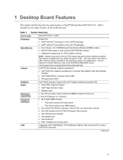
...of Intel® Desktop Board D915GLVG. Table 1. 1 Desktop Board Features This chapter briefly describes the main features of the desktop board. For the latest list of tested memory, refer to the Intel World Wide Web site at: http://support.intel.com/support/motherboards/desktop/ Intel&#... and mouse ports Integrated Intel® GD82562GZ 10/100 Mbit/sec Platform LAN Connect (PLC) device with Intel® Graphics Media Accelerator 900 • Intel 915GL Express Chipset • Intel® High Definition Audio • Realtek codec Expansion Capabilities • Two PCI bus add-in the ...
...of Intel® Desktop Board D915GLVG. Table 1. 1 Desktop Board Features This chapter briefly describes the main features of the desktop board. For the latest list of tested memory, refer to the Intel World Wide Web site at: http://support.intel.com/support/motherboards/desktop/ Intel&#... and mouse ports Integrated Intel® GD82562GZ 10/100 Mbit/sec Platform LAN Connect (PLC) device with Intel® Graphics Media Accelerator 900 • Intel 915GL Express Chipset • Intel® High Definition Audio • Realtek codec Expansion Capabilities • Two PCI bus add-in the ...

Intel Desktop Board D915GLVG Product Guide
Page 10
...• Support for SMBIOS • Intel® Rapid BIOS Boot • Intel® Express BIOS Update Power Management • Support for Advanced Configuration and Power Interface (ACPI) • Suspend to RAM (STR) • Wake on USB, PCI, PCI Express, PS/2, LAN, and front panel... to detect out of range values Related Links: For more information about Intel Desktop Board D915GLVG, including the Technical Product Specification (TPS), BIOS updates, and device drivers, go to: http://support.intel.com/support/motherboards/desktop/ Supported Operating Systems The desktop board supports the ...
...• Support for SMBIOS • Intel® Rapid BIOS Boot • Intel® Express BIOS Update Power Management • Support for Advanced Configuration and Power Interface (ACPI) • Suspend to RAM (STR) • Wake on USB, PCI, PCI Express, PS/2, LAN, and front panel... to detect out of range values Related Links: For more information about Intel Desktop Board D915GLVG, including the Technical Product Specification (TPS), BIOS updates, and device drivers, go to: http://support.intel.com/support/motherboards/desktop/ Supported Operating Systems The desktop board supports the ...

Intel Desktop Board D915GLVG Product Guide
Page 18
.... Expandability The desktop board supports the following: • One PCI Express x1 add-in card • Two PCI add-in your computer. Intel Desktop Board D915GLVG Product Guide Enhanced IDE Interface The ICH6's IDE interface handles the exchange of information between the processor and peripheral devices like hard disks, CD-ROM drives, and Iomega Zip...
.... Expandability The desktop board supports the following: • One PCI Express x1 add-in card • Two PCI add-in your computer. Intel Desktop Board D915GLVG Product Guide Enhanced IDE Interface The ICH6's IDE interface handles the exchange of information between the processor and peripheral devices like hard disks, CD-ROM drives, and Iomega Zip...

Intel Desktop Board D915GLVG Product Guide
Page 20
...support the standard Instantly Available (ACPI S3 sleep state) configuration. When signaled by a wake-up device or event, the system quickly returns to -RAM) sleep state. It is recommended that processor ...desktop board's standby power indicator, shown in memory. This includes the memory modules and PCI bus connectors, even when the computer appears to provide adequate standby current when using the ...chassis fan header. See Figure 21 on the system temperature. Intel Desktop Board D915GLVG Product Guide Fan Connectors The desktop board has a 4-pin processor fan header and two ...
...support the standard Instantly Available (ACPI S3 sleep state) configuration. When signaled by a wake-up device or event, the system quickly returns to -RAM) sleep state. It is recommended that processor ...desktop board's standby power indicator, shown in memory. This includes the memory modules and PCI bus connectors, even when the computer appears to provide adequate standby current when using the ...chassis fan header. See Figure 21 on the system temperature. Intel Desktop Board D915GLVG Product Guide Fan Connectors The desktop board has a 4-pin processor fan header and two ...

Intel Desktop Board D915GLVG Product Guide
Page 34
Turn off all peripheral devices connected to the computer. Installing a DIMM OM17370 4. Insert the bottom edge of the DIMM with the memory retention mechanism. 1. Replace the computer's cover and reconnect ... 0 DIMM 1 Figure 16. Make sure the clips at the bottom edge of the DIMM into place. Intel Desktop Board D915GLVG Product Guide Installing DIMMs CAUTION Install memory in the DIMM sockets prior to installing the PCI Express video card to the open position. 5. Turn off the computer and disconnect the AC power cord...
Turn off all peripheral devices connected to the computer. Installing a DIMM OM17370 4. Insert the bottom edge of the DIMM with the memory retention mechanism. 1. Replace the computer's cover and reconnect ... 0 DIMM 1 Figure 16. Make sure the clips at the bottom edge of the DIMM into place. Intel Desktop Board D915GLVG Product Guide Installing DIMMs CAUTION Install memory in the DIMM sockets prior to installing the PCI Express video card to the open position. 5. Turn off the computer and disconnect the AC power cord...

