
Product Guide
Page 4
Intel Desktop Boards D850EMD2 and D850EMV2 Product Guide 3 Updating the BIOS Updating the BIOS with the Intel® Express BIOS Update Utility 35 Updating the BIOS with the Intel® Flash Memory Update Utility 35 Obtaining the BIOS Update File 35 Updating the BIOS...36 Recovering the BIOS 36 4...Audio Connectors 59 Power and Hardware Connectors 60 Add-In Card and Peripheral Interface Connectors 62 Front Panel Connectors 64 Desktop Board Resources 65 Memory Map ...65 DMA Channels ...65 I/O Map ...66 Interrupts ...68 A Error Messages and Indicators BIOS Beep Codes ...69 BIOS Error ...
Intel Desktop Boards D850EMD2 and D850EMV2 Product Guide 3 Updating the BIOS Updating the BIOS with the Intel® Express BIOS Update Utility 35 Updating the BIOS with the Intel® Flash Memory Update Utility 35 Obtaining the BIOS Update File 35 Updating the BIOS...36 Recovering the BIOS 36 4...Audio Connectors 59 Power and Hardware Connectors 60 Add-In Card and Peripheral Interface Connectors 62 Front Panel Connectors 64 Desktop Board Resources 65 Memory Map ...65 DMA Channels ...65 I/O Map ...66 Interrupts ...68 A Error Messages and Indicators BIOS Beep Codes ...69 BIOS Error ...
Product Guide
Page 5
...of the BIOS Configuration Jumper 30 15. Installing the I/O Shield ...22 5. Location of the Standby Power Indicator 18 4. Desktop Board D850EMV2 Power and Hardware Control Connectors 61 20. Feature Summary ...7 2. Jumper Settings for Intended Applications 77 Figures 1. Maintenance Menu ...40 9. ... Interface Connectors 63 22. Processors Supported by the Desktop Boards 11 3. Standby Current Requirements 19 5. Desktop Board D850EMD2 Components 9 2. Installing a Memory Module 27 12. RIMM Installation ...26 11. Removing the AGP Card...28 13. BIOS Setup Program Menu Bar...
...of the BIOS Configuration Jumper 30 15. Installing the I/O Shield ...22 5. Location of the Standby Power Indicator 18 4. Desktop Board D850EMV2 Power and Hardware Control Connectors 61 20. Feature Summary ...7 2. Jumper Settings for Intended Applications 77 Figures 1. Maintenance Menu ...40 9. ... Interface Connectors 63 22. Processors Supported by the Desktop Boards 11 3. Standby Current Requirements 19 5. Desktop Board D850EMD2 Components 9 2. Installing a Memory Module 27 12. RIMM Installation ...26 11. Removing the AGP Card...28 13. BIOS Setup Program Menu Bar...
Product Guide
Page 7
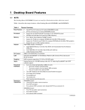
...USB connector One port routed to 2 GB of system memory Intel® 850E chipset, consisting of the Desktop Boards D850EMD2 and D850EMV2. Table 1. 1 Desktop Board Features ✏ NOTE The Desktop Board D850EMD2 layout was used for up to the optional CNR • ... Support for illustrations unless otherwise noted. Feature Summary Form Factors Processor Memory Chipset • microATX at 9.6 inches by 9.6 inches (D850EMD2 board) • ATX at 9.6 inches by 12 inches (D850EMV2 board) • Support for an Intel® Pentium® 4 processor in card connectors • One...
...USB connector One port routed to 2 GB of system memory Intel® 850E chipset, consisting of the Desktop Boards D850EMD2 and D850EMV2. Table 1. 1 Desktop Board Features ✏ NOTE The Desktop Board D850EMD2 layout was used for up to the optional CNR • ... Support for illustrations unless otherwise noted. Feature Summary Form Factors Processor Memory Chipset • microATX at 9.6 inches by 9.6 inches (D850EMD2 board) • ATX at 9.6 inches by 12 inches (D850EMV2 board) • Support for an Intel® Pentium® 4 processor in card connectors • One...
Product Guide
Page 8
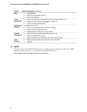
Feature Summary (continued) BIOS • Intel/AMI BIOS • 4 Mbit symmetrical flash memory • Support for SMBIOS Power Management • Support for Advanced Configuration and Power Interface (ACPI 1.0) • Support for Advanced Power... for the front panel • Speaker ✏ NOTE For information about Intel® desktop boards, including technical product specifications, BIOS updates, and device drivers, go to the Intel World Wide Web site at: http://support.intel.com/support/motherboards/desktop 8 Intel Desktop Boards D850EMD2 and D850EMV2 Product Guide Table 1.
Feature Summary (continued) BIOS • Intel/AMI BIOS • 4 Mbit symmetrical flash memory • Support for SMBIOS Power Management • Support for Advanced Configuration and Power Interface (ACPI 1.0) • Support for Advanced Power... for the front panel • Speaker ✏ NOTE For information about Intel® desktop boards, including technical product specifications, BIOS updates, and device drivers, go to the Intel World Wide Web site at: http://support.intel.com/support/motherboards/desktop 8 Intel Desktop Boards D850EMD2 and D850EMV2 Product Guide Table 1.

Product Guide
Page 10
... voltage connector X BIOS configuration jumper I Processor fan connector (CPU fan) (tachometer input) Y SCSI hard drive activity LED connector J Intel 82850E Memory Controller Hub (MCH) Z Intel 82801BA I/O Controller Hub (ICH2) K Processor socket AA NEC D720100AGM USB 2.0 controller L RIMM sockets BB PCI bus add-in card ...Riser (CNR) (optional) N Power connector DD Chassis fan connector (fan 3) O Floppy drive connector P Primary IDE connector Figure 2. Intel Desktop Boards D850EMD2 and D850EMV2 Product Guide Figure 2 shows the location of the major components on the Desktop Board...
... voltage connector X BIOS configuration jumper I Processor fan connector (CPU fan) (tachometer input) Y SCSI hard drive activity LED connector J Intel 82850E Memory Controller Hub (MCH) Z Intel 82801BA I/O Controller Hub (ICH2) K Processor socket AA NEC D720100AGM USB 2.0 controller L RIMM sockets BB PCI bus add-in card ...Riser (CNR) (optional) N Power connector DD Chassis fan connector (fan 3) O Floppy drive connector P Primary IDE connector Figure 2. Intel Desktop Boards D850EMD2 and D850EMV2 Product Guide Figure 2 shows the location of the major components on the Desktop Board...

Product Guide
Page 12
... but (FSB) operation • Support for a single AGP device 12 Intel Desktop Boards D850EMD2 and D850EMV2 Product Guide Main Memory The desktop boards have four 2.5 V memory module sockets that support these memory requirements, refer to the Desktop Board D850EMD2 or D850EMV2 link on this Intel World Wide Web site: http://support.intel.com/support/motherboards/desktop For information about installing...
... but (FSB) operation • Support for a single AGP device 12 Intel Desktop Boards D850EMD2 and D850EMV2 Product Guide Main Memory The desktop boards have four 2.5 V memory module sockets that support these memory requirements, refer to the Desktop Board D850EMD2 or D850EMV2 link on this Intel World Wide Web site: http://support.intel.com/support/motherboards/desktop For information about installing...
Product Guide
Page 16
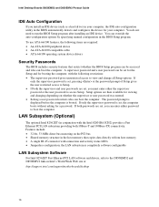
... detects and configures the device for a password. You do not need to /from host memory • A single RJ-45 connector with the Intel 82801BA ICH2) provides a Fast Ethernet PCI LAN subsystem providing both 10Base-T and 100Base-TX connectivity...memory structure in the host memory that restrict whether the BIOS Setup program can be accessed and who can be set , you can override the auto-configuration options by specifying manual configuration in the BIOS Setup program. A supervisor password and a user password can boot the computer. Intel Desktop Boards D850EMD2 and D850EMV2...
... detects and configures the device for a password. You do not need to /from host memory • A single RJ-45 connector with the Intel 82801BA ICH2) provides a Fast Ethernet PCI LAN subsystem providing both 10Base-T and 100Base-TX connectivity...memory structure in the host memory that restrict whether the BIOS Setup program can be accessed and who can be set , you can override the auto-configuration options by specifying manual configuration in the BIOS Setup program. A supervisor password and a user password can boot the computer. Intel Desktop Boards D850EMD2 and D850EMV2...

Product Guide
Page 18
...Instantly Available technology enables the desktop board to enter the ACPI S3 (Suspend-to its last known awake state. While in memory. Actual measurements may lose register settings stored in the S3 sleep state, the computer will appear to be off . CAUTION ...the system quickly returns to -RAM) sleep state. This includes the memory modules and PCI bus connectors even when the computer appears to be off . Values are determined by the LED turning amber. Intel Desktop Boards D850EMD2 and D850EMV2 Product Guide Instantly Available Technology CAUTION For Instantly Available technology, the 5 ...
...Instantly Available technology enables the desktop board to enter the ACPI S3 (Suspend-to its last known awake state. While in memory. Actual measurements may lose register settings stored in the S3 sleep state, the computer will appear to be off . CAUTION ...the system quickly returns to -RAM) sleep state. This includes the memory modules and PCI bus connectors even when the computer appears to be off . Values are determined by the LED turning amber. Intel Desktop Boards D850EMD2 and D850EMV2 Product Guide Instantly Available Technology CAUTION For Instantly Available technology, the 5 ...
Product Guide
Page 25
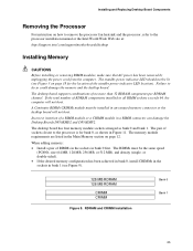
...256 MB, or 512 MB), and density (single- Failure to the processor installation manual or the Intel World Wide Web site at: http://support.intel.com/support/motherboards/desktop Installing Memory CAUTIONS Before installing or removing RIMM modules, make sure that AC power has been removed by unplugging...remove the processor fan heatsink and the processor, refer to do so could damage the memory and the desktop board. The RIMMs must be installed in a RIMM connector can damage the Desktop Boards D850EMD2 and D850EMV2. A Continuity RIMM (CRIMM) module must be lit (see Figure 9). 128 MB ...
...256 MB, or 512 MB), and density (single- Failure to the processor installation manual or the Intel World Wide Web site at: http://support.intel.com/support/motherboards/desktop Installing Memory CAUTIONS Before installing or removing RIMM modules, make sure that AC power has been removed by unplugging...remove the processor fan heatsink and the processor, refer to do so could damage the memory and the desktop board. The RIMMs must be installed in a RIMM connector can damage the Desktop Boards D850EMD2 and D850EMV2. A Continuity RIMM (CRIMM) module must be lit (see Figure 9). 128 MB ...
Product Guide
Page 26
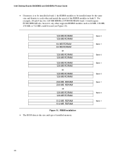
... 64 MB, 128 MB, 256 MB, or 512 MB could be the same size and density to each other and match the speed of installed memory. Intel Desktop Boards D850EMD2 and D850EMV2 Product Guide • If memory is to be installed in bank 0.
... 64 MB, 128 MB, 256 MB, or 512 MB could be the same size and density to each other and match the speed of installed memory. Intel Desktop Boards D850EMD2 and D850EMV2 Product Guide • If memory is to be installed in bank 0.
Product Guide
Page 32
Intel Desktop Boards D850EMD2 and D850EMV2 Product Guide Replacing the Battery A coin-cell battery (CR2032) powers the real-time clock and CMOS memory. Figure 15 on mahdollista. Les piles usagées doivent être recyclées dans la mesure du possible. Brukte batterier bør kastes i henhold ...
Intel Desktop Boards D850EMD2 and D850EMV2 Product Guide Replacing the Battery A coin-cell battery (CR2032) powers the real-time clock and CMOS memory. Figure 15 on mahdollista. Les piles usagées doivent être recyclées dans la mesure du possible. Brukte batterier bør kastes i henhold ...

Product Guide
Page 35
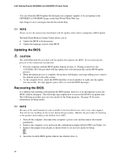
... utility or the Intel® Flash Memory Update Utility, and how to recover the BIOS if an update fails. To update the BIOS with the Intel® Express BIOS Update Utility With the Intel Express BIOS Update utility you need to a new version of Windows-based installation wizards. Go to the D850EMV2 or D850EMD2 page and...
... utility or the Intel® Flash Memory Update Utility, and how to recover the BIOS if an update fails. To update the BIOS with the Intel® Express BIOS Update Utility With the Intel Express BIOS Update utility you need to a new version of Windows-based installation wizards. Go to the D850EMV2 or D850EMD2 page and...
Product Guide
Page 36
... appears, press to make sure the update was successful. You will display a message telling you to: • Update the BIOS in flash memory • Update the language section of code available in drive A. Recovering the BIOS It is unlikely that anything on Setup modes. ✏ NOTE...the computer cover and locate the configuration jumper labeled J9H2 (see anything will automatically run the BIOS update process. 2. Intel Desktop Boards D850EMD2 and D850EMV2 Product Guide You can obtain the BIOS update file through your computer supplier or by listening to the speaker and looking ...
... appears, press to make sure the update was successful. You will display a message telling you to: • Update the BIOS in flash memory • Update the language section of code available in drive A. Recovering the BIOS It is unlikely that anything on Setup modes. ✏ NOTE...the computer cover and locate the configuration jumper labeled J9H2 (see anything will automatically run the BIOS update process. 2. Intel Desktop Boards D850EMD2 and D850EMV2 Product Guide You can obtain the BIOS update file through your computer supplier or by listening to the speaker and looking ...

Product Guide
Page 39
... key after the Power-On Self-Test (POST) memory test begins and before the operating system boot begins. ✏ NOTE The BIOS Setup menus described in this section apply to the Intel Desktop Board D850EMD2/D850EMV2 Technical Product Specification or the Intel World Wide Web site: http://support.intel.com/support/motherboards/desktop ✏ NOTE For...
... key after the Power-On Self-Test (POST) memory test begins and before the operating system boot begins. ✏ NOTE The BIOS Setup menus described in this section apply to the Intel Desktop Board D850EMD2/D850EMV2 Technical Product Specification or the Intel World Wide Web site: http://support.intel.com/support/motherboards/desktop ✏ NOTE For...
Product Guide
Page 42
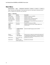
... Description Displays the version of second-level cache and whether it is ECC-capable. Allows the user to non-ECC. If non-ECC memory is used by the BIOS. Table 10. Displays processor type. Displays the size of the BIOS. Displays the total amount of RAM ...is installed, BIOS will detect and change setting to enable error reporting if the system and all installed memory supports ECC. Specifies the current date. 42 Intel Desktop Boards D850EMD2 and D850EMV2 Product Guide Main Menu Maintenance Main Advanced Security Power Boot Exit Table 10 describes the Main Menu. ...
... Description Displays the version of second-level cache and whether it is ECC-capable. Allows the user to non-ECC. If non-ECC memory is used by the BIOS. Table 10. Displays processor type. Displays the size of the BIOS. Displays the total amount of RAM ...is installed, BIOS will detect and change setting to enable error reporting if the system and all installed memory supports ECC. Specifies the current date. 42 Intel Desktop Boards D850EMD2 and D850EMV2 Product Guide Main Menu Maintenance Main Advanced Security Power Boot Exit Table 10 describes the Main Menu. ...

Product Guide
Page 56
... saves the changes made in the BIOS Setup program. Load Setup Defaults Loads the factory default values for Setup options. Intel Desktop Boards D850EMD2 and D850EMV2 Product Guide Exit Menu Maintenance Main Advanced Security Power Boot Exit The menu shown in Table 26 is corrupted, the BIOS... reads the custom defaults. Normally, the BIOS reads the Setup values from flash memory. If no custom defaults are used to exit ...
... saves the changes made in the BIOS Setup program. Load Setup Defaults Loads the factory default values for Setup options. Intel Desktop Boards D850EMD2 and D850EMV2 Product Guide Exit Menu Maintenance Main Advanced Security Power Boot Exit The menu shown in Table 26 is corrupted, the BIOS... reads the custom defaults. Normally, the BIOS reads the Setup values from flash memory. If no custom defaults are used to exit ...
Product Guide
Page 69
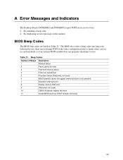
...D850EMD2 and D850EMV2 report POST errors in two ways: • By sounding a beep code • By displaying an error message on the monitor BIOS Beep Codes The BIOS beep codes are listed in Table 31. Table 31. Beep Codes Number of Beeps 1 2 3 4 5 6 7 8 9 10 11 Description Refresh failure Parity cannot be toggled (memory... failure or not present) Exception interrupt error Display memory R/W error (Reserved; not used ) CMOS Shutdown register test error Invalid BIOS (such as, POST module not found...
...D850EMD2 and D850EMV2 report POST errors in two ways: • By sounding a beep code • By displaying an error message on the monitor BIOS Beep Codes The BIOS beep codes are listed in Table 31. Table 31. Beep Codes Number of Beeps 1 2 3 4 5 6 7 8 9 10 11 Description Refresh failure Parity cannot be toggled (memory... failure or not present) Exception interrupt error Display memory R/W error (Reserved; not used ) CMOS Shutdown register test error Invalid BIOS (such as, POST module not found...
Product Guide
Page 70
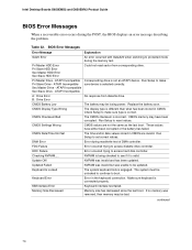
... correctly. Run Setup to reset values. NVRAM was unable to protected mode during read sector from diskette drive. If no memory was removed, then memory may have either been corrupted or the battery has failed. Pri Master HDD Error Pri Slave HDD Error Sec Master HDD... controller. NVRAM is being checked to make sure type is valid. CMOS Checksum Bad The CMOS checksum is connected properly. Intel Desktop Boards D850EMD2 and D850EMV2 Product Guide BIOS Error Messages When a recoverable error occurs during the POST, the BIOS displays an error message describing the problem...
... correctly. Run Setup to reset values. NVRAM was unable to protected mode during read sector from diskette drive. If no memory was removed, then memory may have either been corrupted or the battery has failed. Pri Master HDD Error Pri Slave HDD Error Sec Master HDD... controller. NVRAM is being checked to make sure type is valid. CMOS Checksum Bad The CMOS checksum is connected properly. Intel Desktop Boards D850EMD2 and D850EMV2 Product Guide BIOS Error Messages When a recoverable error occurs during the POST, the BIOS displays an error message describing the problem...

Product Specification
Page 6
Intel Desktop Board D850EMD2/D850EMV2 Technical Product Specification 2 Technical Reference 2.1 Introduction...47 2.2 Memory Map ...47 2.3 Fixed I/O Map...48 2.4 DMA Channels ...49 2.5 PCI Configuration Space Map 49 2.6 Interrupts ...50 2.7 PCI Interrupt Routing Map 51 ... Front Panel Audio Connector/Jumper Block 74 2.9.2 BIOS Setup Configuration Jumper Block 75 2.10 Mechanical Considerations 76 2.10.1 Desktop Board D850EMD2 Form Factor 76 2.10.2 Desktop Board D850EMV2 Form Factor 77 2.10.3 I/O Shield ...78 2.11 Electrical Considerations 79 2.11.1 Power Consumption 79 2.11.2 Add-in Board...
Intel Desktop Board D850EMD2/D850EMV2 Technical Product Specification 2 Technical Reference 2.1 Introduction...47 2.2 Memory Map ...47 2.3 Fixed I/O Map...48 2.4 DMA Channels ...49 2.5 PCI Configuration Space Map 49 2.6 Interrupts ...50 2.7 PCI Interrupt Routing Map 51 ... Front Panel Audio Connector/Jumper Block 74 2.9.2 BIOS Setup Configuration Jumper Block 75 2.10 Mechanical Considerations 76 2.10.1 Desktop Board D850EMD2 Form Factor 76 2.10.2 Desktop Board D850EMV2 Form Factor 77 2.10.3 I/O Shield ...78 2.11 Electrical Considerations 79 2.11.1 Power Consumption 79 2.11.2 Add-in Board...

Product Specification
Page 8
.... Intel Desktop Board D850EMD2/D850EMV2 Technical Product Specification Figures 1. Desktop Board D850EMD2 Dimensions 76 20. Manufacturing Options 13 4. Desktop Board D850EMD2 Components... 14 2. PCI Interrupt Routing Map 52 viii Summary of Pressing the Power Switch 39 11. Desktop Board D850EMV2 Components 15 3. Thermal Monitoring...38 11. System Memory Map 47 16. ICH2 and CNR Signal Interface 35 10. Memory...
.... Intel Desktop Board D850EMD2/D850EMV2 Technical Product Specification Figures 1. Desktop Board D850EMD2 Dimensions 76 20. Manufacturing Options 13 4. Desktop Board D850EMD2 Components... 14 2. PCI Interrupt Routing Map 52 viii Summary of Pressing the Power Switch 39 11. Desktop Board D850EMV2 Components 15 3. Thermal Monitoring...38 11. System Memory Map 47 16. ICH2 and CNR Signal Interface 35 10. Memory...


