

Product Guide
Page 3
Contents 1 Desktop Board Features Desktop Board Components 9 Processor ...11 Main Memory ...12 Intel® 850E Chipset ...12 Intel® 82850E Memory Controller Hub (MCH 12 Intel® 82801BA I/O Controller Hub (ICH2 13 Firmware Hub (FWH 13 Input/Output (I/O) Controller 13 Real-Time Clock... the I/O Shield ...22 Installing and Removing the Desktop Board 22 Installing a Processor ...24 Removing the Processor ...25 Installing Memory ...25 Removing Memory ...27 Installing an AGP Card...28 Removing the AGP Card ...28 Connecting the IDE Cable 29 Setting the BIOS Configuration Jumper...
Contents 1 Desktop Board Features Desktop Board Components 9 Processor ...11 Main Memory ...12 Intel® 850E Chipset ...12 Intel® 82850E Memory Controller Hub (MCH 12 Intel® 82801BA I/O Controller Hub (ICH2 13 Firmware Hub (FWH 13 Input/Output (I/O) Controller 13 Real-Time Clock... the I/O Shield ...22 Installing and Removing the Desktop Board 22 Installing a Processor ...24 Removing the Processor ...25 Installing Memory ...25 Removing Memory ...27 Installing an AGP Card...28 Removing the AGP Card ...28 Connecting the IDE Cable 29 Setting the BIOS Configuration Jumper...
Product Guide
Page 4
Intel Desktop Boards D850EMD2 and D850EMV2 Product Guide 3 Updating the BIOS Updating the BIOS with the Intel® Express BIOS Update Utility 35 Updating the BIOS with the Intel® Flash Memory Update Utility 35 Obtaining the BIOS Update File 35 Updating the BIOS...36 Recovering the BIOS 36...Audio Connectors 59 Power and Hardware Connectors 60 Add-In Card and Peripheral Interface Connectors 62 Front Panel Connectors 64 Desktop Board Resources 65 Memory Map ...65 DMA Channels ...65 I/O Map ...66 Interrupts ...68 A Error Messages and Indicators BIOS Beep Codes ...69 BIOS Error ...
Intel Desktop Boards D850EMD2 and D850EMV2 Product Guide 3 Updating the BIOS Updating the BIOS with the Intel® Express BIOS Update Utility 35 Updating the BIOS with the Intel® Flash Memory Update Utility 35 Obtaining the BIOS Update File 35 Updating the BIOS...36 Recovering the BIOS 36...Audio Connectors 59 Power and Hardware Connectors 60 Add-In Card and Peripheral Interface Connectors 62 Front Panel Connectors 64 Desktop Board Resources 65 Memory Map ...65 DMA Channels ...65 I/O Map ...66 Interrupts ...68 A Error Messages and Indicators BIOS Beep Codes ...69 BIOS Error ...
Product Guide
Page 5
Location of the BIOS Configuration Jumper 30 15. Desktop Board D850EMV2 Mounting Screw Holes 23 7. Installing a Memory Module 27 12. Location of the Standby Power Indicator 18 4. Removing the Battery...34 16. Desktop Board D850EMV2 ... Supported by the Desktop Boards 11 3. Extended Configuration Submenu 41 10. RIMM Installation ...26 11. Boot Configuration Submenu 45 14. Desktop Board D850EMD2 Mounting Screw Holes 23 6. Audio Connectors ...59 18. Jumper Settings for Intended Applications 77 Figures 1. Main Menu ...42 11. Peripheral Configuration Submenu...
Location of the BIOS Configuration Jumper 30 15. Desktop Board D850EMV2 Mounting Screw Holes 23 7. Installing a Memory Module 27 12. Location of the Standby Power Indicator 18 4. Removing the Battery...34 16. Desktop Board D850EMV2 ... Supported by the Desktop Boards 11 3. Extended Configuration Submenu 41 10. RIMM Installation ...26 11. Boot Configuration Submenu 45 14. Desktop Board D850EMD2 Mounting Screw Holes 23 6. Audio Connectors ...59 18. Jumper Settings for Intended Applications 77 Figures 1. Main Menu ...42 11. Peripheral Configuration Submenu...
Product Guide
Page 7
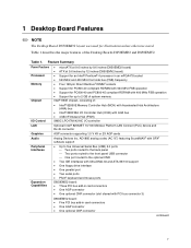
...panel USB connector One port routed to 2 GB of system memory Intel® 850E chipset, consisting of the Desktop Boards D850EMD2 and D850EMV2. 1 Desktop Board Features ✏ NOTE The Desktop Board D850EMD2 layout was used for up to the optional CNR • Two ... Support for illustrations unless otherwise noted. Feature Summary Form Factors Processor Memory Chipset • microATX at 9.6 inches by 9.6 inches (D850EMD2 board) • ATX at 9.6 inches by 12 inches (D850EMV2 board) • Support for an Intel® Pentium® 4 processor in an mPGA478 socket •...
...panel USB connector One port routed to 2 GB of system memory Intel® 850E chipset, consisting of the Desktop Boards D850EMD2 and D850EMV2. 1 Desktop Board Features ✏ NOTE The Desktop Board D850EMD2 layout was used for up to the optional CNR • Two ... Support for illustrations unless otherwise noted. Feature Summary Form Factors Processor Memory Chipset • microATX at 9.6 inches by 9.6 inches (D850EMD2 board) • ATX at 9.6 inches by 12 inches (D850EMV2 board) • Support for an Intel® Pentium® 4 processor in an mPGA478 socket •...
Product Guide
Page 8
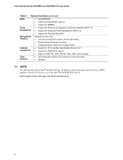
Feature Summary (continued) BIOS • Intel/AMI BIOS • 4 Mbit symmetrical flash memory • Support for SMBIOS Power Management • Support for Advanced Configuration and Power Interface (ACPI 1.0) • Support for Advanced Power ...for the front panel • Speaker ✏ NOTE For information about Intel® desktop boards, including technical product specifications, BIOS updates, and device drivers, go to the Intel World Wide Web site at: http://support.intel.com/support/motherboards/desktop 8 Intel Desktop Boards D850EMD2 and D850EMV2 Product Guide Table 1.
Feature Summary (continued) BIOS • Intel/AMI BIOS • 4 Mbit symmetrical flash memory • Support for SMBIOS Power Management • Support for Advanced Configuration and Power Interface (ACPI 1.0) • Support for Advanced Power ...for the front panel • Speaker ✏ NOTE For information about Intel® desktop boards, including technical product specifications, BIOS updates, and device drivers, go to the Intel World Wide Web site at: http://support.intel.com/support/motherboards/desktop 8 Intel Desktop Boards D850EMD2 and D850EMV2 Product Guide Table 1.

Product Guide
Page 10
...) (tachometer input) Y SCSI hard drive activity LED connector J Intel 82850E Memory Controller Hub (MCH) Z Intel 82801BA I/O Controller Hub (ICH2) K Processor socket AA NEC D720100AGM... USB 2.0 controller L RIMM sockets BB PCI bus add-in card connectors M RIMM fan connector (fan 1) CC Communication and Networking Riser (CNR) (optional) N Power connector DD Chassis fan connector (fan 3) O Floppy drive connector P Primary IDE connector Figure 2. Intel Desktop Boards D850EMD2...
...) (tachometer input) Y SCSI hard drive activity LED connector J Intel 82850E Memory Controller Hub (MCH) Z Intel 82801BA I/O Controller Hub (ICH2) K Processor socket AA NEC D720100AGM... USB 2.0 controller L RIMM sockets BB PCI bus add-in card connectors M RIMM fan connector (fan 1) CC Communication and Networking Riser (CNR) (optional) N Power connector DD Chassis fan connector (fan 3) O Floppy drive connector P Primary IDE connector Figure 2. Intel Desktop Boards D850EMD2...

Product Guide
Page 12
Intel Desktop Boards D850EMD2 and D850EMV2 Product Guide Main Memory The desktop boards have four 2.5 V memory module sockets that support these memory requirements, refer to 2 GB (maximum) onboard capacity utilizing 128/144 Mbit or 256/288 Mbit technology • Single- Intel® 850E Chipset The Intel 850E chipset consists of the following memory features: • Maximum of RDRAM memory •...
Intel Desktop Boards D850EMD2 and D850EMV2 Product Guide Main Memory The desktop boards have four 2.5 V memory module sockets that support these memory requirements, refer to 2 GB (maximum) onboard capacity utilizing 128/144 Mbit or 256/288 Mbit technology • Single- Intel® 850E Chipset The Intel 850E chipset consists of the following memory features: • Maximum of RDRAM memory •...
Product Guide
Page 16
... supervisor password and a user password can be accessed and who can enter either the supervisor password or the user password to /from host memory • A single RJ-45 connector with the following items are set, you must enter either password to view and change all Setup ...Setup. • If both passwords are then available for booting the computer, with connection and activity status LEDs • Jumperless configuration; Intel Desktop Boards D850EMD2 and D850EMV2 Product Guide IDE Auto Configuration If you install an IDE device (such as a hard drive) in your computer. If ...
... supervisor password and a user password can be accessed and who can enter either the supervisor password or the user password to /from host memory • A single RJ-45 connector with the following items are set, you must enter either password to view and change all Setup ...Setup. • If both passwords are then available for booting the computer, with connection and activity status LEDs • Jumperless configuration; Intel Desktop Boards D850EMD2 and D850EMV2 Product Guide IDE Auto Configuration If you install an IDE device (such as a hard drive) in your computer. If ...

Product Guide
Page 18
... the ACPI S3 (Suspend-to support the standard Instantly Available (ACPI S3 sleep state) configuration as PCI 2.2. This includes the memory modules and PCI bus connectors even when the computer appears to be off . While in Table 4. Location of the Standby Power... Indicator Power supplies used with these desktop boards must be capable of providing adequate +5 V standby current. Intel Desktop Boards D850EMD2 and D850EMV2 Product Guide Instantly Available Technology CAUTION For Instantly Available technology, the 5 V standby line for the power supply must be...
... the ACPI S3 (Suspend-to support the standard Instantly Available (ACPI S3 sleep state) configuration as PCI 2.2. This includes the memory modules and PCI bus connectors even when the computer appears to be off . While in Table 4. Location of the Standby Power... Indicator Power supplies used with these desktop boards must be capable of providing adequate +5 V standby current. Intel Desktop Boards D850EMD2 and D850EMV2 Product Guide Instantly Available Technology CAUTION For Instantly Available technology, the 5 V standby line for the power supply must be...
Product Guide
Page 21
... chapter tells you how to: • Install the I/O shield • Install and remove the desktop board • Install and remove a processor • Install and remove memory • Install and remove an AGP card • Connect the IDE cable • Set the BIOS jumper • Clear passwords • Replace the battery Before...
... chapter tells you how to: • Install the I/O shield • Install and remove the desktop board • Install and remove a processor • Install and remove memory • Install and remove an AGP card • Connect the IDE cable • Set the BIOS jumper • Clear passwords • Replace the battery Before...
Product Guide
Page 25
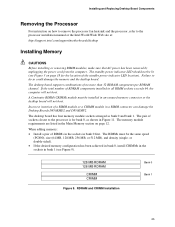
... total number of a RIMM module or a CRIMM module in a RIMM connector can damage the Desktop Boards D850EMD2 and D850EMV2. The pair of the standby power indicator LED location). The memory module requirements are listed in bank 1 (see Figure 3 on page 18 for the location of sockets closest... or the desktop board will not boot. Failure to the processor installation manual or the Intel World Wide Web site at: http://support.intel.com/support/motherboards/desktop Installing Memory CAUTIONS Before installing or removing RIMM modules, make sure that AC power has been removed by unplugging...
... total number of a RIMM module or a CRIMM module in a RIMM connector can damage the Desktop Boards D850EMD2 and D850EMV2. The pair of the standby power indicator LED location). The memory module requirements are listed in bank 1 (see Figure 3 on page 18 for the location of sockets closest... or the desktop board will not boot. Failure to the processor installation manual or the Intel World Wide Web site at: http://support.intel.com/support/motherboards/desktop Installing Memory CAUTIONS Before installing or removing RIMM modules, make sure that AC power has been removed by unplugging...
Product Guide
Page 26
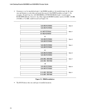
... 128 MB RIMMs of PC800 RDRAM, bank 1 would require PC800 RDRAM also, however, any other and match the speed of installed memory. Intel Desktop Boards D850EMD2 and D850EMV2 Product Guide • If memory is to be installed in bank 1, the RIMM modules to be installed must be the same size and density to each...
... 128 MB RIMMs of PC800 RDRAM, bank 1 would require PC800 RDRAM also, however, any other and match the speed of installed memory. Intel Desktop Boards D850EMD2 and D850EMV2 Product Guide • If memory is to be installed in bank 1, the RIMM modules to be installed must be the same size and density to each...

Product Guide
Page 27
...1 Figure 11. When the module is seated, push down on page 21. 2. Turn off all peripheral devices connected to reach the memory module sockets. 27 The memory pops out of the socket are firmly in "Before You Begin" on page 21. 2. Position the module above the socket. Align the... two small notches in the bottom edge of the socket. Installing a Memory Module OM13624 Removing Memory To remove a memory module, follow these steps: 1. Make sure the clips at each end of the module with the keys in an antistatic package. ...
...1 Figure 11. When the module is seated, push down on page 21. 2. Turn off all peripheral devices connected to reach the memory module sockets. 27 The memory pops out of the socket are firmly in "Before You Begin" on page 21. 2. Position the module above the socket. Align the... two small notches in the bottom edge of the socket. Installing a Memory Module OM13624 Removing Memory To remove a memory module, follow these steps: 1. Make sure the clips at each end of the module with the keys in an antistatic package. ...
Product Guide
Page 32
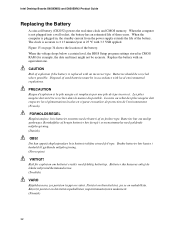
Intel Desktop Boards D850EMD2 and D850EMV2 Product Guide Replacing the Battery A coin-cell battery (CR2032) powers the real-time clock and CMOS memory. When the computer is plugged in, the standby current from the power supply extends the life of three years. When the voltage drops below a certain ...
Intel Desktop Boards D850EMD2 and D850EMV2 Product Guide Replacing the Battery A coin-cell battery (CR2032) powers the real-time clock and CMOS memory. When the computer is plugged in, the standby current from the power supply extends the life of three years. When the voltage drops below a certain ...

Product Guide
Page 35
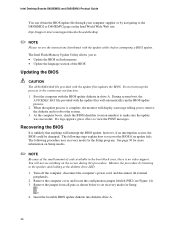
...BIOS for multiple identical systems.) 4. Go to the D850EMV2 or D850EMD2 page and click the Express BIOS Update utility file for creating a bootable flash memory update floppy that combines the functionality of the Intel Flash Memory Update Utility and the ease-of use of the BIOS by ...simple method for the Desktop Boards D850EMV2 or D850EMD2 BIOS. 3. Close all the files you need to update the BIOS. Your system will automatically update your BIOS. Updating the BIOS with the Intel® Flash Memory Update Utility With the Intel Flash Memory Update Utility you can update to a ...
...BIOS for multiple identical systems.) 4. Go to the D850EMV2 or D850EMD2 page and click the Express BIOS Update utility file for creating a bootable flash memory update floppy that combines the functionality of the Intel Flash Memory Update Utility and the ease-of use of the BIOS by ...simple method for the Desktop Boards D850EMV2 or D850EMD2 BIOS. 3. Close all the files you need to update the BIOS. Your system will automatically update your BIOS. Updating the BIOS with the Intel® Flash Memory Update Utility With the Intel Flash Memory Update Utility you can update to a ...
Product Guide
Page 36
... the computer, disconnect the computer's power cord, and disconnect all pins as shown below to set recovery mode for the Setup program. The Intel Flash Memory Update Utility allows you to remove the diskette and to reboot the system. 3. During system boot, the AUTOEXEC.BAT file provided with the ...of the small amount of the BIOS Updating the BIOS CAUTION The AUTOEXEC.BAT file provided with the update files updates the BIOS. Intel Desktop Boards D850EMD2 and D850EMV2 Product Guide You can obtain the BIOS update file through your computer supplier or by listening to the speaker and looking ...
... the computer, disconnect the computer's power cord, and disconnect all pins as shown below to set recovery mode for the Setup program. The Intel Flash Memory Update Utility allows you to remove the diskette and to reboot the system. 3. During system boot, the AUTOEXEC.BAT file provided with the ...of the small amount of the BIOS Updating the BIOS CAUTION The AUTOEXEC.BAT file provided with the update files updates the BIOS. Intel Desktop Boards D850EMD2 and D850EMV2 Product Guide You can obtain the BIOS update file through your computer supplier or by listening to the speaker and looking ...

Product Guide
Page 39
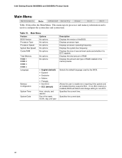
...BIOS identifier MV85010A.86A. Table 6. For the latest BIOS settings, refer to the Intel Desktop Board D850EMD2/D850EMV2 Technical Product Specification or the Intel World Wide Web site: http://support.intel.com/support/motherboards/desktop ✏ NOTE For reference purposes, you make changes to... screens. BIOS Setup Program Menu Bar Maintenance Clears passwords and Boot Integrity Service (BIS)* credentials, and configures extended configuration memory settings Main Allocates resources for the computer. The BIOS Setup program is shown below. 4 Using the Setup Program The ...
...BIOS identifier MV85010A.86A. Table 6. For the latest BIOS settings, refer to the Intel Desktop Board D850EMD2/D850EMV2 Technical Product Specification or the Intel World Wide Web site: http://support.intel.com/support/motherboards/desktop ✏ NOTE For reference purposes, you make changes to... screens. BIOS Setup Program Menu Bar Maintenance Clears passwords and Boot Integrity Service (BIS)* credentials, and configures extended configuration memory settings Main Allocates resources for the computer. The BIOS Setup program is shown below. 4 Using the Setup Program The ...

Product Guide
Page 41
...; USWC • UC (default) User-Defined allows setting memory control and video memory cache mode. This setting identifies the video memory range as "Extended Menu: Used." This submenu becomes available when User Defined is used to memory as required. Selects Uncacheable (UC) video memory cache mode. Memory writes are not performed. Well suited for applications not...
...; USWC • UC (default) User-Defined allows setting memory control and video memory cache mode. This setting identifies the video memory range as "Extended Menu: Used." This submenu becomes available when User Defined is used to memory as required. Selects Uncacheable (UC) video memory cache mode. Memory writes are not performed. Well suited for applications not...
Product Guide
Page 42
.... Specifies the current time. This menu reports processor and memory information and is used by the BIOS. Displays the size of the BIOS. Displays the amount and type of RAM. Specifies the current date. 42 Intel Desktop Boards D850EMD2 and D850EMV2 Product Guide Main Menu Maintenance Main Advanced Security Power Boot Exit Table...
.... Specifies the current time. This menu reports processor and memory information and is used by the BIOS. Displays the size of the BIOS. Displays the amount and type of RAM. Specifies the current date. 42 Intel Desktop Boards D850EMD2 and D850EMV2 Product Guide Main Menu Maintenance Main Advanced Security Power Boot Exit Table...

Product Guide
Page 45
No lets the BIOS configure all devices. Yes clears the PCI/PnP configuration data stored in flash memory on state of the Numlock key. Table 13. Using the Setup Program Boot Configuration Submenu Maintenance Main Advanced Security Power PCI Configuration Boot Configuration ...manual configuration is available for use during lab testing. This option is desired. No does not clear the PCI/PnP configuration data stored in flash memory on the numeric keypad of the Numlock feature on the next boot. Yes lets the operating system configure Plug & Play devices not required to set...
No lets the BIOS configure all devices. Yes clears the PCI/PnP configuration data stored in flash memory on state of the Numlock key. Table 13. Using the Setup Program Boot Configuration Submenu Maintenance Main Advanced Security Power PCI Configuration Boot Configuration ...manual configuration is available for use during lab testing. This option is desired. No does not clear the PCI/PnP configuration data stored in flash memory on the numeric keypad of the Numlock feature on the next boot. Yes lets the operating system configure Plug & Play devices not required to set...


