
Technical Product Specification
Page 5
...13 1.1.3 Board Layout 14 1.1.4 Block Diagram 15 1.2 Online Support ...16 1.3 Operating System Support 16 1.4 Design Specifications 17 1.5 Processor ...20 1.6 System Memory ...21 1.7 Intel® 848P Chipset ...23 1.7.1 Universal 0.8 V / 1.5 V AGP 3.0 Connector 23 1.7.2 USB...24 1.7.3 IDE Support 24 1.7.4 Real-Time Clock, CMOS...Audio Subsystem...28 1.9.1 Audio Subsystem Software 28 1.9.2 Audio Connectors 28 1.9.3 Realtek ALC202A-based Audio Subsystem (Optional 29 1.9.4 Intel® Flex 6 Audio Subsystem (Optional 29 1.10 LAN Subsystem...31 1.10.1 10/100 Mbits/sec LAN Subsystem (Optional...
...13 1.1.3 Board Layout 14 1.1.4 Block Diagram 15 1.2 Online Support ...16 1.3 Operating System Support 16 1.4 Design Specifications 17 1.5 Processor ...20 1.6 System Memory ...21 1.7 Intel® 848P Chipset ...23 1.7.1 Universal 0.8 V / 1.5 V AGP 3.0 Connector 23 1.7.2 USB...24 1.7.3 IDE Support 24 1.7.4 Real-Time Clock, CMOS...Audio Subsystem...28 1.9.1 Audio Subsystem Software 28 1.9.2 Audio Connectors 28 1.9.3 Realtek ALC202A-based Audio Subsystem (Optional 29 1.9.4 Intel® Flex 6 Audio Subsystem (Optional 29 1.10 LAN Subsystem...31 1.10.1 10/100 Mbits/sec LAN Subsystem (Optional...
Technical Product Specification
Page 6
Intel Desktop Board D848PMB Technical Product Specification 2 Technical Reference 2.1 Introduction...43 2.2 Memory Map ...44 2.3 DMA Channels ...44 2.4 Fixed I/O Map...45 2.5 PCI Configuration Space Map 46 2.6 Interrupts ...47 2.7 PCI Interrupt Routing ... 74 2.15.4 Product Ecology Statements 75 2.15.5 Product Certification Markings (Board Level 75 3 Overview of BIOS Features 3.1 Introduction...77 3.2 BIOS Flash Memory Organization 77 3.3 Resource Configuration 78 3.3.1 PCI Autoconfiguration 78 3.3.2 PCI IDE Support 78 3.4 System Management BIOS (SMBIOS 79 3.5 Legacy USB Support 79 ...
Intel Desktop Board D848PMB Technical Product Specification 2 Technical Reference 2.1 Introduction...43 2.2 Memory Map ...44 2.3 DMA Channels ...44 2.4 Fixed I/O Map...45 2.5 PCI Configuration Space Map 46 2.6 Interrupts ...47 2.7 PCI Interrupt Routing ... 74 2.15.4 Product Ecology Statements 75 2.15.5 Product Certification Markings (Board Level 75 3 Overview of BIOS Features 3.1 Introduction...77 3.2 BIOS Flash Memory Organization 77 3.3 Resource Configuration 78 3.3.1 PCI Autoconfiguration 78 3.3.2 PCI IDE Support 78 3.4 System Management BIOS (SMBIOS 79 3.5 Legacy USB Support 79 ...
Technical Product Specification
Page 8
... 5. Back Panel Connectors 51 11. External I /O Shield Dimensions 67 20. ATAPI CD-ROM Connector 54 21. Audio Connectors ...53 12. Desktop Board D848PMB Dimensions 66 19. Supported Memory Configurations 22 6. Front Panel Audio Connector 54 20. Rear Chassis Fan Connector 55 viii Flex 6 Audio Subsystem Block Diagram 30 6. Power and Hardware... Diagram for Front Panel USB Connectors 63 17. Connection Diagram for Front Panel Connector 61 16. Power States and Targeted System Power 36 10. Intel Desktop Board D848PMB Technical Product Specification Figures 1.
... 5. Back Panel Connectors 51 11. External I /O Shield Dimensions 67 20. ATAPI CD-ROM Connector 54 21. Audio Connectors ...53 12. Desktop Board D848PMB Dimensions 66 19. Supported Memory Configurations 22 6. Front Panel Audio Connector 54 20. Rear Chassis Fan Connector 55 viii Flex 6 Audio Subsystem Block Diagram 30 6. Power and Hardware... Diagram for Front Panel USB Connectors 63 17. Connection Diagram for Front Panel Connector 61 16. Power States and Targeted System Power 36 10. Intel Desktop Board D848PMB Technical Product Specification Figures 1.

Technical Product Specification
Page 11
1 Product Description What This Chapter Contains 1.1 Overview ...12 1.2 Online Support ...16 1.3 Operating System Support 16 1.4 Design Specifications 17 1.5 Processor ...20 1.6 System Memory ...21 1.7 Intel® 848P Chipset ...23 1.8 I/O Controller ...26 1.9 Audio Subsystem...28 1.10 LAN Subsystem...31 1.11 Hardware Management Subsystem 33 1.12 Power Management 35 11
1 Product Description What This Chapter Contains 1.1 Overview ...12 1.2 Online Support ...16 1.3 Operating System Support 16 1.4 Design Specifications 17 1.5 Processor ...20 1.6 System Memory ...21 1.7 Intel® 848P Chipset ...23 1.8 I/O Controller ...26 1.9 Audio Subsystem...28 1.10 LAN Subsystem...31 1.11 Hardware Management Subsystem 33 1.12 Power Management 35 11
Technical Product Specification
Page 12
... Local Bus Specification Revision 2.2 • Suspend to 2 GB of system memory Intel® 848P Chipset, consisting of the Intel® Desktop Board D848PMB. Table 1. Intel Desktop Board D848PMB Technical Product Specification 1.1 Overview 1.1.1 Feature Summary Table 1 summarizes the major features of : • Intel® 82848P Memory Controller Hub (MCH) • Intel® 82801EB I/O Controller Hub (ICH5) • 4 Mbit Firmware Hub...
... Local Bus Specification Revision 2.2 • Suspend to 2 GB of system memory Intel® 848P Chipset, consisting of the Intel® Desktop Board D848PMB. Table 1. Intel Desktop Board D848PMB Technical Product Specification 1.1 Overview 1.1.1 Feature Summary Table 1 summarizes the major features of : • Intel® 82848P Memory Controller Hub (MCH) • Intel® 82801EB I/O Controller Hub (ICH5) • 4 Mbit Firmware Hub...
Technical Product Specification
Page 15
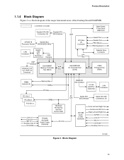
... Board D848PMB. = connector or socket Parallel ATA IDE Connectors (2) Parallel ATA IDE Interface mPGA478 System Bus Processor Socket (400/533/800 MHz) LAN Connector Gigabit LAN PLC (Optional) CSA Interface AGP Interface Universal 0.8/ 1.5 V AGP 3.0 Connector Intel 82848P Memory Controller ...Hub (MCH) AHA Bus USB LPC Bus I/O Controller LPC Bus Intel 82801EB I/O Controller Hub (ICH5) Back Panel/ Front Panel USB Ports Serial Port Parallel Port...
... Board D848PMB. = connector or socket Parallel ATA IDE Connectors (2) Parallel ATA IDE Interface mPGA478 System Bus Processor Socket (400/533/800 MHz) LAN Connector Gigabit LAN PLC (Optional) CSA Interface AGP Interface Universal 0.8/ 1.5 V AGP 3.0 Connector Intel 82848P Memory Controller ...Hub (MCH) AHA Bus USB LPC Bus I/O Controller LPC Bus Intel 82801EB I/O Controller Hub (ICH5) Back Panel/ Front Panel USB Ports Serial Port Parallel Port...
Technical Product Specification
Page 17
....jedec.org/ http://www.jedec.org/ http://developer.intel.com/tec hnology/memory/index.htm continued 17 ftp://download.intel.com/labs/ media/audio/download/ac97r 22.pdf http://www.acpi.info/spec10b. Product Description 1.4 Design Specifications Table 3 lists the specifications applicable to the Desktop Board D848PMB. Table 3. Specifications Reference Name AC '97 ACPI...
....jedec.org/ http://www.jedec.org/ http://developer.intel.com/tec hnology/memory/index.htm continued 17 ftp://download.intel.com/labs/ media/audio/download/ac97r 22.pdf http://www.acpi.info/spec10b. Product Description 1.4 Design Specifications Table 3 lists the specifications applicable to the Desktop Board D848PMB. Table 3. Specifications Reference Name AC '97 ACPI...
Technical Product Specification
Page 20
...supplies have an additional power lead that provides required supplemental power for the most up-to Section 2.8.2.3, page 55 20 Intel Desktop Board D848PMB Technical Product Specification 1.5 Processor ✏ NOTE Refer to Table 4 on the desktop board, otherwise the board will not boot.... • Refer to Thermal Considerations (Section 2.12, page 69) for the D848PMB board Refer to the corresponding connectors on page 21 for a list of supported system bus frequency and memory speed combinations. For information about Power supply connectors Refer to -date list of unsupported...
...supplies have an additional power lead that provides required supplemental power for the most up-to Section 2.8.2.3, page 55 20 Intel Desktop Board D848PMB Technical Product Specification 1.5 Processor ✏ NOTE Refer to Table 4 on the desktop board, otherwise the board will not boot.... • Refer to Thermal Considerations (Section 2.12, page 69) for the D848PMB board Refer to the corresponding connectors on page 21 for a list of supported system bus frequency and memory speed combinations. For information about Power supply connectors Refer to -date list of unsupported...
Technical Product Specification
Page 21
..., but performance and reliability may be ... If non-SPD memory is clocked at 320 MHz. Supported System Bus Frequency and Memory Speed Combinations To use this type of DIMM... Product Description 1.6 System Memory The Desktop Board D848PMB has two DIMM sockets and supports the following memory features: • 2.6 V (only) 184-pin DDR SDRAM DIMMs with...
..., but performance and reliability may be ... If non-SPD memory is clocked at 320 MHz. Supported System Bus Frequency and Memory Speed Combinations To use this type of DIMM... Product Description 1.6 System Memory The Desktop Board D848PMB has two DIMM sockets and supports the following memory features: • 2.6 V (only) 184-pin DDR SDRAM DIMMs with...
Technical Product Specification
Page 22
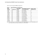
Intel Desktop Board D848PMB Technical Product Specification Table 5 lists the supported DIMM configurations. Supported Memory Configurations DIMM Capacity DDR SDRAM Configuration Density DDR SDRAM Organization Number of DDR Front-side/Back-side SDRAM Devices 64 MB SS 64 Mbit 8 M x 8/empty 8 ... 512 MB SS 512 Mbit 64 M x 8/empty 8 1024 MB DS 512 Mbit 64 M x 8/64 M x 8 16 Note: In the second column, "DS" refers to double-sided memory modules (containing two rows of DDR SDRAM) and "SS" refers to single-sided...
Intel Desktop Board D848PMB Technical Product Specification Table 5 lists the supported DIMM configurations. Supported Memory Configurations DIMM Capacity DDR SDRAM Configuration Density DDR SDRAM Organization Number of DDR Front-side/Back-side SDRAM Devices 64 MB SS 64 Mbit 8 M x 8/empty 8 ... 512 MB SS 512 Mbit 64 M x 8/empty 8 1024 MB DS 512 Mbit 64 M x 8/64 M x 8 16 Note: In the second column, "DS" refers to double-sided memory modules (containing two rows of DDR SDRAM) and "SS" refers to single-sided...
Technical Product Specification
Page 23
... the DIMM sockets prior to installing the AGP video card to http://developer.intel.com/ Chapter 2 1.7.1 Universal 0.8 V / 1.5 V AGP 3.0 Connector The AGP connector supports the following devices: • Intel 82848P Memory Controller Hub (MCH) with Accelerated Hub Architecture (AHA) bus • Intel 82801EB I/O Controller Hub (ICH5) with AHA bus • Firmware Hub (FWH) The GMCH...
... the DIMM sockets prior to installing the AGP video card to http://developer.intel.com/ Chapter 2 1.7.1 Universal 0.8 V / 1.5 V AGP 3.0 Connector The AGP connector supports the following devices: • Intel 82848P Memory Controller Hub (MCH) with Accelerated Hub Architecture (AHA) bus • Intel 82801EB I/O Controller Hub (ICH5) with AHA bus • Firmware Hub (FWH) The GMCH...
Technical Product Specification
Page 26
... 29, page 59 1.7.4 Real-Time Clock, CMOS SRAM, and Battery A coin-cell battery (CR2032) powers the real-time clock and CMOS memory. When the computer is plugged in hard drive controller. For proper operation, this connector should be loaded into a wall socket, the battery has... as the onboard IDE controller. The LED indicates when data is being read from the power supply extends the life of three years. Intel Desktop Board D848PMB Technical Product Specification 1.7.3.3 SCSI Hard Drive Activity LED Connector (Optional) The SCSI hard drive activity LED connector is a 1 x 2-pin...
... 29, page 59 1.7.4 Real-Time Clock, CMOS SRAM, and Battery A coin-cell battery (CR2032) powers the real-time clock and CMOS memory. When the computer is plugged in hard drive controller. For proper operation, this connector should be loaded into a wall socket, the battery has... as the onboard IDE controller. The LED indicates when data is being read from the power supply extends the life of three years. Intel Desktop Board D848PMB Technical Product Specification 1.7.3.3 SCSI Hard Drive Activity LED Connector (Optional) The SCSI hard drive activity LED connector is a 1 x 2-pin...
Technical Product Specification
Page 43
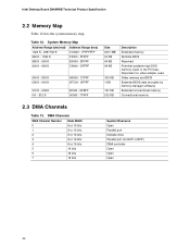
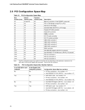
Table 12 describes the system memory map, Table 13 lists the DMA channels, Table 14 shows the I /O Map...45 2.5 PCI Configuration Space Map 46 2.6 Interrupts ...47 2.7 PCI Interrupt Routing Map 48 2.8 .... The remaining sections in this chapter are introduced by text found with their respective section headings. 43 2 Technical Reference What This Chapter Contains 2.1 Introduction...43 2.2 Memory Map ...44 2.3 DMA Channels ...44 2.4 Fixed I /O map, Table 15 defines the PCI configuration space map, and Table 17 describes the interrupts.
Table 12 describes the system memory map, Table 13 lists the DMA channels, Table 14 shows the I /O Map...45 2.5 PCI Configuration Space Map 46 2.6 Interrupts ...47 2.7 PCI Interrupt Routing Map 48 2.8 .... The remaining sections in this chapter are introduced by text found with their respective section headings. 43 2 Technical Reference What This Chapter Contains 2.1 Introduction...43 2.2 Memory Map ...44 2.3 DMA Channels ...44 2.4 Fixed I /O map, Table 15 defines the PCI configuration space map, and Table 17 describes the interrupts.
Technical Product Specification
Page 44
... - 7FFFF Size 2047 MB 64 KB 64 KB 96 KB 160 KB 1 KB 127 KB 512 KB Description Extended memory Runtime BIOS Reserved Potential available high DOS memory (open to the PCI bus). DMA Channels DMA Channel Number 0 1 2 3 4 5 6 7 Data Width .... Video memory and BIOS Extended BIOS data (movable by memory manager software) Extended conventional memory Conventional memory 2.3 DMA Channels Table 13. Table 12. DFFFF 640 K - 800 K 639 K - 640 K 512 K - 639 K 0 K - 512 K A0000 - Intel Desktop Board D848PMB Technical Product Specification 2.2 Memory Map Table 12 lists the system memory map. FFFFF...
... - 7FFFF Size 2047 MB 64 KB 64 KB 96 KB 160 KB 1 KB 127 KB 512 KB Description Extended memory Runtime BIOS Reserved Potential available high DOS memory (open to the PCI bus). DMA Channels DMA Channel Number 0 1 2 3 4 5 6 7 Data Width .... Video memory and BIOS Extended BIOS data (movable by memory manager software) Extended conventional memory Conventional memory 2.3 DMA Channels Table 13. Table 12. DFFFF 640 K - 800 K 639 K - 640 K 512 K - 639 K 0 K - 512 K A0000 - Intel Desktop Board D848PMB Technical Product Specification 2.2 Memory Map Table 12 lists the system memory map. FFFFF...
Technical Product Specification
Page 46
... Yes Yes Configuration Space Map bus numbers • PCI bus connectors − bus number = 01 • Intel 82562EZ 10/100 LAN PLC − bus number = 01 • AGP add-in card − bus ... PCI bus connectors − bus number = 02 • AGP add-in card installed? Intel Desktop Board D848PMB Technical Product Specification 2.5 PCI Configuration Space Map Table 15. PCI Configuration Space Map Bus Number (...00 00 00 00 00 Description Memory controller of Intel 82848P component PCI to CSA Bridge (virtual PCI-to-PCI) Hub link to PCI bridge Intel 82801EB ICH5 PCI to LPC bridge...
... Yes Yes Configuration Space Map bus numbers • PCI bus connectors − bus number = 01 • Intel 82562EZ 10/100 LAN PLC − bus number = 01 • AGP add-in card − bus ... PCI bus connectors − bus number = 02 • AGP add-in card installed? Intel Desktop Board D848PMB Technical Product Specification 2.5 PCI Configuration Space Map Table 15. PCI Configuration Space Map Bus Number (...00 00 00 00 00 Description Memory controller of Intel 82848P component PCI to CSA Bridge (virtual PCI-to-PCI) Hub link to PCI bridge Intel 82801EB ICH5 PCI to LPC bridge...
Technical Product Specification
Page 68
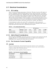
... on the board that impact its power delivery subsystems. The analysis does not include PCI add-in Board Considerations The Desktop Board D848PMB is similar to a heavy gaming environment with no applications running and no USB current draw. Connecting the processor fan to a... fan 0.6 A 68 Use the datasheets for add-in boards for add-in cards, such as PCI, to the processor, memory, and USB ports. Intel Desktop Board D848PMB Technical Product Specification 2.11 Electrical Considerations 2.11.1 DC Loading Table 37 lists the DC loading characteristics of the fan connectors. Table...
... on the board that impact its power delivery subsystems. The analysis does not include PCI add-in Board Considerations The Desktop Board D848PMB is similar to a heavy gaming environment with no applications running and no USB current draw. Connecting the processor fan to a... fan 0.6 A 68 Use the datasheets for add-in boards for add-in cards, such as PCI, to the processor, memory, and USB ports. Intel Desktop Board D848PMB Technical Product Specification 2.11 Electrical Considerations 2.11.1 DC Loading Table 37 lists the DC loading characteristics of the fan connectors. Table...
Technical Product Specification
Page 77
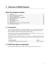
...a revision code. The BIOS displays a message during POST identifying the type of BIOS Features What This Chapter Contains 3.1 Introduction...77 3.2 BIOS Flash Memory Organization 77 3.3 Resource Configuration 78 3.4 System Management BIOS (SMBIOS 79 3.5 Legacy USB Support 79 3.6 BIOS Updates ...80 3.7 Recovering BIOS Data ...the two match. For information about The Desktop Boards' compliance level with Intel® Rapid BIOS Boot 83 3.10 BIOS Security Features 84 3.1 Introduction The Desktop Board D848PMB use an Intel/AMI BIOS that is poweredup, the BIOS compares the CPU version and ...
...a revision code. The BIOS displays a message during POST identifying the type of BIOS Features What This Chapter Contains 3.1 Introduction...77 3.2 BIOS Flash Memory Organization 77 3.3 Resource Configuration 78 3.4 System Management BIOS (SMBIOS 79 3.5 Legacy USB Support 79 3.6 BIOS Updates ...80 3.7 Recovering BIOS Data ...the two match. For information about The Desktop Boards' compliance level with Intel® Rapid BIOS Boot 83 3.10 BIOS Security Features 84 3.1 Introduction The Desktop Board D848PMB use an Intel/AMI BIOS that is poweredup, the BIOS compares the CPU version and ...
Technical Product Specification
Page 79
...; BIOS data, such as the BIOS revision level • Fixed-system data, such as peripherals, serial numbers, and asset tags • Resource data, such as memory size, cache size, and processor speed • Dynamic data, such as event detection and error logging Non-Plug and Play operating systems, such as follows...
...; BIOS data, such as the BIOS revision level • Fixed-system data, such as peripherals, serial numbers, and asset tags • Resource data, such as memory size, cache size, and processor speed • Dynamic data, such as event detection and error logging Non-Plug and Play operating systems, such as follows...
Technical Product Specification
Page 80
... to Section 1.2, page 16 3.6.1 Language Support The BIOS Setup program and help messages are available on the Web. • Intel® Flash Memory Update Utility, which enables automated updating while in the Windows environment. The default language is US English, which are supported in ...: US English, German, Italian, French, and Spanish. Other USB devices are not supported in the BIOS Setup program. 80 Intel Desktop Board D848PMB Technical Product Specification To install an operating system that supports USB, verify that the updated BIOS matches the target system to prevent...
... to Section 1.2, page 16 3.6.1 Language Support The BIOS Setup program and help messages are available on the Web. • Intel® Flash Memory Update Utility, which enables automated updating while in the Windows environment. The default language is US English, which are supported in ...: US English, German, Italian, French, and Spanish. Other USB devices are not supported in the BIOS Setup program. 80 Intel Desktop Board D848PMB Technical Product Specification To install an operating system that supports USB, verify that the updated BIOS matches the target system to prevent...
Technical Product Specification
Page 81
...with a custom splash screen. The custom splash screen can be programmed into the flash memory using the BIOS recovery mode. Information about The Intel World Wide Web site Refer to assist with the Intel branded logo. The BIOS can be lost if a power outage occurs while the ... recovering the BIOS, be a standard 1.44 MB diskette not a 120 MB diskette. BIOS upgrades and the Intel Flash Memory Update Utility are available from an LS-120 diskette (in flash memory. A utility is configured to it will share space with creating a custom splash screen. For example, the data...
...with a custom splash screen. The custom splash screen can be programmed into the flash memory using the BIOS recovery mode. Information about The Intel World Wide Web site Refer to assist with the Intel branded logo. The BIOS can be lost if a power outage occurs while the ... recovering the BIOS, be a standard 1.44 MB diskette not a 120 MB diskette. BIOS upgrades and the Intel Flash Memory Update Utility are available from an LS-120 diskette (in flash memory. A utility is configured to it will share space with creating a custom splash screen. For example, the data...


